The meter will work as follows:
- The meter generates an oscillating signal. Different frequencies can be used in order to account for different capacitance ranges. (1 kHz, 10 kHz, 100 kHz).
- The device under test is subjected to the oscillating signal, which should have a peak to peak voltage of 300 mV or less to avoid triggering semiconductors and most Schottky diodes.
- The current flowing through the capacitor under test is measured with a shunt. The resulting signal will have a peak to peak voltage that is a function of the capacitor impedance at the oscillating frequency plus the esr.
- The phase shift between the signal measured in step 3 and the signal generated in step 1 is measured in order to calculate the capacitance. Alternatively, the sine wave component 90º out of phase with that generated in step 1 can be measured to calculate the capacitance.
- The esr can be measured in a similar way, measuring the component of the sine wave that is in phase with the oscillating signal generated in step 1.

 Jesse
Jesse
 Zach Armstrong
 Ellie T
Hi
I'm making another impedance meter :)
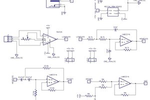
About oscillator - I filter square wave from microcontroller with 3rd order active filter. I do synchronous measurements so probably some harmonics is not an issue for me.
In my design I use auto balancing bridge method (with I-V converter using op-amp). Amplified (with switched gain amplifiers) current and voltage are converted with ADC and then microcontroller computes fundamental frequency real and imaginary parts, using DFT formula.
Inspiring (for me) resources are: Keysight Technologies Impedance Measurement Handbook and service manuals of old impedance meters (like 4192A).