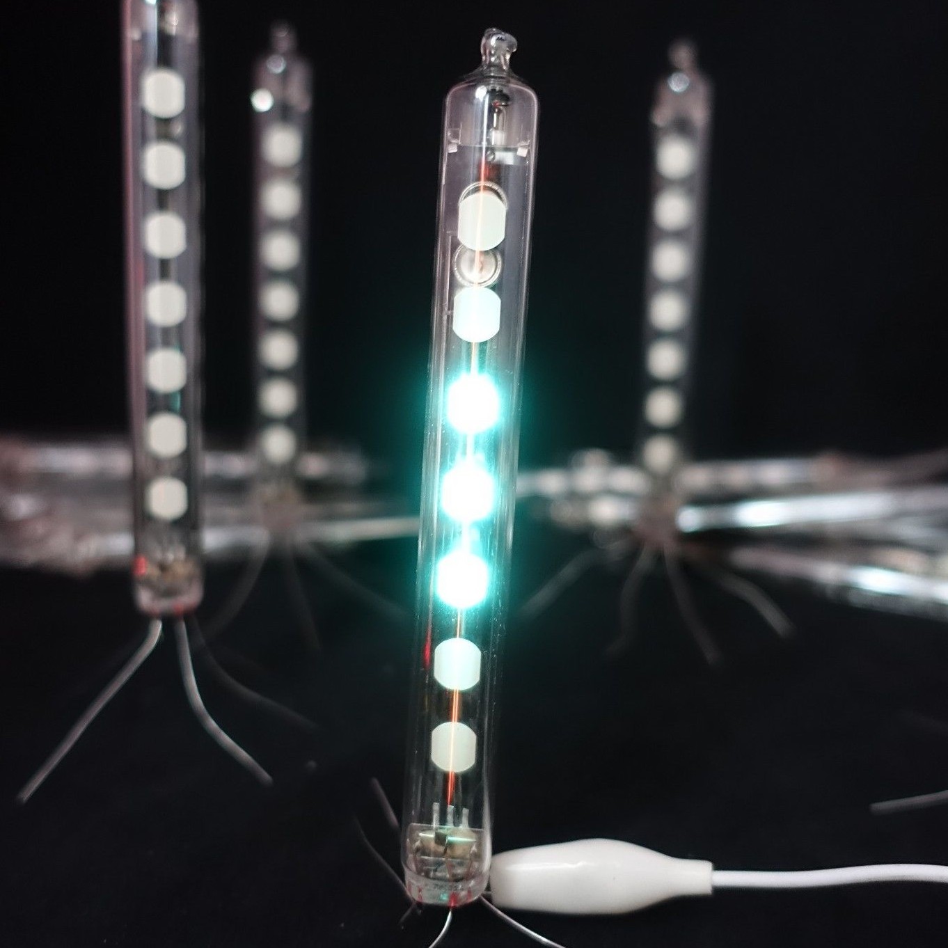
 Mile
MileVFD is indication vacuum tube with three electrodes: Filament, Grid and Anodes. When supplied with voltage grid emits electrons. Depending on the polarity of supplied voltage grid accelerates or deflects those electrons preventing them from reaching anodes. When an anode is supplied with a positive voltage, it will attract the electrons which have been accelerated through the grid. Anodes are coated with phosphor which emits light when hit by the electrons.
For IV-3A tube datasheet values for Filament, Grid and Anode voltages are:
Filament - 0.85 ± 0.15 VAC
Grid - 15-30 V
Anodes - 15-30 V
Generating grid and anode voltages is pretty straight forward by using boost converter or charge pump(depending on the required voltage and power source). Generating filament voltage on the other hand is a little more complicated. It is critical that the filament voltage is supplied within the specified ratings since the lifetime of a VFD affected by the extent of evaporation of oxide materials coated onto the tungsten filament wires.
*Examples of overdriving filament (Notice thin red line).
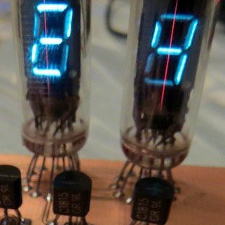 |  |
There are 3 ways to drive filament:
1. AC Filament Drive (50 or 60 Hz) - Most optimal method that uses transformer and mains power. Not applicable in watches :)
2. DC Filament Drive - Worst option. Introduces "luminance slant" - difference in luminance at opposite sides of the display due to the DC voltage drop. Effect is more apparent on larger displays than on single digit tubes.
3. Pulse Filament Drive (High Frequency RMS) - Most optimal method for my application. Use of astable multivibrator circuits for generating bipolar voltage pulses.
For generating filament drive voltage I am using LM4819 IC (mono bridged power amplifier - BTL amplifier). LM4819 consists of two amplifiers, one with unstable feedback loop (oscillator) whose output is feed into inverting input of second amplifier. Load is connected between the outputs of two amplifiers therefore the name for this topology - Bridge tied load. Full schematics of the circuit will be posted when I get some time to organize them because now they look like dogs breakfast.
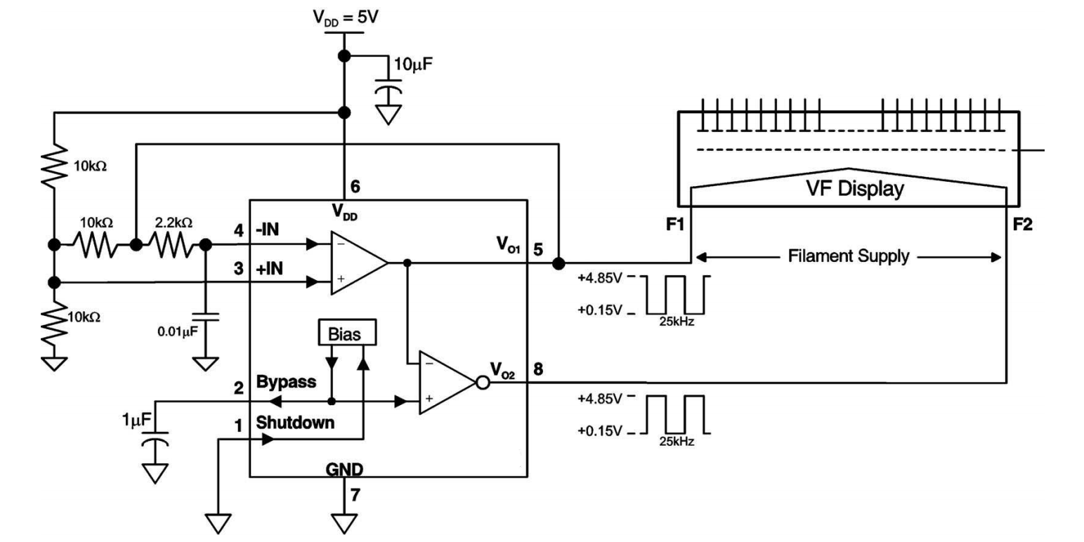
When configuring amplifier 1/2 duty factor should be set, and the peak to peak pulse wave form should be 1.5 times or less than the RMS value. A frequency range of 10 kHz to 200 kHz is recommended.
For the end picture that shows current sate of the watch (Will post full description of progress in future project log. For now there is not much going on just testing of the circuit).
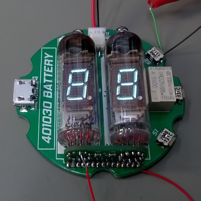
Yes that is small relay :)
Discussions
Become a Hackaday.io Member
Create an account to leave a comment. Already have an account? Log In.