 Carlos Barrera
State of the Art - Novel InFlow Tech - Featured Project Development:
1-Gearturbine, RotaryTurbo, 2-Imploturbocompressor, One Compression Step:
*Wordpress Blog State of the Art Novel InFlow Gearturbine Imploturbocompressor:
http://stateoftheartnovelinflowtech.blogspot.mx/
*1-GEARTURBINE PROJECT, Rotary-Turbo-InFlow Tech, Atypical InFlow Thermodynamic, Technology Proposal Submission, Novel Fueled Motor Engine Type:
*1-GEARTURBINE BEHANCE Images Gallery Portafolio:
https://www.behance.net/gallery/21019191/Novel-Rotary-Turbo-InFlow-Tech-Gearturbine-Project
·State of the art Innovative concept Top system Higher efficient percent.*Power by bar, for Air-Planes, Sea-Boats, Land-Transport & Dynamic Power-Plant Generation.
-Have similar system of the Aeolipile Heron Steam device from Alexandria 10-70 AD. -New Form-Function Motor-Engine Device. Next Step, Epic Design Change, Broken-Seal Revelation. -Desirable Power-Plant Innovation. Next trend wave toward global technological coming change.
-YouTube; * Atypical New • GEARTURBINE / Retrodynamic = DextroRPM VS LevoInFlow + Ying Yang Thrust Way Type - Non Waste Looses
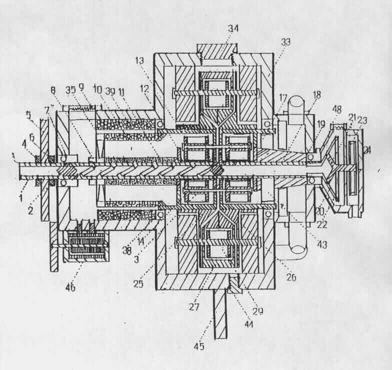
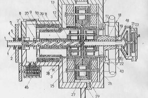
The present invention relates to a compression and pushing motor characterized in that it is composed of a housing, said housing accommodates a rotor rotating in its internal space supported by a pair of gears whose passage coincides with the inner surface of the rotor; A rotor (or core) that internally has flow ducts presented one in reverse of another, balanced these, begin at the point where they end; Has several cavity points for reaction turbines, as well as two combustion chambers isolated by means of a system of nozzles and presented in the manner of poles, that is on opposite sides of one another, but their flow with the same circular direction of the rotor when It rotates; The rotor also has several fluid conduits radially presented; A hollow power transmission rod arranged and traversing in the center of the rotor, which in its interior flows the lubricant and fuel with movement of the ends towards the center, at this point by means of the centrifugal force of the rotor reaches the required parts; In the bar is arranged an air intake fan which by rotating the rotor suction air and introduces it to the internal ducts of the rotor with an initial compression, next to this fan is a current collector that generates the necessary electricity and Together with a coil, activates the current necessary for combustion; A center of the nucleus in which the formation of the internal ducts of the rotor begins and ends (in and out); Said center of the core has arranged a pair of semi-cylindrical cavities housing two pairs of turbochargers said core of the core is diagonally traversed by fluid conduits exiting from the bar to the combustion bed and lubrication points and by the centrifugal force of the rotation Of the rotor sends the fluids to the required points due to their radial direction; Exhaust blades are the point of exit of the exhaust gases that leave the internal ducts of the rotor and contrareaccionan with the fixed blade in the last point of use of propulsion of the motor; Two combustion chambers contained in the rotor's strong ducts when the parts forming it are joined, said chambers have their flame in front of the thrust blade, which is connected by a common shaft to a gear located on the outside of the rotor and Coincides with the internal gear of the housing; A starter motor which by means of a gear engages the starter gear attached to the bar.
-This innovative concept consists of hull and core where are held all 8 Steps of the work-flow which make the concept functional. The core has several gears and turbines which are responsible for these 8 steps (5 of them are dedicated to the turbo stages). The first step is fuel compression, followed by 2 cold turbo levels. The fourth step is where the fuel starts burning – combustion stage,...
Read more »

+PLUS; *State of the Art, Novel Technology, Featured Project Development / Space, Satellite and Habitat, Power-Plant, Generator, Self-Feed Unit; H2O=>HHO=>H2O=>HHO=>Etc... *4 Systems All in One Unit, One By One, Plus Four-4 Projects added One to Other; *·1-Gearturbine, ·2-Imploturbocompressor, ·3-Dynamic Generator, ·4-Electrolysis System:
·1-GEARTURBINE; Rotary-Turbo-InFlow Tech,Have the similar basic system of the Aeolipilie Heron Steam Turbine device from Alexandria 10-70 AD * With Retrodynamic = DextroRPM VS LevoInFlow + Ying Yang Way Power Type - Non Waste Looses *8X/Y Thermodynamic CYCLE Way Steps. 4 Turbos, Higher efficient percent. No blade erosion by sand & very low heat target signature Pat:197187IMPI MX Dic1991 Atypical Motor Engine Type.
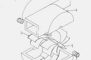
·2-IMPLOTURBOCOMPRESSOR; Implo-Ducted, One Moving Part System Excellence Design - The InFlow Interaction comes from Macro-Flow and goes to Micro-Flow by Implossion - Only One Compression Step; Inflow, Compression and outflow at one simple circular dynamic motion / New Concept. To see a Imploturbocompressor animation, is possible on a simple way, just to check an Hurricane Satellite view, and is the same implo inflow way nature.
·Note-Plus-This-Two Projects / to complete all the System Work:
(Self-Feed Unit Space Power-Plant-H2O=>HHO)
·3-Dynamic Generator/New Kind.
·4-Electrolysis System/BioDesign.
*(3&4-Hide-Cards-on-the-Hand).