 int-smart
Introduction:
This project aims at building a Quadrotor test bed for trying out autonomous algorithms. The quadrotor is a fairly complex machine which can serve as a useful tool to test out new algorithms for your research. I intend to test localization and mapping algorithms on this test bed.
Localization:
For mobile devices, the ability to navigate the environment is crucial. To navigate a complex environment with unknown obstacles, it becomes paramount to know where the robot is located. This need to know where the robot location is a highly complex subject which can be solved through a variety of algorithms. The goal for the robot can only be achieved if the localization system helps the system navigate without crashing into unknown territory.
Hardware used:
Scanse Sweep Lidar: https://www.sparkfun.com/products/14117
Software used:
ROS on beaglebone blue
Point CLoud library
Ardupilot : https://github.com/mirkix/ardupilotblue
Approach:
The aim of this project is to implement certain open source ROS algorithms on the test bed. The test bed itself can be assembled using the components. I intend to work on ICP and particle filters on the Quadrotor. The beaglebone blue would be used to run the Ardupilot on it providing motion commands to the rover. I intend to install ROS indigo on the platform so as to simultaneously work on the Ardupilot and ROS. The scans or the pointcloud data would be generated by the Scanse sweep module which have the necessary ROS drivers https://github.com/scanse/sweep-ros.
Iterative closest point (ICP) is an algorithm employed to minimize the difference between two clouds of points. ICP is often used to reconstruct 2D or 3D surfaces from different scans, to localize robots and achieve optimal path planning.
The experiments that I need to conduct is basically ICP scan matching and registering. I am trying to get the pose of the vehicle using the scan registering process. The pose can help me get the correct position of the vehicle in the unknown environment. To implement the scan matching, I would be using the Point cloud library. Point cloud library is an easy interface for implementing localization algorihtms. ICP implementation from the PCL can help me get the maps necessary for the mapping process.
The position of the copter as derived by the Ardupilot controls can be published on a ROS node. This vealue is then used to filter the value that we get from the scan matching. The updated position can be used as the position of the rotor.
Deliverables:
The project deliverables would be a software and hardware solution integrating Ardupilot and ROS for implementing localization and mapping modules from ROS into Ardupilot.
 Here g and h represent the non-linear model. The other notations are the same as those in Kalman filter equations. After applying the non-linear models to the state x which in our case is a gaussian, we get a distribution that is not a gaussian. We try to approximate this distribution with a gaussian to get the final state. This is done by using Taylor expansion which linearizes the function at the mean.
 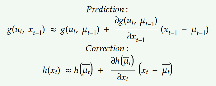 Let the jacobians for motion and observation model be,
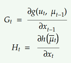 Substituting the above linear model into the Bayes filter equations we get,
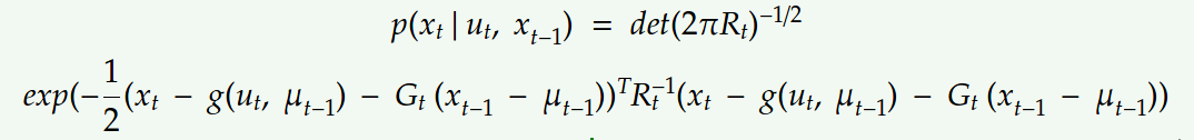
 Replacing the Kalman filter equations with the new linear model we get:
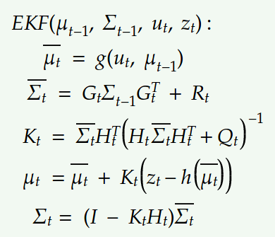 The above equations show the Extended Kalman filter where we just linearized the non-linear modelwith Taylor expansion. This method however performs linearization just at the mean due to which it is not representative of the actual non-linear model. It works well in cases where the non-linearities are moderate.
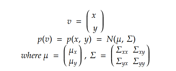
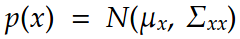 The conditional of x with respect to y is:
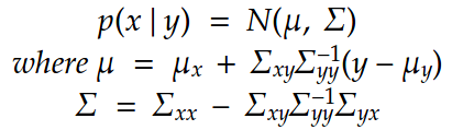 The kalman filter linear and observation models can be thus represented by:
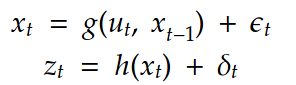
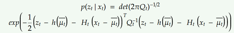
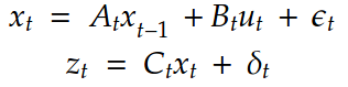 where x represent the motion model and z represent the observation model. Here the motion noise epsilon is zero mean gaussian with covariance R and the observation noise is zero mean with Q covariance.
 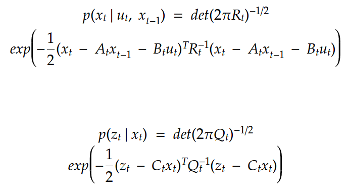 The above values can be substituted in the prediction and correction step below:
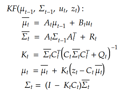 The first two equations show the predictions for the mean and covariance of the state and the last two equations give us the final belief of the state considering the observations. Once again, all of this is just applicable when we have linear motion and observation model. For non-linear models we consider the Extended Kalman filter that I would be explaining in my next post.
 Step 2:

 Gene Foxwell
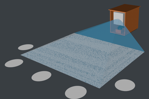
 Timescale
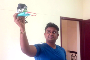
 Anand Uthaman
 Arkadi