 techav
Pieces are starting to come together. I have the circuit around 2/3rds completed. The ESP8266 side of the circuit has been working on-board, since that was the only way I could test it. The AVR is running and responding to serial commands and properly outputting the various clock and control signals. I've wired the AVR to the first TLC5940 and need to test its LED outputs before wiring in the second TLC5940. I've not yet updated the code for driving two TLC5940 chips, so I've added a header to Reset, TxD, and RxD to ease code updates (and testing/debugging). The board is looking pretty full, but I have just enough room to add the four remaining pull-up/down resistors my schematic calls for. I'm anxious to get all the pieces communicating together, but for once I'm trying to really take my time and test as I go. Still though, that green/white pair coming from the ESP8266 (Data and Clock to the AVR) is just begging to be routed to final positions.
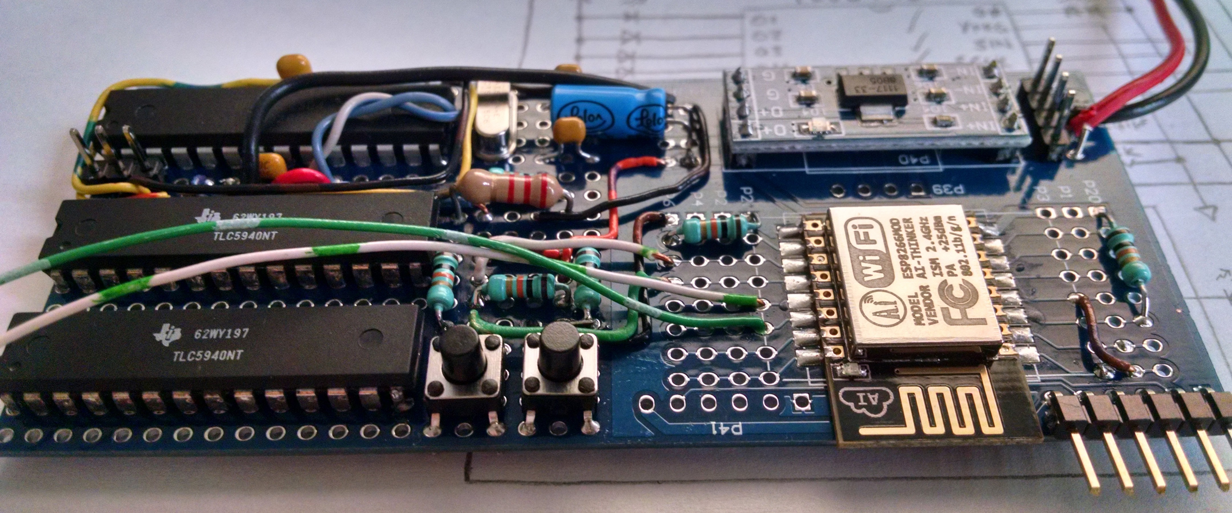
For curiosity's sake, I want to try laying out a board for this in Eagle to see if I can a double-sided board more compact than this.
The display segments, masks, and mounts are coming along as well. I didn't have any foam core board, and I've not been able to bring myself to paying $6 for a full sheet when all I need is a 6x8" piece, so I've changed my mounting plans some. Instead of inserting the LEDs straight-on through foam core, I've cut channels out of left-over matte board to allow each LED to be placed sideways. I think this will help diffuse a little better. ... Which brings me to another silly oversight on my part. I ordered water clear LEDs. This project really needs diffused. So after soldering leads onto the LEDs, I sanded each with 400 grit sandpaper. Worked pretty well and helped diffuse them quite a bit.
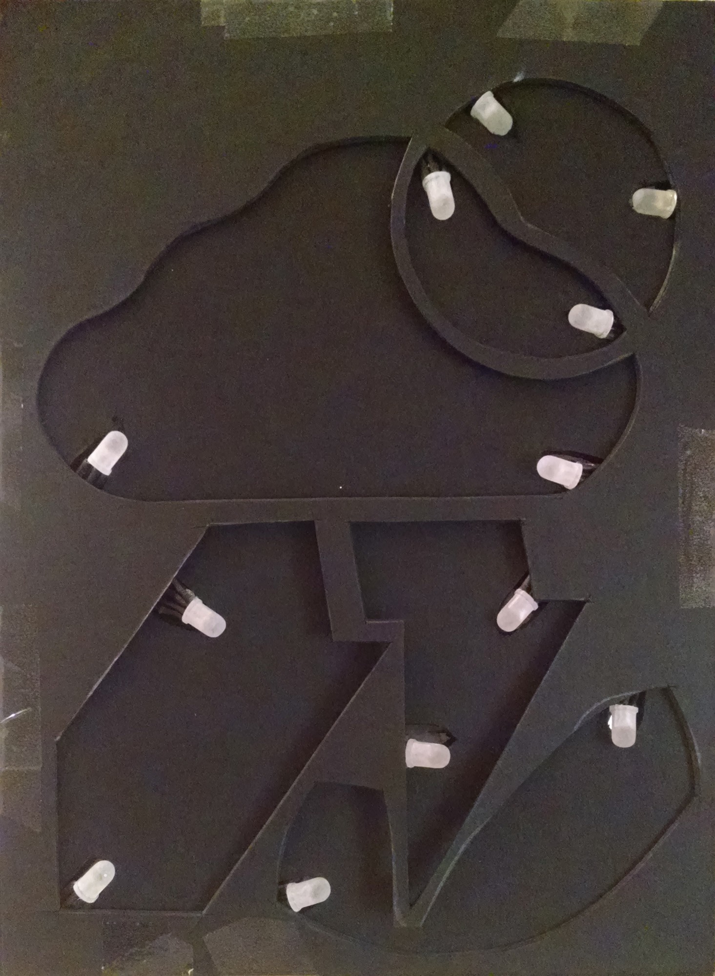
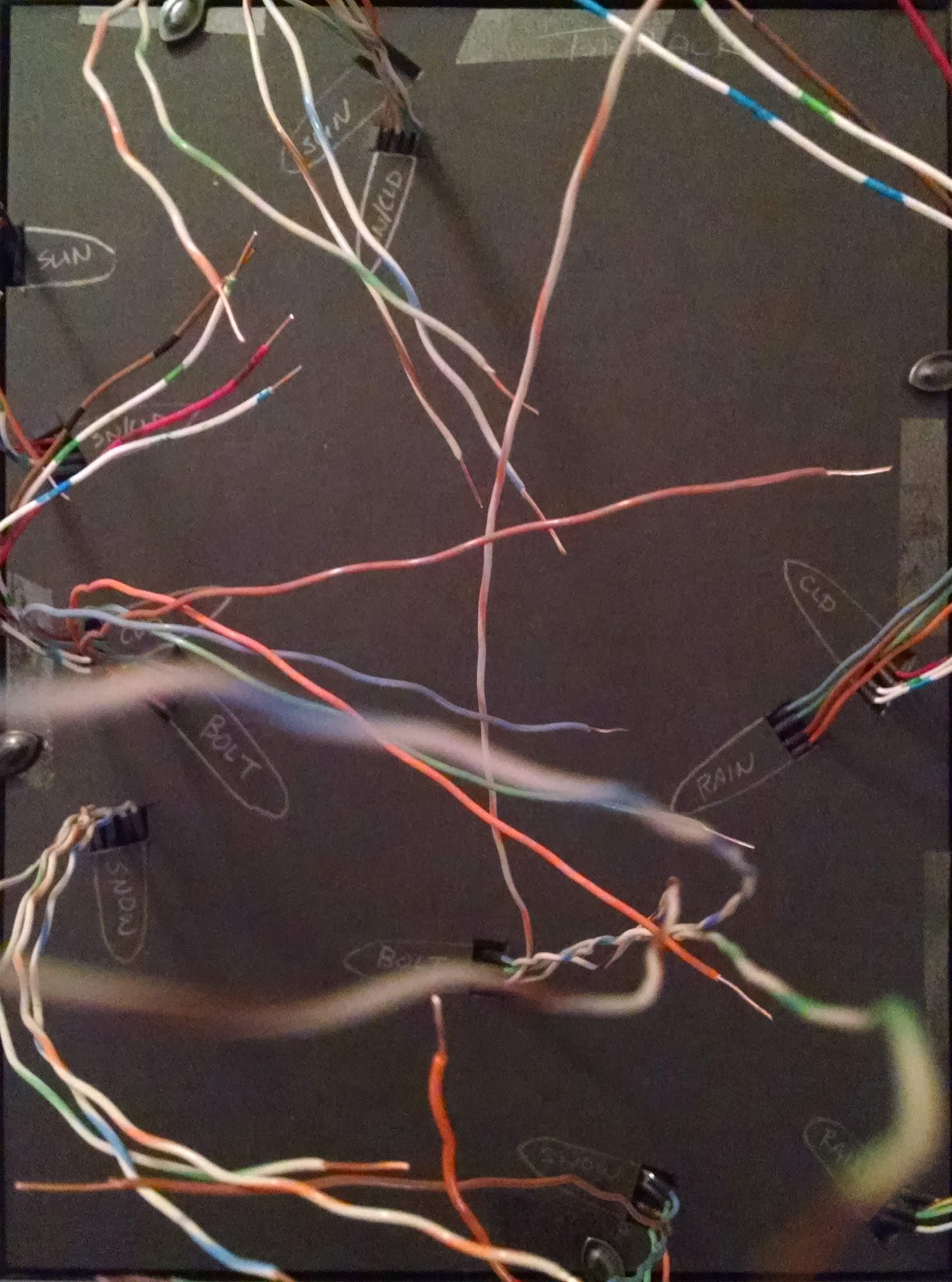 Here we have the front and back of the mask and mount stack with LEDs in place as they are now. It had been my thought to keep everything black in the hopes of finding either dark tinted or mirror tinted glass to keep the segments from being visible unless currently lit. I don't think I'll be able to find anything like that for a price reasonable for this project. So now that I have this stack all assembled, I'm thinking I should put foil or at least white paper behind the section divider mask (seen far left) to reflect rather than absorb stray light from the LEDs for that much better of output. While I have it disassembled, I may cut another section divider mask to give a little more distance between the LEDs and the vellum diffuse screen. Right now a lit LED is basically a hot spot of light instead of an evenly lit segment. I really need more LEDs to pull it off properly, but I'm at the limits of what I can manage on this project (especially as full as my board already is).
Discussions
Become a Hackaday.io Member
Create an account to leave a comment. Already have an account? Log In.