 Nigel
NigelA couple of days ago I was asked the question of "Why not just get all your data over OBD?" and thinking about it I was able to think of a few reasons why I'm happy with my approach.
- Getting a functional prototype will be much easier. Once I have something up and running my progress will accelerate, so this is a good incentive to stick with the way things are.
- Direct sensing will give me a lower latency and potentially higher bandwidth, this will come in handy once I start trying to get as fast of a refresh rate as possible.
- Not every car uses the same OBD standard, and many race cars do not have an OBD compatible ECU at all. Additionally, doing direct sensing will allow MagiLog to be used in non-automotive applications.
All of that said, I'm not discounting OBD altogether, MagiLog will still be capable of it, but direct sensing will be heavily encouraged as the primary data source.
For the simulator side of the project, I'm aiming to create a modular system to allow me to mix and match which functions I can test at once. One of the modules will contain the power management and from there supply all the other modules with 12V and 5V. I ended up sketching a rough idea of what I want it to look like:
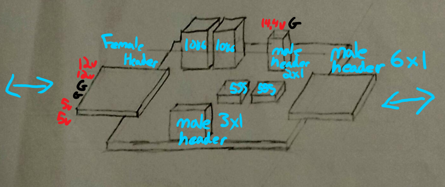
The side headers will allow me to daisy chain modules and all of the outputs will be towards the front of the boards.
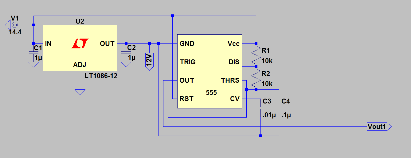
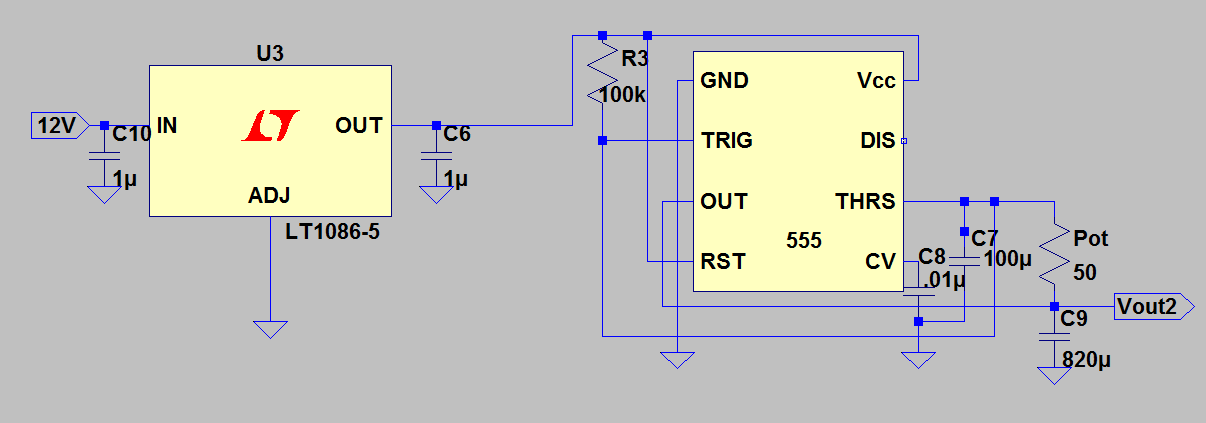
As I mentioned last update, the first module I'm making is the analog input simulator. This module will have 2 outputs, a noise 12-14V output replicating a dirty automotive power rail and a 0-5V oscillating output to represent a sensor output.
Both circuits are based off of 555 timers. For the HV circuit we set VCC to +14.4V and set the 555's ground to the 12V rail, this will allow us to get that high speed oscillation between the voltages we are looking for. I selected the resistors to give me a roughly 66% duty cycle.
For the 5V circuit we leave the discharge pin floating and then power the threshold capacitor with our output. This will give us an exactly 50% duty cycle with the ability to tune the frequency with a potentiometer. I popped a big smoothing
capacitor on the output so that we get some values to read that aren't just 5V and 0V.
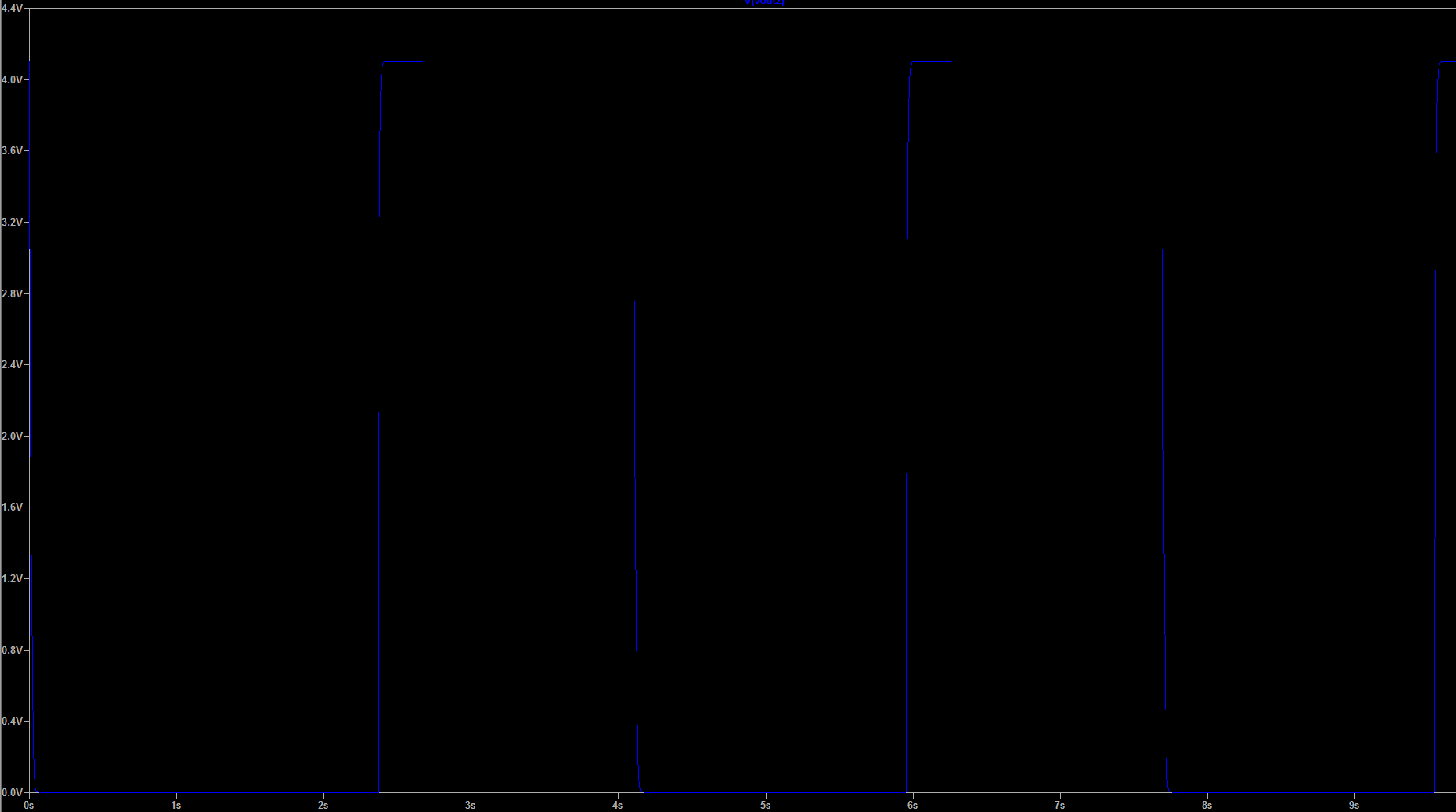
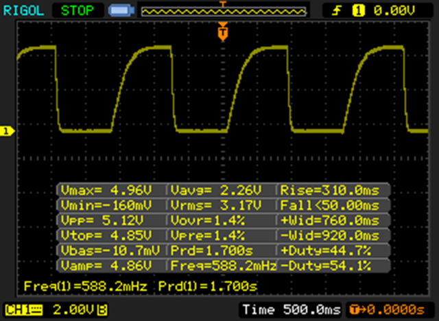
Now that you've seen the circuits, let's go over the outputs starting with the simulated 14V output.
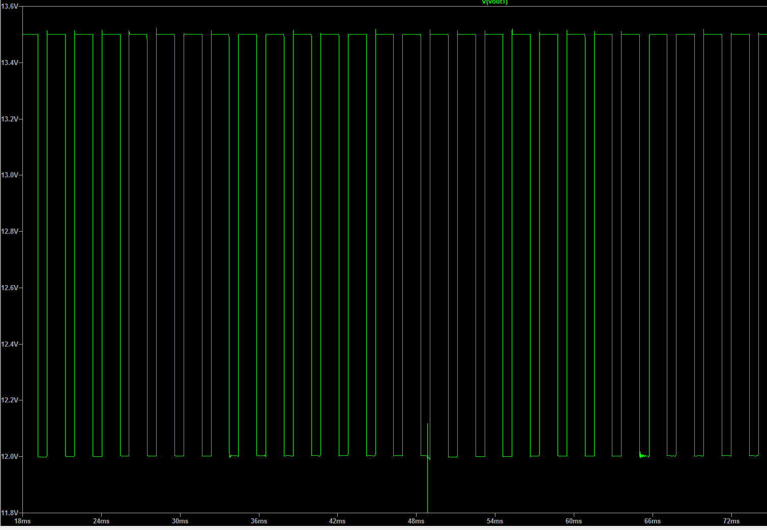
This is pretty much what we want with a frequency of around 500Hz. That said, I'm thinking of increasing the frequency up to somewhere between 2-5KHz and throwing on a smoothing cap to narrow up the voltage range. Though… I should probably just get a scope measurement from someone's car to make sure this output isn't literal trash.
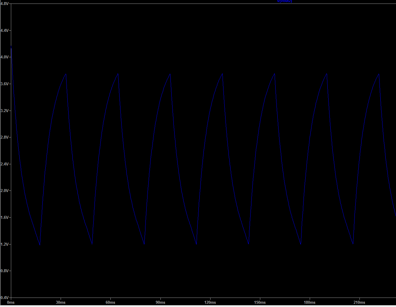
Thankfully I'm more satisfied with the LV oscillator. Here's the graphs simulating inputs at the low and high frequency bounds.
Slow:
Fast:
So finaaaally we to building some actual hardware. As is tradition, we start off with a breadboarded version to test out.
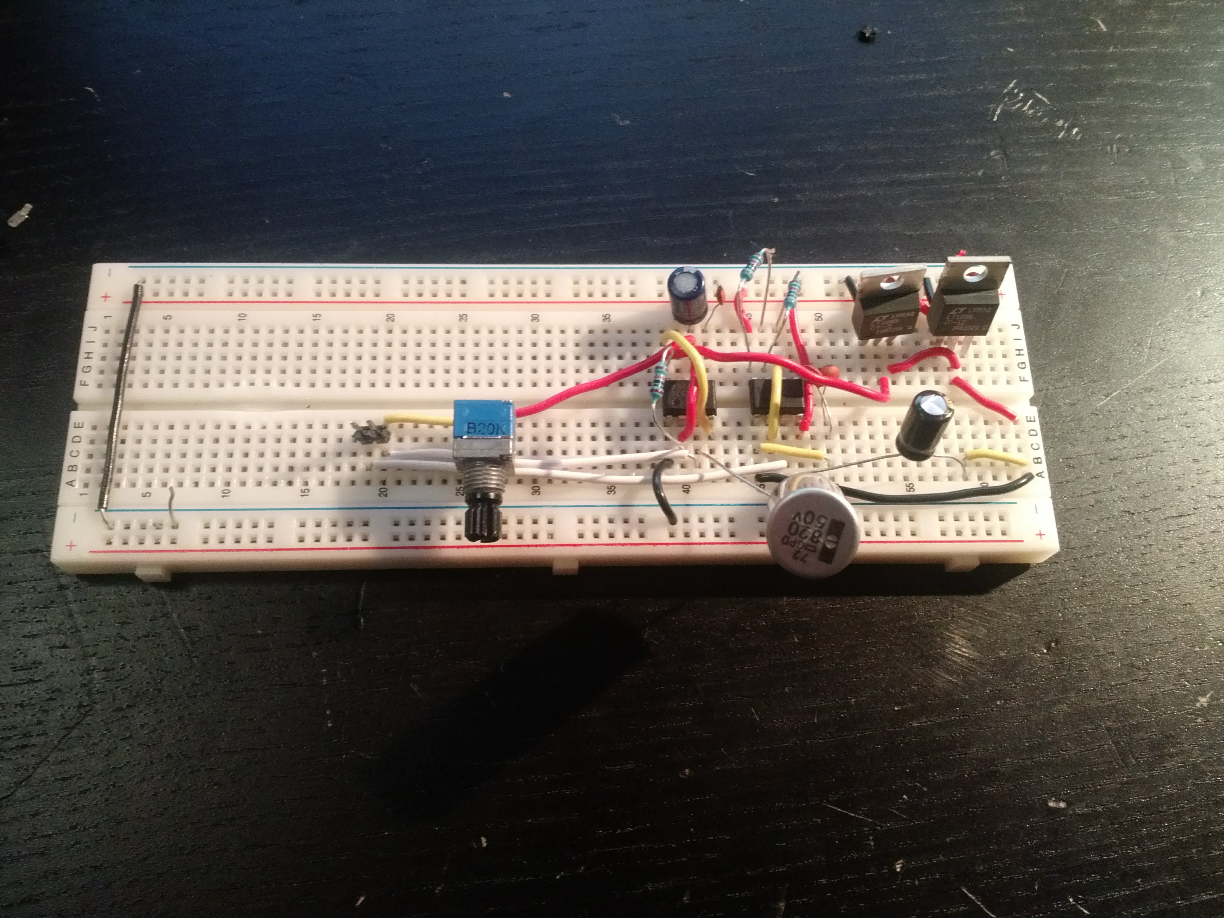
Here's what it outputs.
14V:
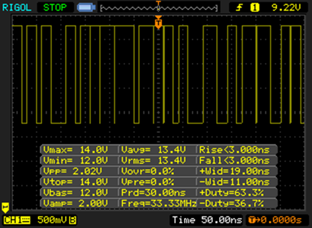
It’s close, but if you look carefully you'll see the frequency is somewhere greater than 33MHZ (I'm pretty sure this was my scope telling me it's unhappy), after a few cap taps we were free of this issue and all was well.
Here's the 5V output on the slow setting:
There's some difference in the waveform shapes, but the voltage range and frequency are nearly bang on. Hooray!
For the fast setting here's the result:
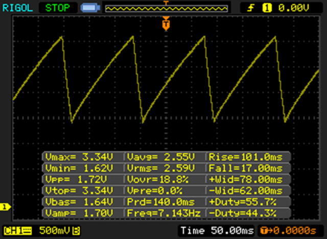
Once again things look pretty good! Though one weird thing I noticed was at the fastest setting we were only getting around 7Hz, we'd expect to get up to ~30Hz. Not a huge deal and hopefully it goes away once things are in a more robust PCB.
This is getting a bit long, so I'll split it up and finish up Analog in one more log.
Discussions
Become a Hackaday.io Member
Create an account to leave a comment. Already have an account? Log In.