 SUF
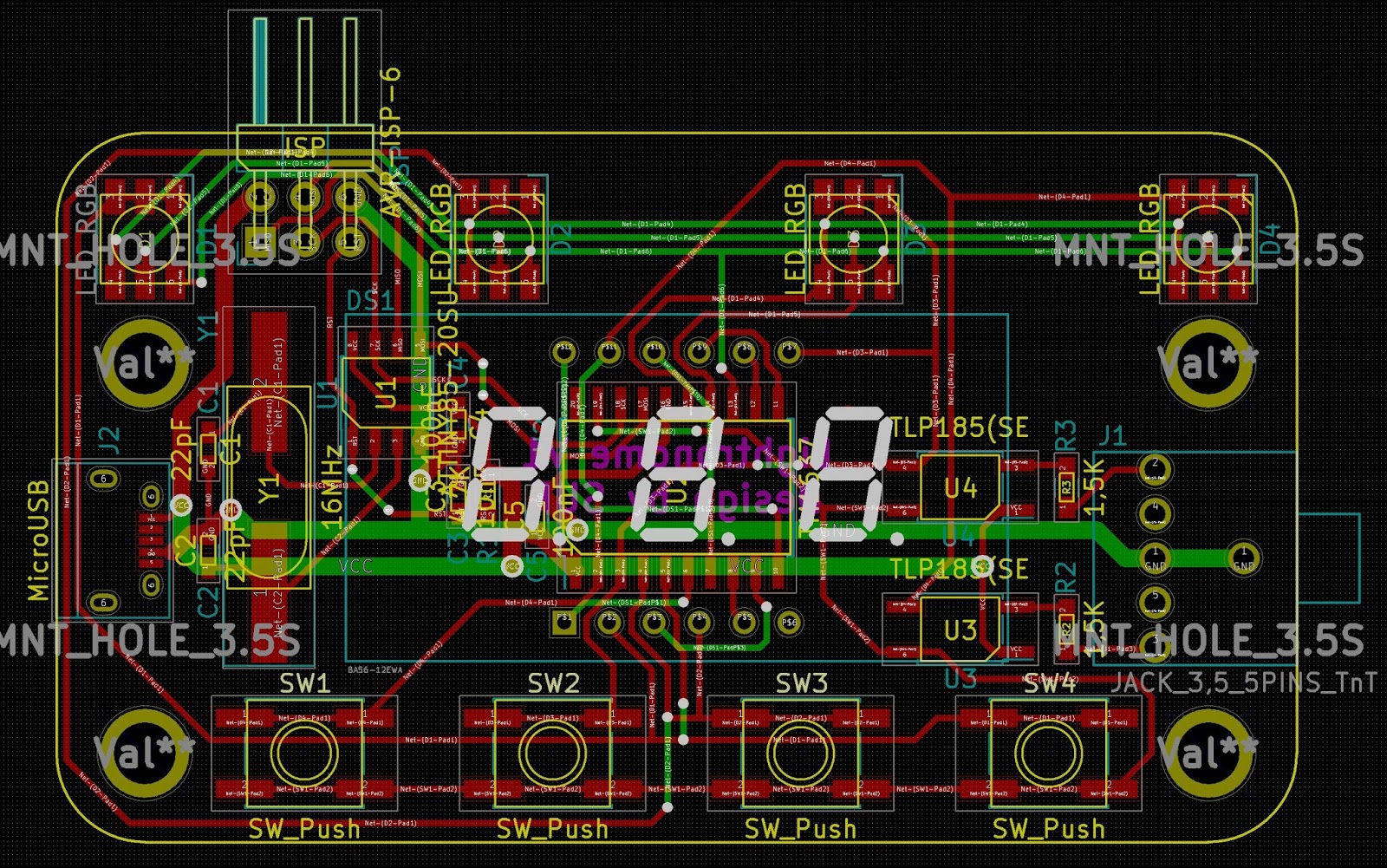
SUFBased on my breadboard design I created a schematic in KiCAD, designed the PCB and ordered from ALLPCB.
The board:
It arrived in a week:
Started to populate it - here comes the problems:
- I chosen a wrong size package for the ATTINY85, so I have to bend the pins to be able to solder in
- The micro USB connector wasn't far enough from the edge
- The 3.5 Jack had two missing holes.
Those was easily correctable.
So the build (without the display):
After resoldering the ATTINY for a few times, I was able to download the code, but nothing appeared on the display or the LEDs.
Scratching my head. Then I realized, that the ISP connector has all of the pins required to drive the TM1637. So I connected this external display to it:
It was working.
I started to measure the board, and instantly realized the problem.
The VCC and GND pins of the TM1637 was swapped. How this happened?
I mirrored the TM1637 part in the KiCAD. After this the GND pin went to the top of the drawing and the VCC to the bottom. After this I connected the power pins as usual. The VCC to the top and the GND to the bottom. IDIOT!!!!
Discussions
Become a Hackaday.io Member
Create an account to leave a comment. Already have an account? Log In.
Each time i design a board, something does not fit. Murphys law I gess :)
Are you sure? yes | no
I always blame the components!
Are you sure? yes | no
I mostly blame myself.
1. Bad component design, if I did it.
2. Why I didn't check the component before if it will fit.
Are you sure? yes | no
classic "I did that once and never again" mistakes :)
Are you sure? yes | no
Yepp, never until I forget this. :-D
Are you sure? yes | no