 Bharbour
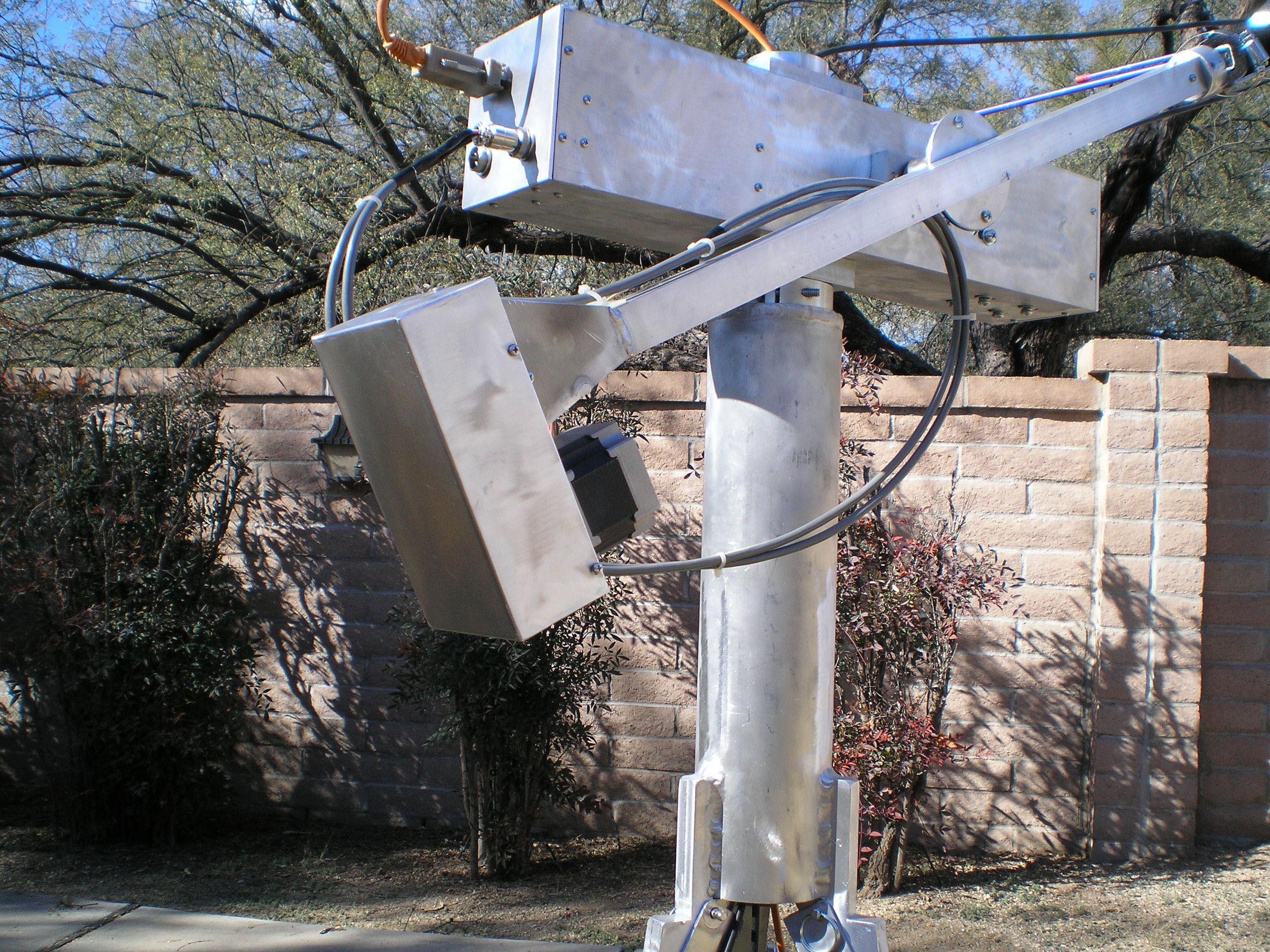
I fabricated the cover for the theta drive belt and home sensor this morning.
This is the complete mechanical system now. The tripod is interchangable with my previous version, avoiding one more piece to build. The complete system with the antenna is shown below.
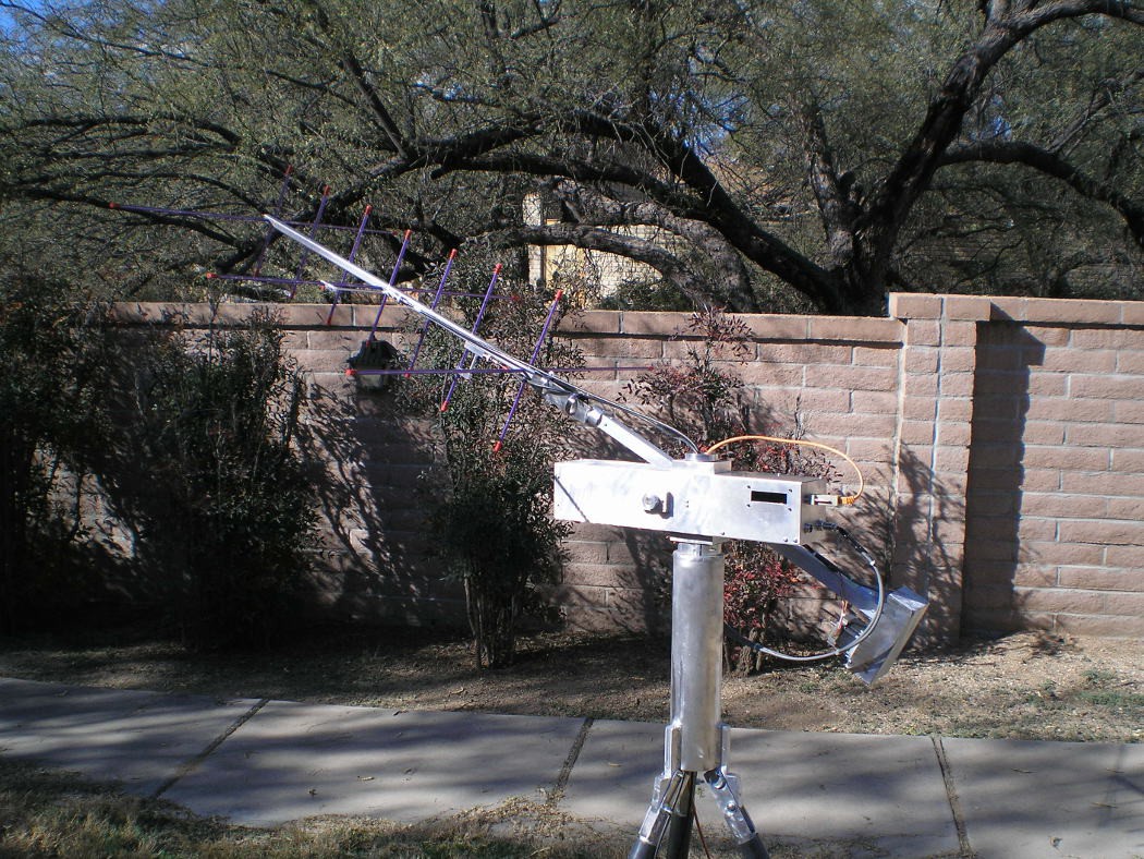
For size reference, the wall behind the rotator is about 5 or 5.5 feet tall.
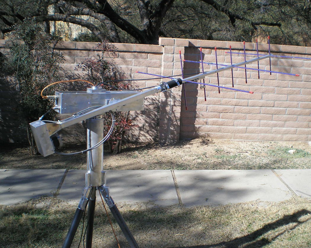
This shot shows the antenna and mount a little better. The antenna is an Arrowshaft Yagi, and the mount is about 6" of 1.5" angle welded to a piece of 1.5" bar stock. A shaft runs from the large pulley seen in previous pictures to the extreme right end of the elevation/theta arm. The antenna mount clamps to the shaft, allowing the step motor to rotate the antenna to accomodate the satellite tumbling in orbit.
The tripod body is a piece of 4" aluminum tube with an end plate welded to the top and the leg mounts welded to the bottom end. A clamp screwed to the top plate allows holding the azimuth tube in a fixed position, so that the whole upper assembly rotates. The legs on the tripod are made to fold up after pulling out the pins just below the end of the body tube.
Cables will go down the center of the azimuth mast tube and the tripod body. Software limits the azimuth rotation to 359 degrees, so twisting up the cables is not a problem.
Discussions
Become a Hackaday.io Member
Create an account to leave a comment. Already have an account? Log In.