 Alex Rich
Here is a rundown of the steps I took in CAD to create the handle. You can get way fancier for sure, but sometimes I think using advanced features like lofts and sweeps ends up being uglier than simple clean linear extrudes.
Step 1: Sketch side profile of stickvise in one sketch, then in a second sketch draw the handle shape. The handle shape is loosely based on my pen sketch, but really is just eyeballed.
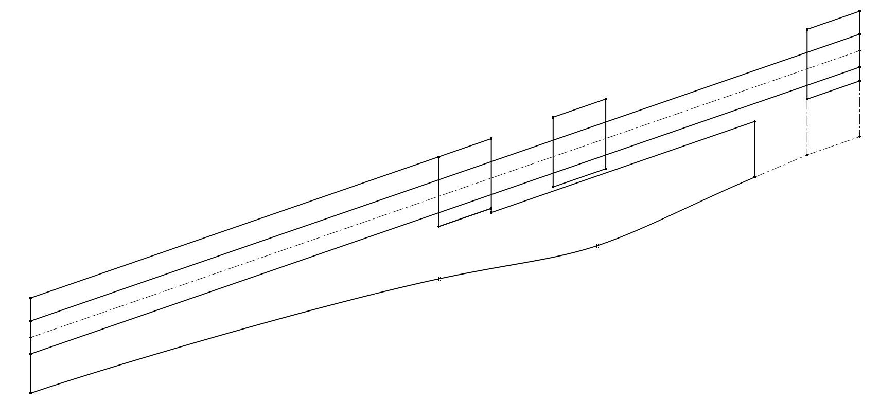
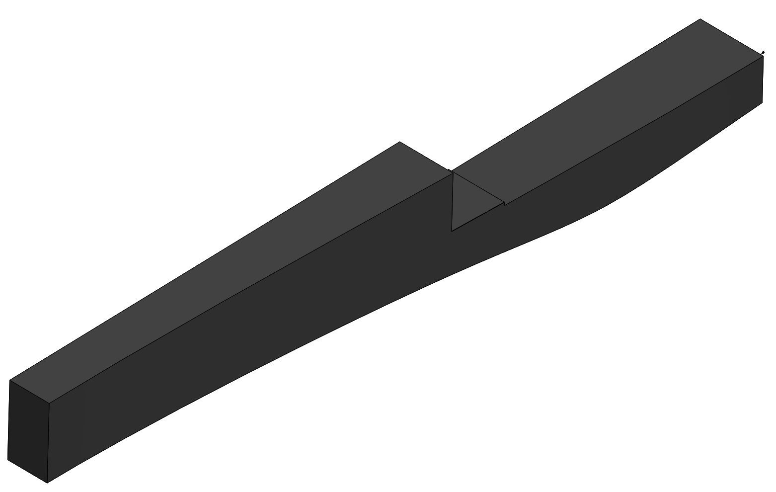
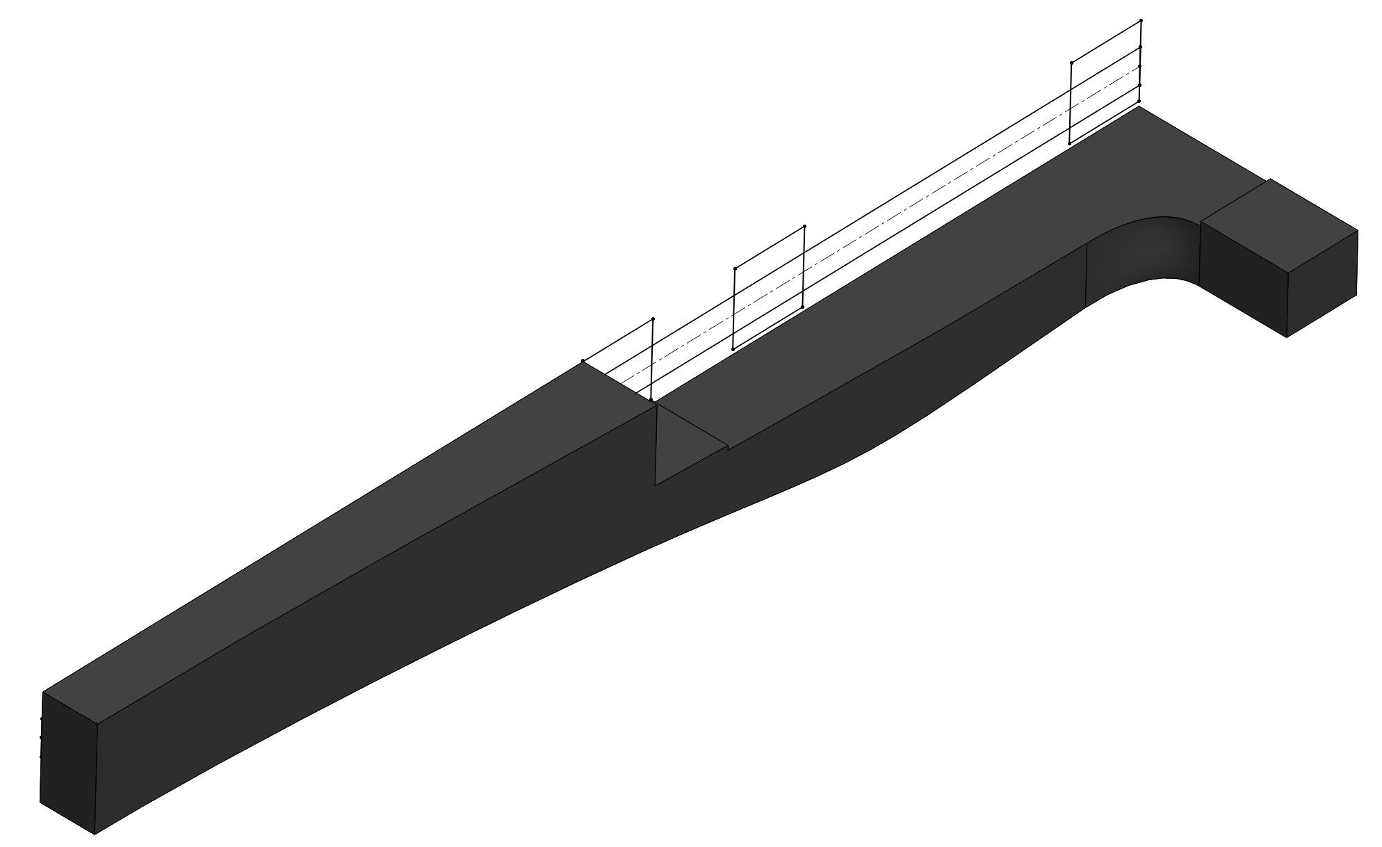
Step 2: extrude the handle shape in one direction. Since this will be a symmetrical handle, I will only create one side of it and then use a mirror feature at the very end to finish it.

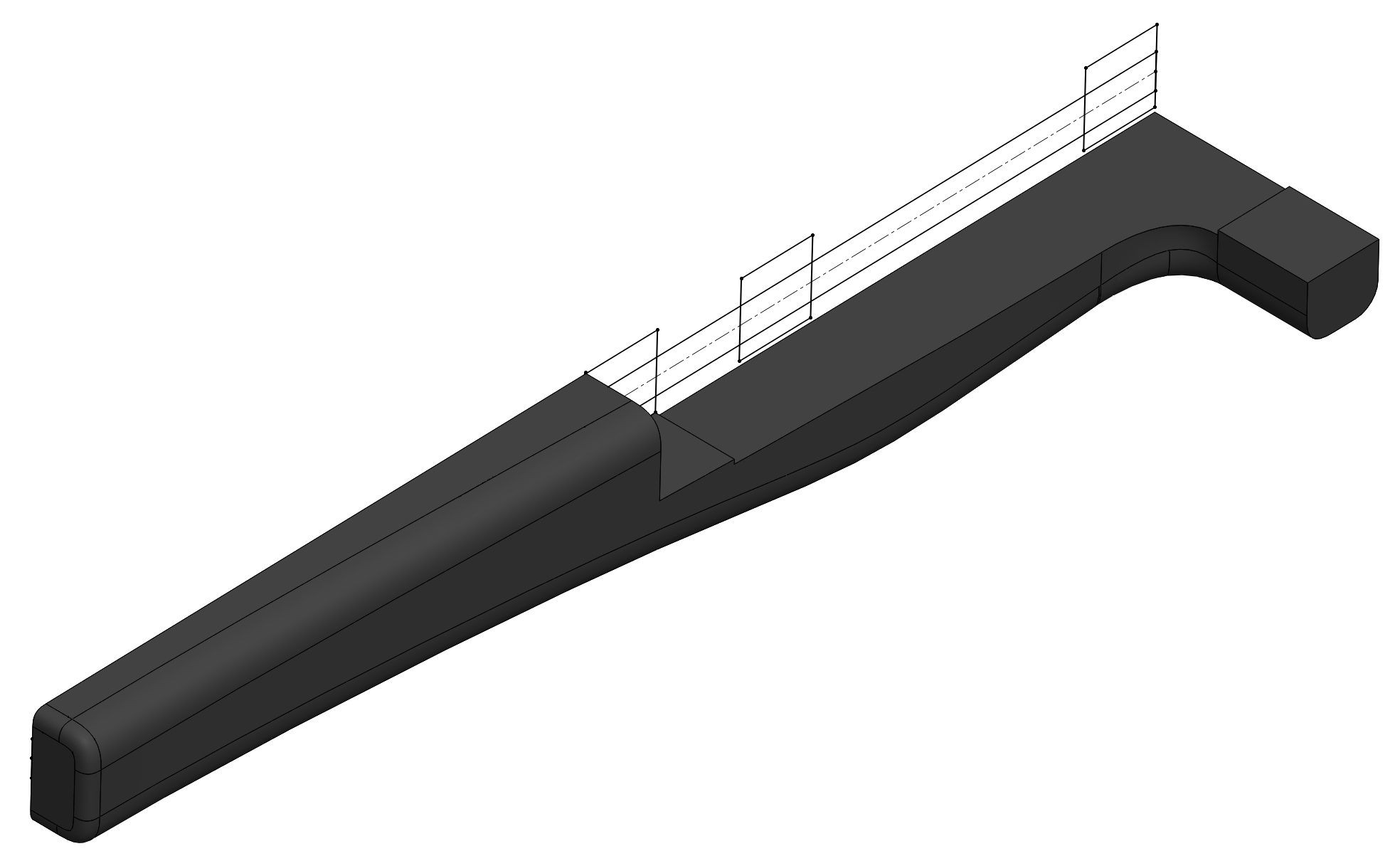
Step 3: Sketch the top profile of the handle and then cut extrude. This curve was also eyeballed, it is just a single spline that has a gentle curve to it.
Step 4: Create the piece that will eventually attach to Stickvise's fixed jaw.
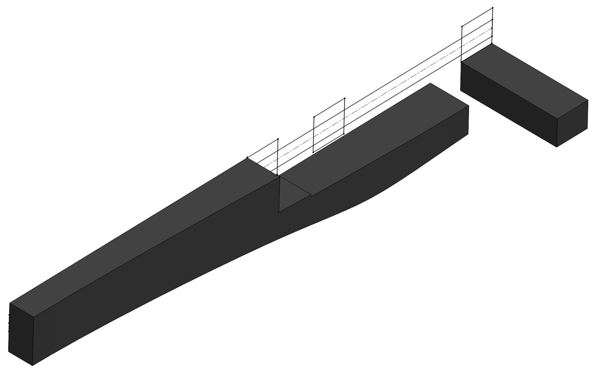
Step 5: This is a subtle thing, but I cut a section in the middle of the fixed jaw that is .03" deep. This will make more sense in the next step, I am basically creating an area to join the two pieces together using a loft. This is because the handle has .03" of clearance from the bottom of Stickvise so there is no rubbing when you fire the arrow.
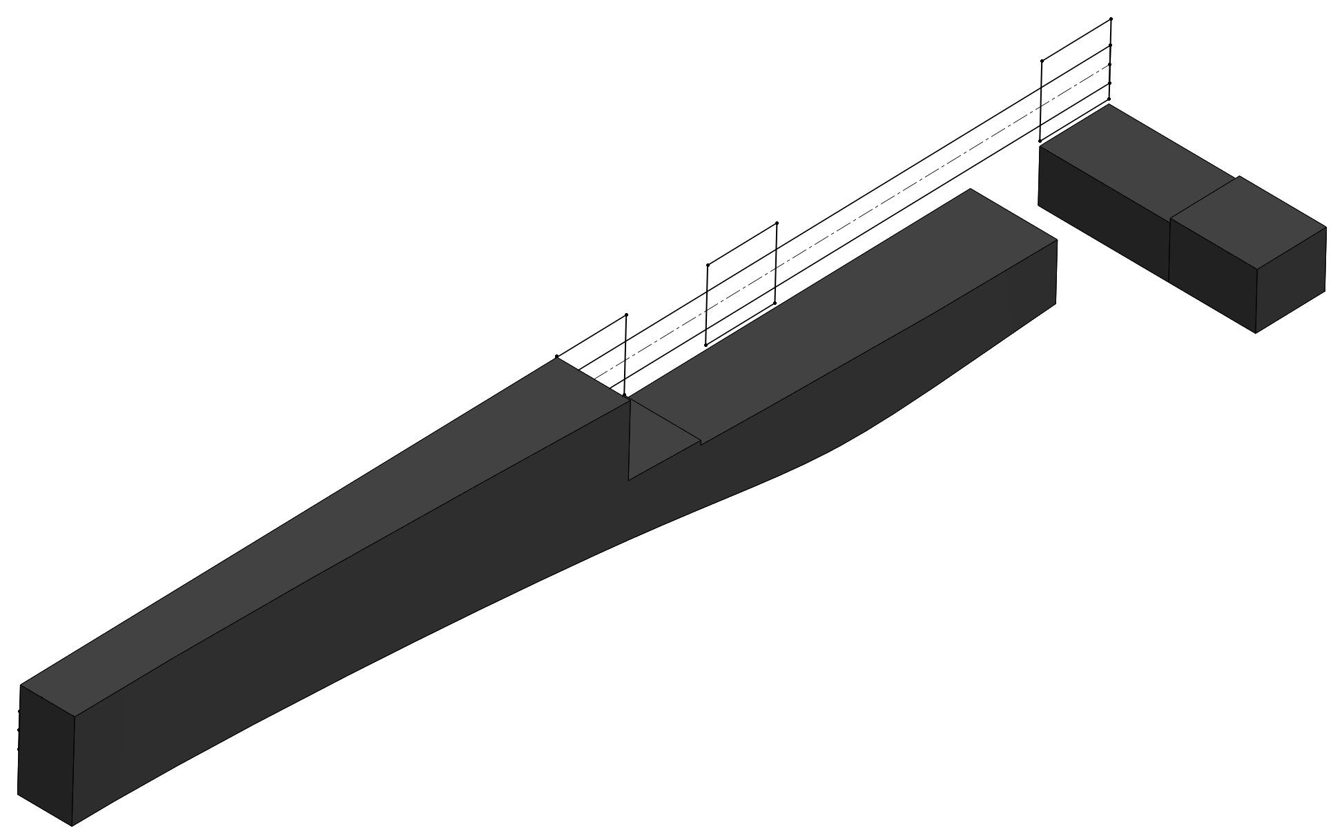
Step 6: Loft the two pieces together. You can see the top surface is one continuous plane. If I had not made the cut in step 5 the top surface would have a small wave in it. No big deal either way, but I like keeping surfaces which are intended to be planar, planar (if that makes any sense).
Step 7: Fillet everything as desired. I used curvature continuous fillets, but for 3d printing you can't tell the difference anyway especially on small fillets like these. Circular fillets would look fine.
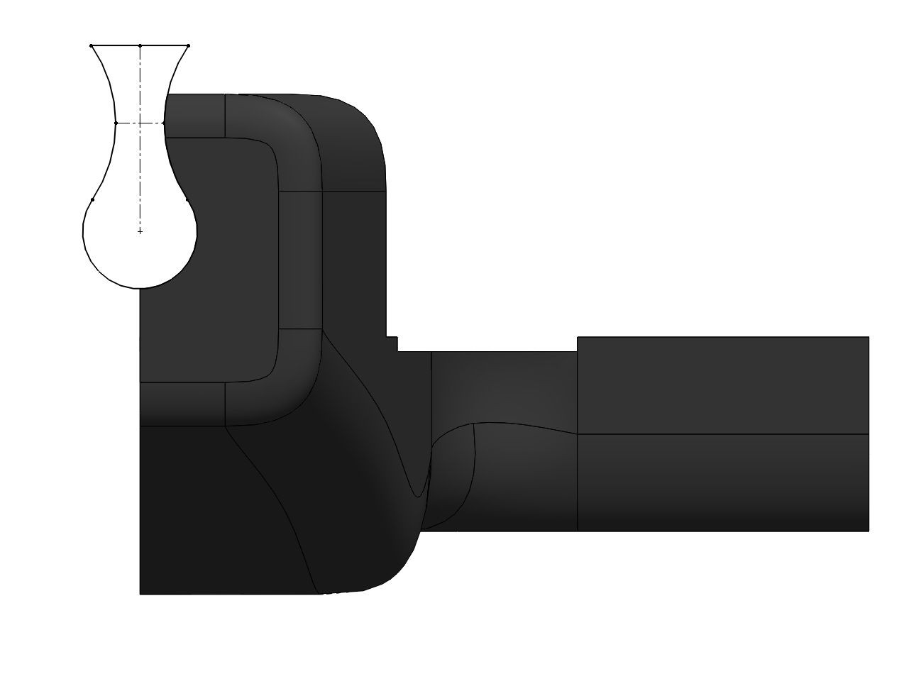
Step 8: Cut a hole for the shaft of Stickvise. The reason for the hourglass shape leading up is to prevent the need for support material in the 3d print while still capturing the shaft securely. I used a 1:1 fit which in my experience is fine for 3d prints because the plastic flexes a little bit. If necessary I can also ream this hole a bit with a drill bit to get the fit better in post processing.
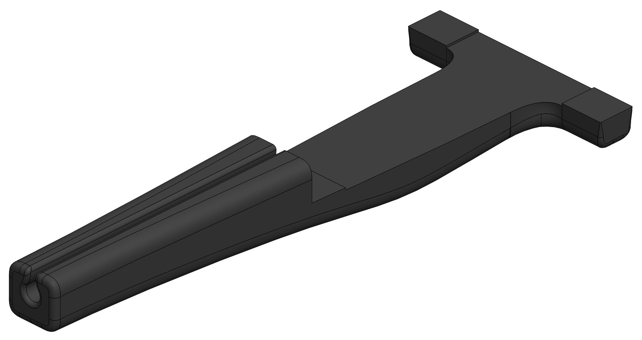
Step 9: Mirror the body to form the final handle. This is the meat of the design, all that is left is adding mounting holes and a trigger. Will try to show the CAD process for that as well.
Discussions
Become a Hackaday.io Member
Create an account to leave a comment. Already have an account? Log In.