 Moritz Walter
Happy new year everybody!
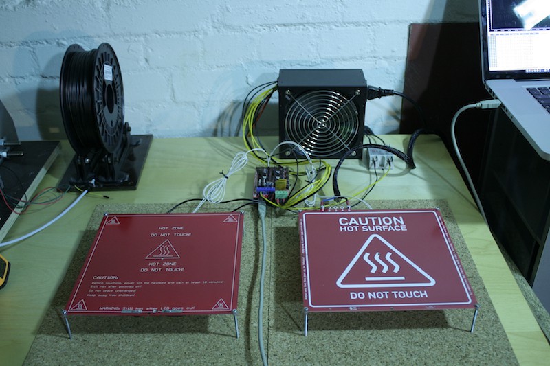
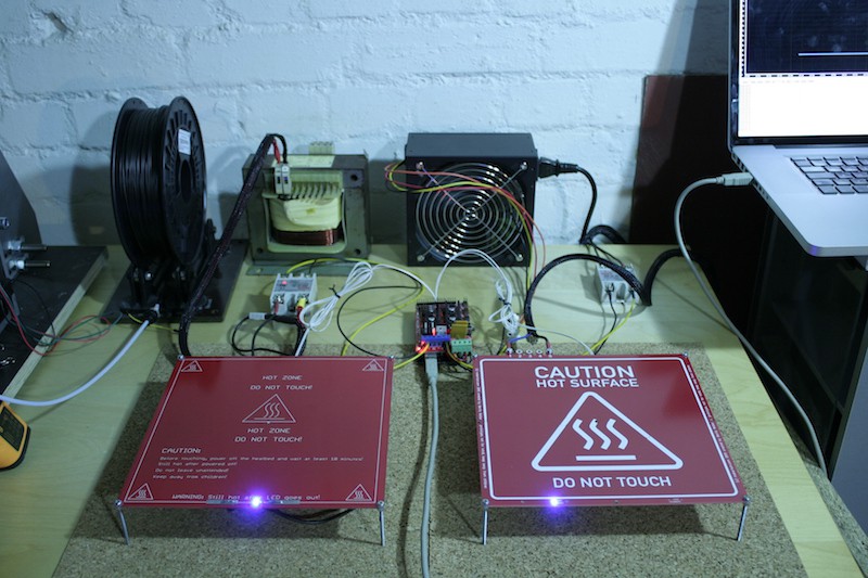
Before and after excessively celebrating a new, awesome year with the people of the Attraktor Makerspace, I had time to setup a small testing rig for more thorough testing of the heated beds. @Alex Rich suggested recording a temperature graph to show the performance in comparison to the regular MK2 heated bed, which will be covered in this log, however, this is not meant as a competition. Josef Prusa, who has done a great job designing the MK2 in a way so it would under no circumstances experience a thermal runaway, which is very much the harder thing to do without employing additional fuses etc.
Comparison with MK2 at 12V DC
The setup:
Contestants: MK2 (12 V version) and mains voltage heated bed
PSU: modified 12 V AC 500W ATX, dedicated to heating the MK2
Controller: Arduino 2560 clone and RAMPS 1.4
Wiring: MK2 attached heated bed port of RAMPS / 230 V AC heated bed attached to extruder port of RAMPS via FOTEK SSR-40 DA
Temperature sensors: EPCOS 100k
Starting temperature: 21 °C
Target temperature: 110 °C
Inital temperature difference (max): 1 °C
Additional info: PID autotune with 8 cycles performed before on both heaters, heaters placed on cork mat offset by M3x50mm screws, plain PCB with no printing plate attached to heated beds
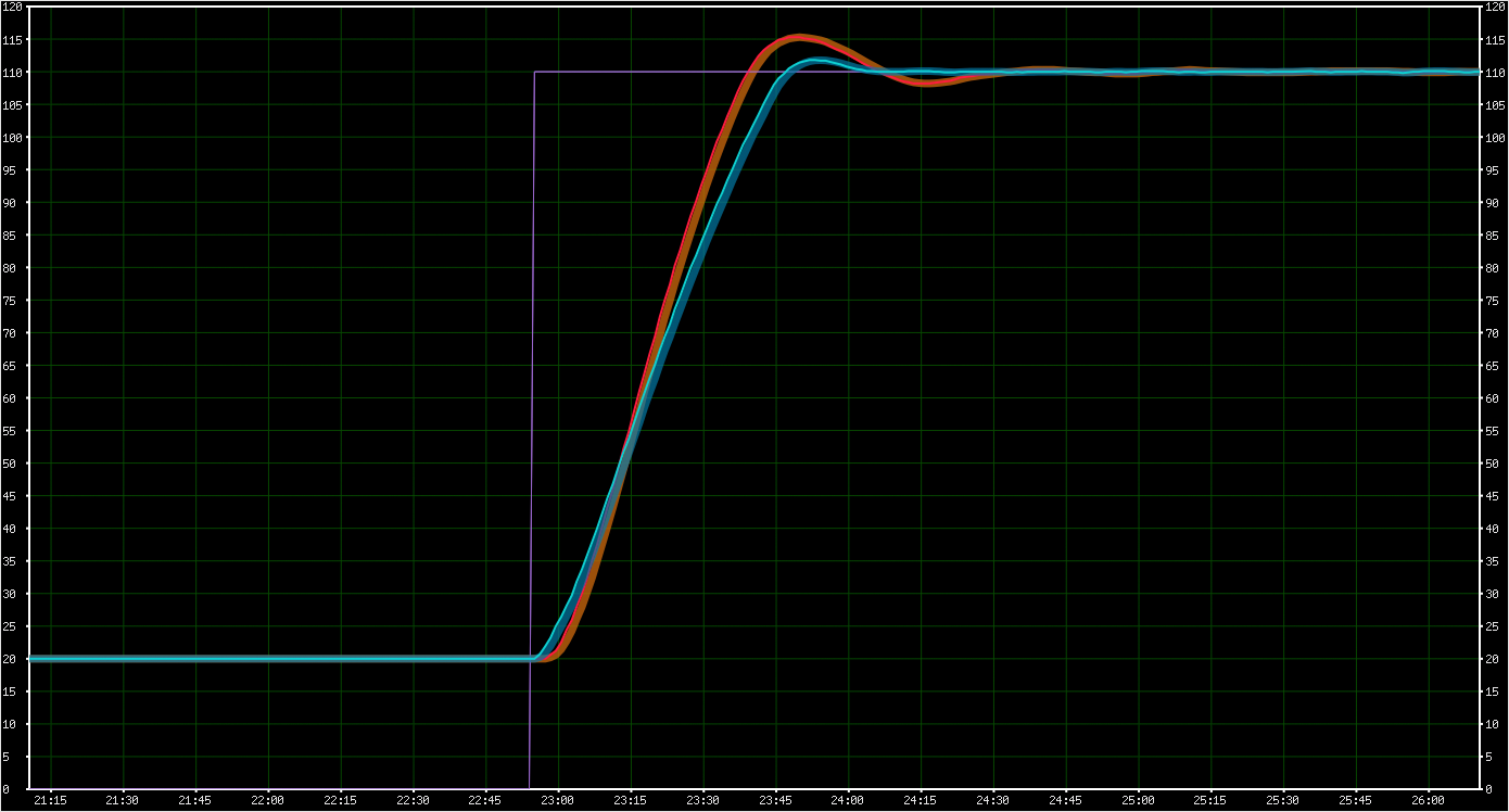
With this setup, I ran this short GCODE snippet from Repetier host, which starts the heating for both heated beds simultaneously:
M104 S110
M140 S110
Repetier Host was then used to graph the temperature curves from both heaters, rendering the following curve:
RED: mains heated bed at 230 V AC
BLUE: MK2 heated bed at 12 V DC
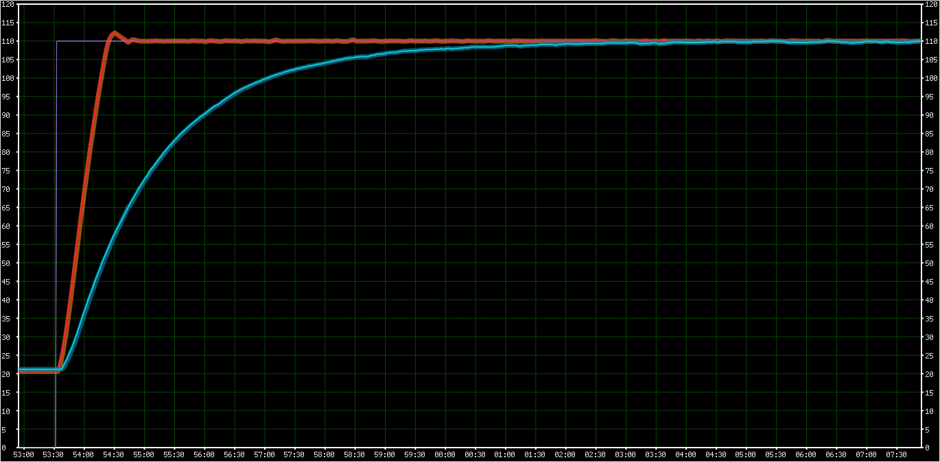
The mains voltage heated bed reaches stable printing temperature after about 1:40 minutes while the MK2 almost reaches 110 °C after about 10 minutes but then struggles to hold the temperature. So, in terms of heating performance, this is a win for the mains voltage heated bed, but it also becomes clear why it really needs a thermal fuse: Whereas the MK2 is designed to passively max out at 110 °C, the mains voltage heated bed is just powerful enough to run away and shoot through the roof, so safe operation requires an active mechanism to let it max out at a certain temperature, which is the thermal fuse.
Comparison with MK2 at 24V AC "overdrive"
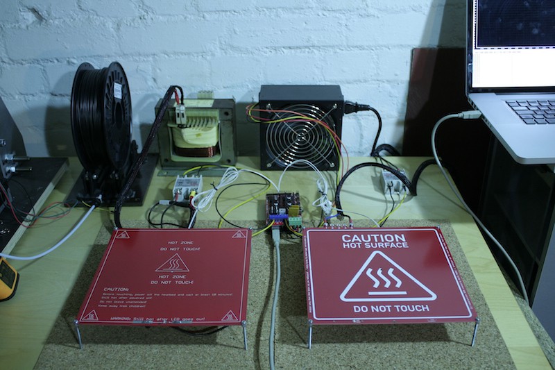
The setup:
Contestants: MK2 (12 V version) and mains voltage heated bed
PSU: modified 12 V AC 500W ATX, dedicated to Arduino and a 24 V 500 V AC transformer dedicated to heating the MK2
Controller: Arduino 2560 clone and RAMPS 1.4
Wiring: MK2 attached extruder port of RAMPS via FOTEK SSR-40 DA / 230 V AC heated bed attached to heated bed port of RAMPS via FOTEK SSR-40 DA
Temperature sensors: EPCOS 100k
Starting temperature: 21 °C
Target temperature: 110 °C
Inital temperature difference (max): 1 °C
Additional info: PID autotune with 8 cycles performed before on both heaters, heaters placed on cork mat offset by M3x50mm screws, plain PCB with no printing plate attached to heated beds
And again the GCODE snippet to initiate the race:
M104 S110
M140 S11
And Repetier Host renders the following curve:
RED: MK2 heated bed at 24 V AC
BLUE: mains heated bed at 230 V AC
As expected, in this "overdrive" mode, the performance of both heaters is quite similar, since both heaters are supposed to output about 500 watts of heat, they both finish heatup in about 1:40 minutes. The 20% manufacturing (aka planning) error in the mains powered heated bed noticeably decreases performance, but it also becomes clear that even though PID was properly tuned on both heaters, the MK2 overshoots a bit more. This might be due to the single sided heating traces, whereas the traces run on the top while the temperature sensor is attached to the bottom. The double sided layout of the mains voltage PCB provides some "symmetry" of temperature. Note that the MK2 is not designed to run at 500W, so it does not have pads for a thermal fuse.
Other observations: Breathing
One very noteable difference between the two beds is however totally unrelated to the involved voltages. It's the breathing of the heated bed, and I noticed how extreme it is when I went through the photos I had taken for this log:

The MK2 heated bed is a compound of one layer of FR4 and one layer of copper on top of it, so the thermal expansion of the copper causes the heated bed to bend. You might already have observed this when dealing with improperly calibrated PID settings or BANG BANG controlled heated beds where it causes prints to come out wavy.
Since the mains voltage heated bed is a sandwich with copper on both sides of the FR4, it also doesn't breathe, thus - besides faster heatup time - is expected to also contribute to the overall printing quality.
More testing
Since the testing setup is in place now, I'll also start the 130° C 30 days endurance test on the mains voltage heated bed. This is the next important step to ensure that this prototype is safe to be tested by betatesters, which may apply in the comments on this project.
Discussions
Become a Hackaday.io Member
Create an account to leave a comment. Already have an account? Log In.
Nice! So your graph shows you are equivalent to the overdrive 24 VDC bed, is the main advantage of yours just a lower price because you don't need the big transformer? The flex in the MK2 is significant as well, interesting that you caught that. I always questioned laminating so many different materials together. This effect is probably even worse on the beds with a thin sheet of aluminum glued to the top.
Are you sure? yes | no
I had used the overdriven MK2 for many years and found the 500W just right, so I designed the mains voltage bed to that spec. Price/weight/size are surely the most significant advantages, and then there is a thermal fuse, less to no breathing/flex, faster thermistor response, more mounting holes, insulated screw terminals, LED cover, etc. Also, and this is funny, I think it's safe to say this heated bed is noticeably (like ~10%) more energy efficient than using a MK2 together with a switched PSU (will measure that, soon).
Are you sure? yes | no
This is what I've been looking for in the last weeks! I like to have my Y-carriage on a Prusa as light as possible and also be able to switch glass sheets fast between prints when printing on multiple machines, so that I can wait for the pieces to cool while starting another print job on a new sheet of glass. The MK2 is slow to heat and when using multiple machines this becomes a drag. Using an extra source is too complicated and not an elegant solution, I'm trying to get rid of this. While using a silicon heatbed on mains there is the drawback that I have to stick it to an aluminium plate and then use the glass tops, this adds weight, but your PCB heatbed eliminates the issue as the PCB offers support also. Since the printers should be observed during their printing time anyway, safety is partially taken care of, but of course the more robust the PCB design the better. Count me in when it's done or for any kind of beta testing! Have a happy new year!
Are you sure? yes | no
Hey! Thanks! Glad you like the idea! I'll notify you as soon as the beta testing kits become available. Happy new year to you, too!
Are you sure? yes | no