Moritz Walter
-
Temperature graph, breathing, more testing
01/01/2016 at 23:43 • 4 commentsHappy new year everybody!
Before and after excessively celebrating a new, awesome year with the people of the Attraktor Makerspace, I had time to setup a small testing rig for more thorough testing of the heated beds. @Alex Rich suggested recording a temperature graph to show the performance in comparison to the regular MK2 heated bed, which will be covered in this log, however, this is not meant as a competition. Josef Prusa, who has done a great job designing the MK2 in a way so it would under no circumstances experience a thermal runaway, which is very much the harder thing to do without employing additional fuses etc.
Comparison with MK2 at 12V DC
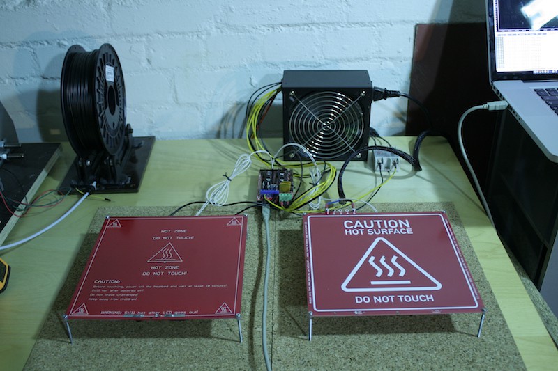
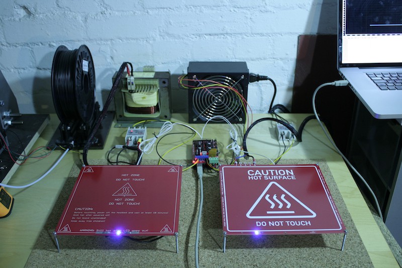
The setup:
Contestants: MK2 (12 V version) and mains voltage heated bed
PSU: modified 12 V AC 500W ATX, dedicated to heating the MK2
Controller: Arduino 2560 clone and RAMPS 1.4
Wiring: MK2 attached heated bed port of RAMPS / 230 V AC heated bed attached to extruder port of RAMPS via FOTEK SSR-40 DA
Temperature sensors: EPCOS 100k
Starting temperature: 21 °C
Target temperature: 110 °C
Inital temperature difference (max): 1 °C
Additional info: PID autotune with 8 cycles performed before on both heaters, heaters placed on cork mat offset by M3x50mm screws, plain PCB with no printing plate attached to heated beds
![]()
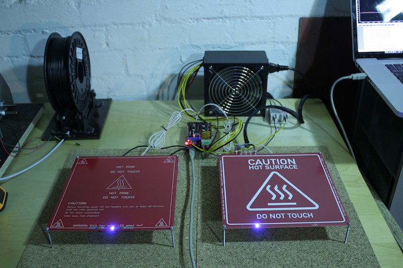
With this setup, I ran this short GCODE snippet from Repetier host, which starts the heating for both heated beds simultaneously:
M104 S110
M140 S110
![]()
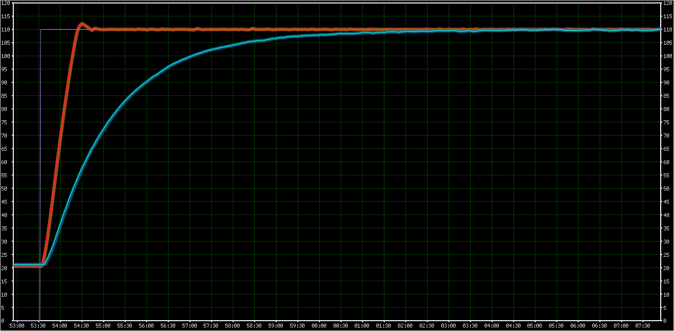
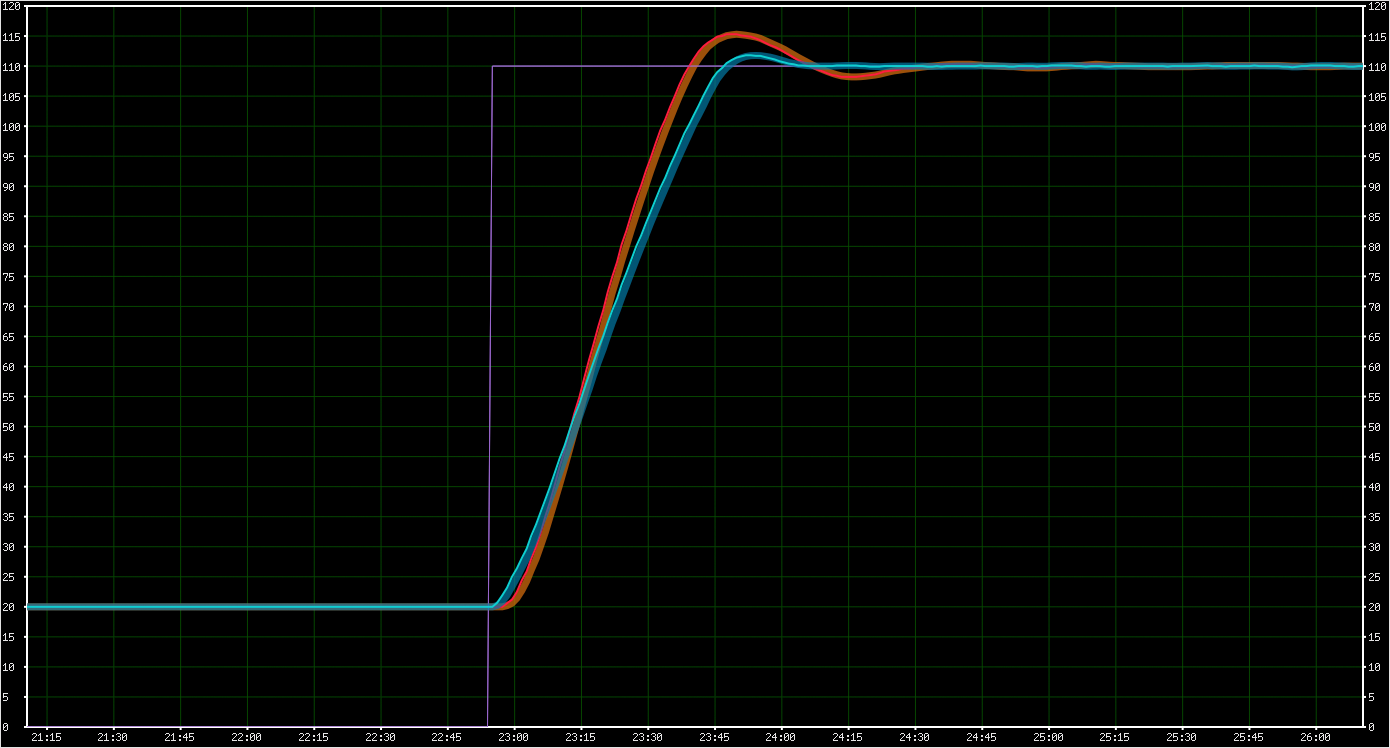
Repetier Host was then used to graph the temperature curves from both heaters, rendering the following curve:
RED: mains heated bed at 230 V AC
BLUE: MK2 heated bed at 12 V DC
![]()
The mains voltage heated bed reaches stable printing temperature after about 1:40 minutes while the MK2 almost reaches 110 °C after about 10 minutes but then struggles to hold the temperature. So, in terms of heating performance, this is a win for the mains voltage heated bed, but it also becomes clear why it really needs a thermal fuse: Whereas the MK2 is designed to passively max out at 110 °C, the mains voltage heated bed is just powerful enough to run away and shoot through the roof, so safe operation requires an active mechanism to let it max out at a certain temperature, which is the thermal fuse.
Comparison with MK2 at 24V AC "overdrive"
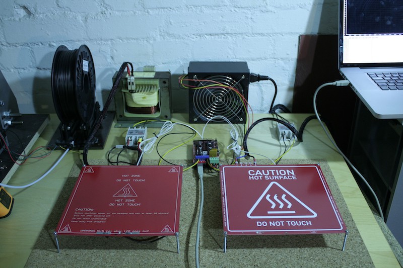
The setup:
Contestants: MK2 (12 V version) and mains voltage heated bed
PSU: modified 12 V AC 500W ATX, dedicated to Arduino and a 24 V 500 V AC transformer dedicated to heating the MK2
Controller: Arduino 2560 clone and RAMPS 1.4
Wiring: MK2 attached extruder port of RAMPS via FOTEK SSR-40 DA / 230 V AC heated bed attached to heated bed port of RAMPS via FOTEK SSR-40 DA
Temperature sensors: EPCOS 100k
Starting temperature: 21 °C
Target temperature: 110 °C
Inital temperature difference (max): 1 °C
Additional info: PID autotune with 8 cycles performed before on both heaters, heaters placed on cork mat offset by M3x50mm screws, plain PCB with no printing plate attached to heated beds
![]()
And again the GCODE snippet to initiate the race:
M104 S110
M140 S11
![]()
And Repetier Host renders the following curve:
RED: MK2 heated bed at 24 V AC
BLUE: mains heated bed at 230 V AC
![]()
As expected, in this "overdrive" mode, the performance of both heaters is quite similar, since both heaters are supposed to output about 500 watts of heat, they both finish heatup in about 1:40 minutes. The 20% manufacturing (aka planning) error in the mains powered heated bed noticeably decreases performance, but it also becomes clear that even though PID was properly tuned on both heaters, the MK2 overshoots a bit more. This might be due to the single sided heating traces, whereas the traces run on the top while the temperature sensor is attached to the bottom. The double sided layout of the mains voltage PCB provides some "symmetry" of temperature. Note that the MK2 is not designed to run at 500W, so it does not have pads for a thermal fuse.
Other observations: Breathing
One very noteable difference between the two beds is however totally unrelated to the involved voltages. It's the breathing of the heated bed, and I noticed how extreme it is when I went through the photos I had taken for this log:
![]()
The MK2 heated bed is a compound of one layer of FR4 and one layer of copper on top of it, so the thermal expansion of the copper causes the heated bed to bend. You might already have observed this when dealing with improperly calibrated PID settings or BANG BANG controlled heated beds where it causes prints to come out wavy.
Since the mains voltage heated bed is a sandwich with copper on both sides of the FR4, it also doesn't breathe, thus - besides faster heatup time - is expected to also contribute to the overall printing quality.
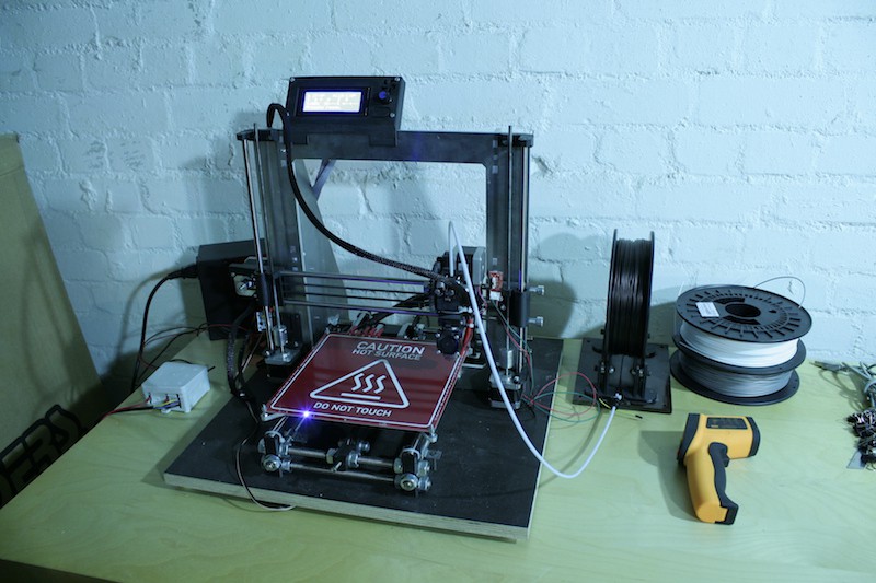
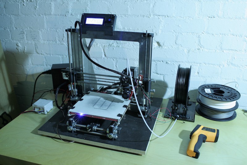
More testing
Since the testing setup is in place now, I'll also start the 130° C 30 days endurance test on the mains voltage heated bed. This is the next important step to ensure that this prototype is safe to be tested by betatesters, which may apply in the comments on this project.
-
Soldering, wiring, first power up & testing
12/30/2015 at 00:53 • 7 commentsBack from winter holiday, I found some nice blue 0805 smd LEDs in the mailbox, along with some SSRs, fuse holders, RAMPs boards and some other stuff. So yes, it's finally time to test drive a heated bed from the first batch.
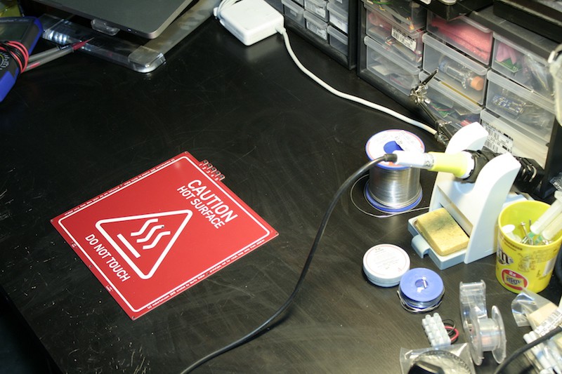
Soldering
![]()
On this first board, I'll only solder the LED circuit and bridge all fuses to test the PCBs thermal stability only. Sorry for the messed up macro shots.
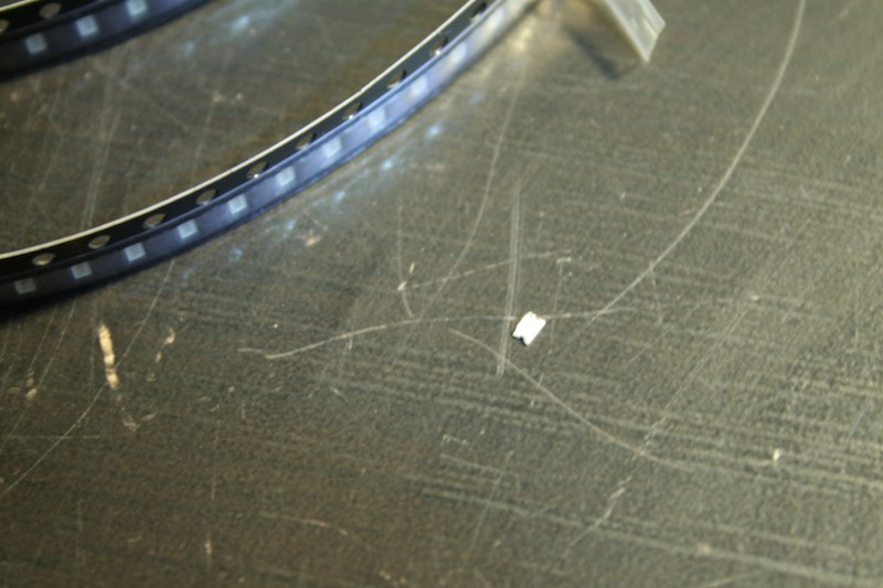
![]()
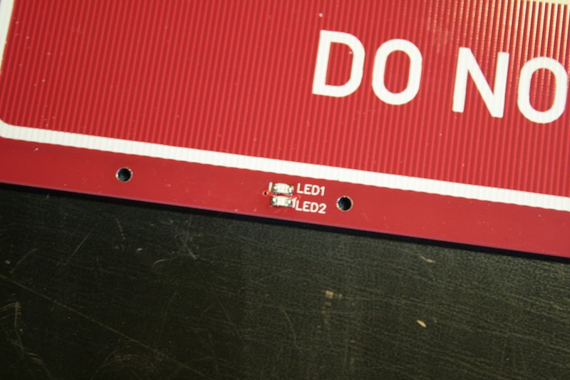
The 0805 LEDs go to the top side..
![]()
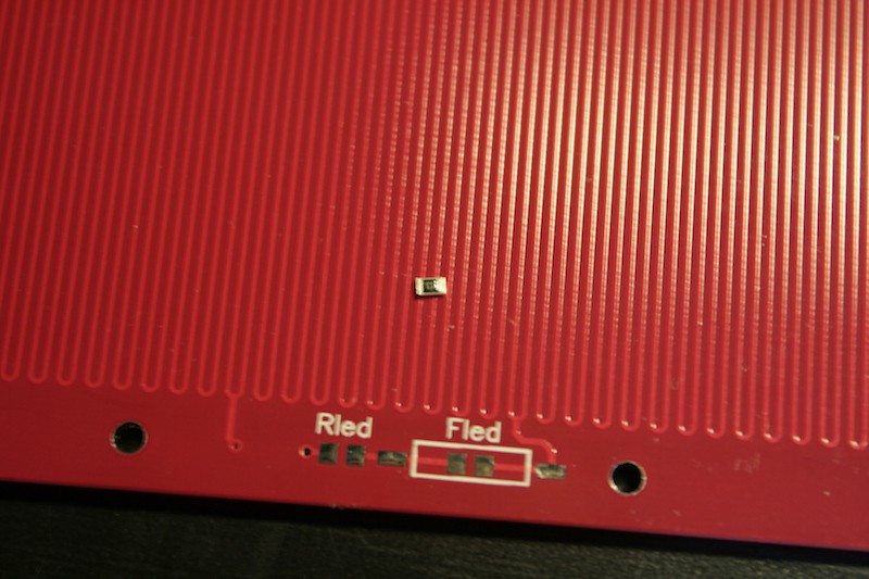
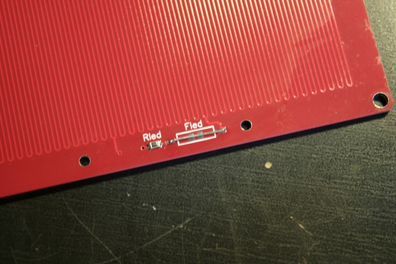
..while the current limiting resistor..
![]()
..goes to the bottom, next to the bridged fuse. Note that there are pads for solder bridging, but I didn't use since I want to install the picofuse lateron.
![]()
Wiring
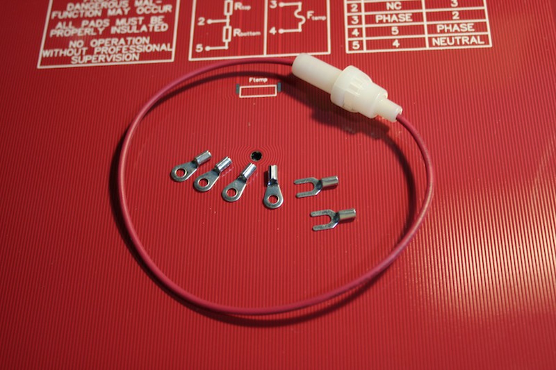
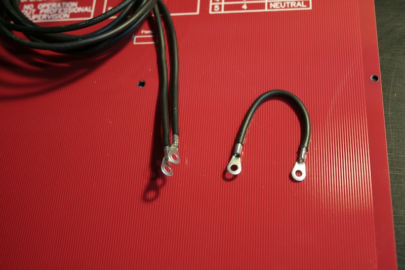
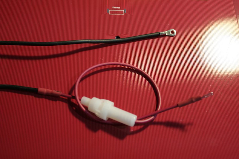
Next step ist preparing the wiring, mostly attaching and insulating cable lugs and inserting the fuse holder.![]()
Also, we need a little bridging wire to bridge the pad from the fuse to the phase pad.
![]()
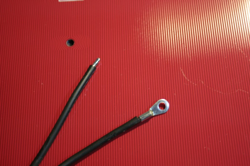
The picture below shows the neutral wire, it goes from the neutral pad directly to the neutral connector of the mains line:
And the next picture shows the phase wire with the fuse and the fork cable lug for the SSR, the ring cable lug connects to the phase pad on the PCB.![]()
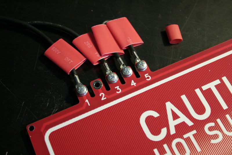
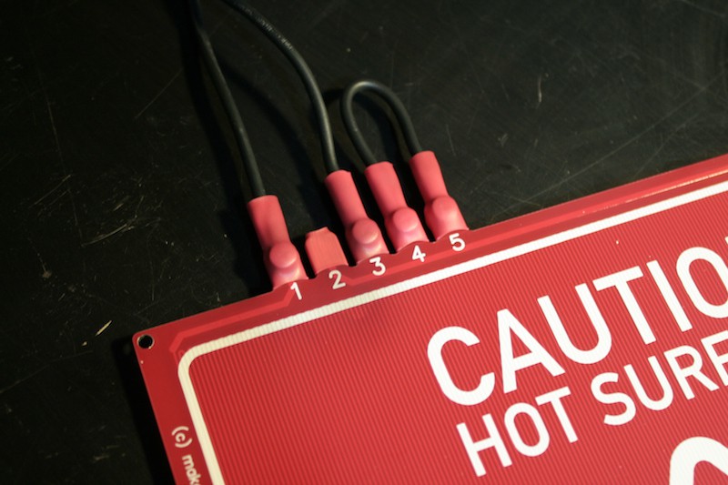
For the 230V~ wiring, we need 4 M3x5mm screws, 8 M3 washers and some heatshrink tube, the center pad remains unconnected but of course needs to be insulated:![]()
![]()
After the screws are tightened, the tube is shrinked over the connections to insulate them safely. High quality heatshrink tube is vital here. Since having the board house mill out 5 fingers from the board is basically free, this is actually a flush and economic alternative to clunky screw terminals.
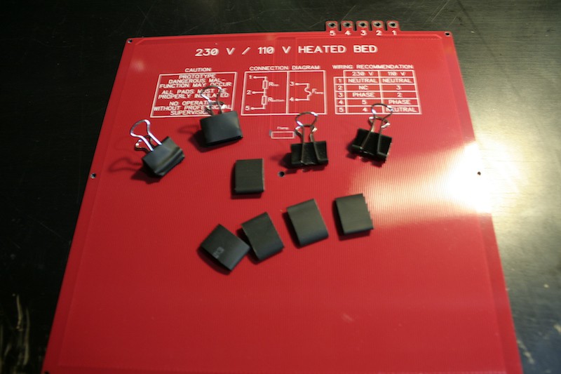
Another important step is insulating the foldback clamps that are traditionally used to clamp borosilicate glass plates or PEI (or whatever) to the heated bed. This is absolutely necessary, since the sharp edges of the foldback clamps could scratch of the soldermask and then conduct dangerous mains voltage. I'm using pieces of large diameter heatshrink tube here to insulate standard foldback clamps. I hope I'll find a better solution to this in the future.![]()
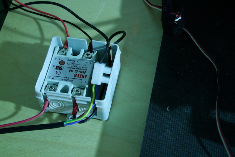
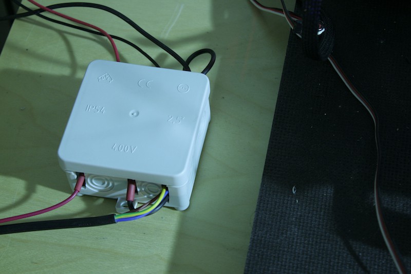
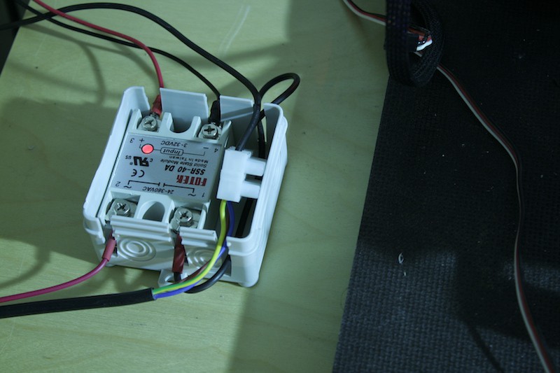
The wiring of the SSR will be documented in the future. If you don't know how to do it, you probably shouldn't do it. It's something I believe can only be done in one way and everybody who is actually supposed to do it knows how to do it :) I also had trouble fitting all the cables in one frame. However, since the SSR has mains voltage on the connectors, of course it needs to be sealed away safely. I used a standard IP54 distribution box:![]()
![]()
I love those IP54 boxes. Did you know that an Arduino UNO fits into it just perfectly? They're also cheap and available in many colors :D
![]()
First power up
Since we're not dealing with nice 3.3V logic levels here, bit of faith is required for this step. So I hooked everything up, attached a thermistor to the center of the heated bed using kapton tape and thermal compound, installed the heated bed and powered up the printer. Reading reasonable temperature values of the controller, I then carefully set the heated bed to 30 °C. For a few seconds, both the SSR and the blue led on the heated bed flashed.
![]()
I went on with 40 °C. Still none of the apocalyptic events I was prepared for seemed to happen.
![]()
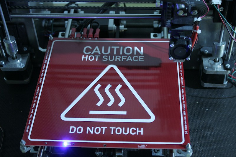
Ok, that made me confident, I started the preheating program to bring the bed to 110 °C.
![]()
Whooo, the temperature ramps up. Still no apocalypse. But the heatup time is much shorter than expected. It's only a few seconds. The insulated clamps also work nicely on the new heated bed:
![]()
Testing
With this up and running, I will now start testing the thermal stability of the PCBs. I'll run this first board at 110 °C for 30 days continuously to see if the FR4, copper traces, solder mask or silkscreen degenerate in any way. More testing setups for testing heatup/cooldown cycles and extrem temperatures will follow the next days.
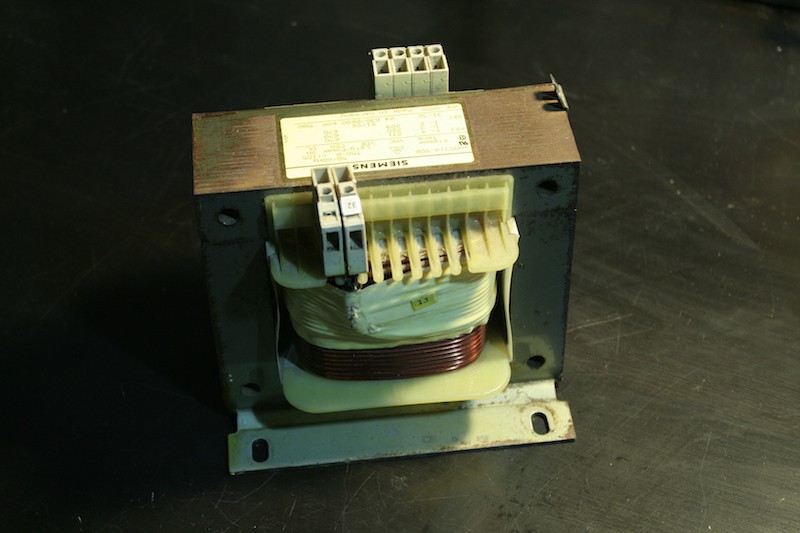
Further thoughts
Even though it looks cool with the blue LEDs and gets hot quick, this is still very much unfinished. I.e. the polycarbonate cover for the LED circuit is still missing. The LEDs are too bright, too. I think I'll try a higher value than 1 kΩ for the current limiting resistor next time. The wiring with the cable lugs worked better than expected. Prepping all the wires is tedious though, I guess I need to have them made professionally. I noticed I need to find a better solution for the foldback clamps. The fuses also need to be tested, soon, both their reliability in deflecting the apocalypse and their ability to operate reliable close to the apocalypse. But well, so far that looks really, really good. And look, I can now find a new purpose for that 24 V~ 500W transformer that used to power my old MK2B heated bed:
![]()
-
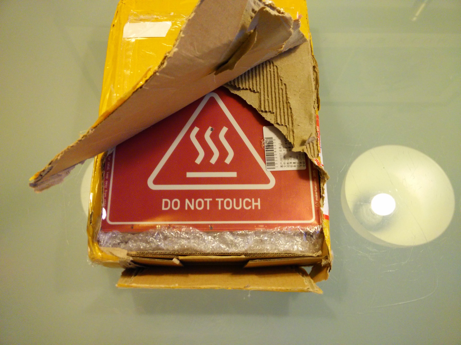
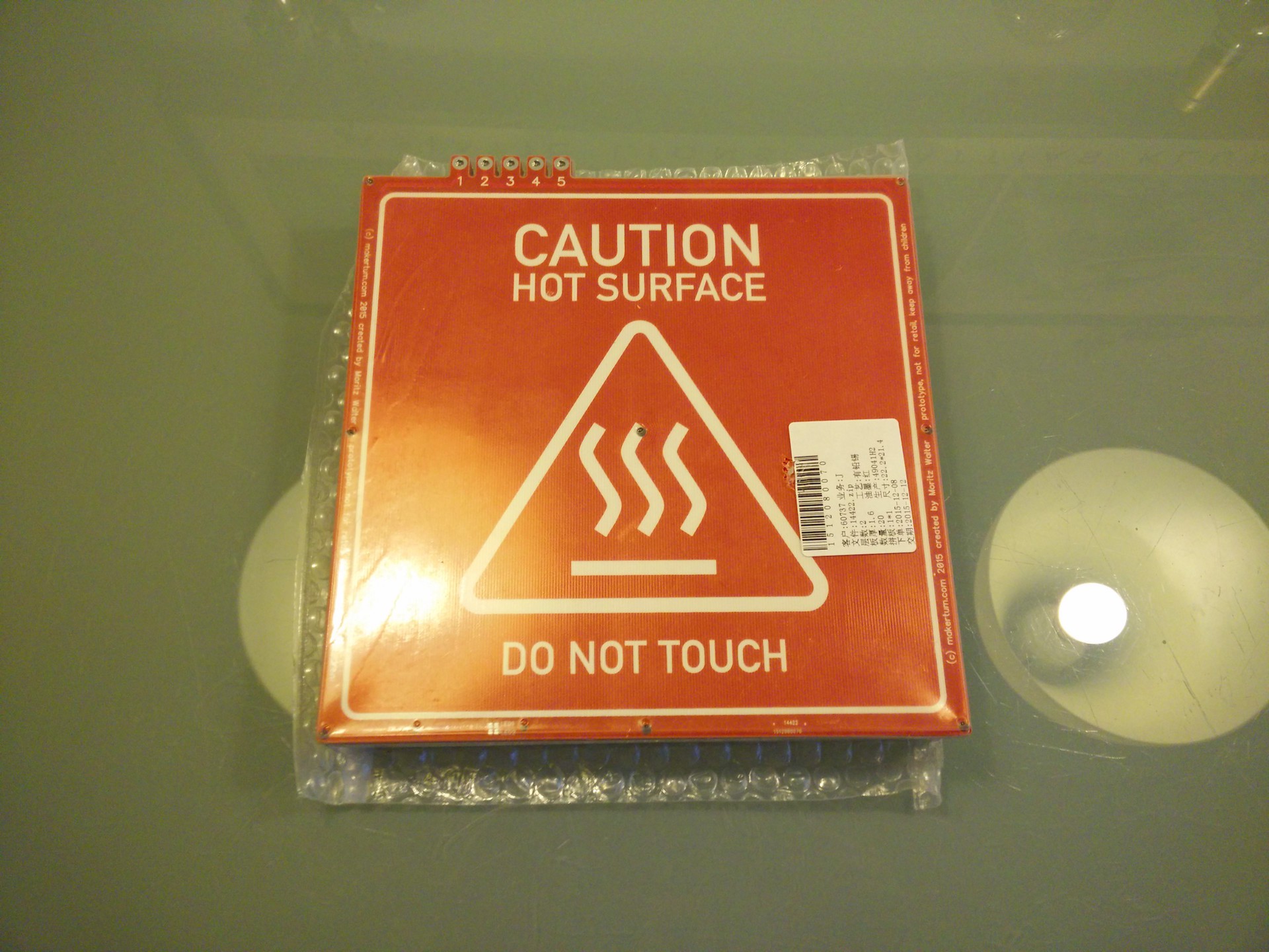
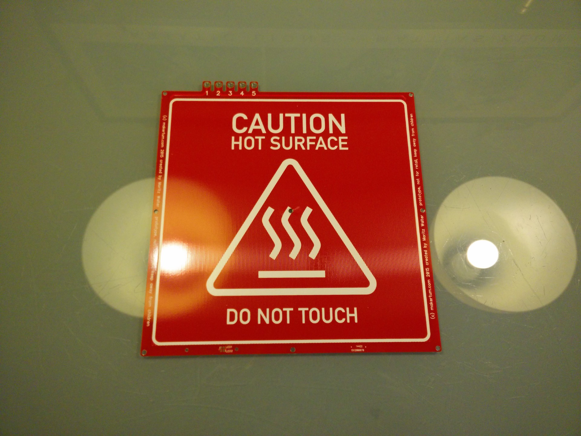
First batch arrived
12/22/2015 at 13:34 • 0 commentsGood news everyone, the first batch of 20 heated beds arrived today. They do look fantastic and are expected to work as they should. So first, enjoy the pictures, and then I'll also look into the electrical properties of the boards and compare the actual to the design specs.
Pictures
![]()
![]()
![]()
![]()
![]()
![]()
![]()
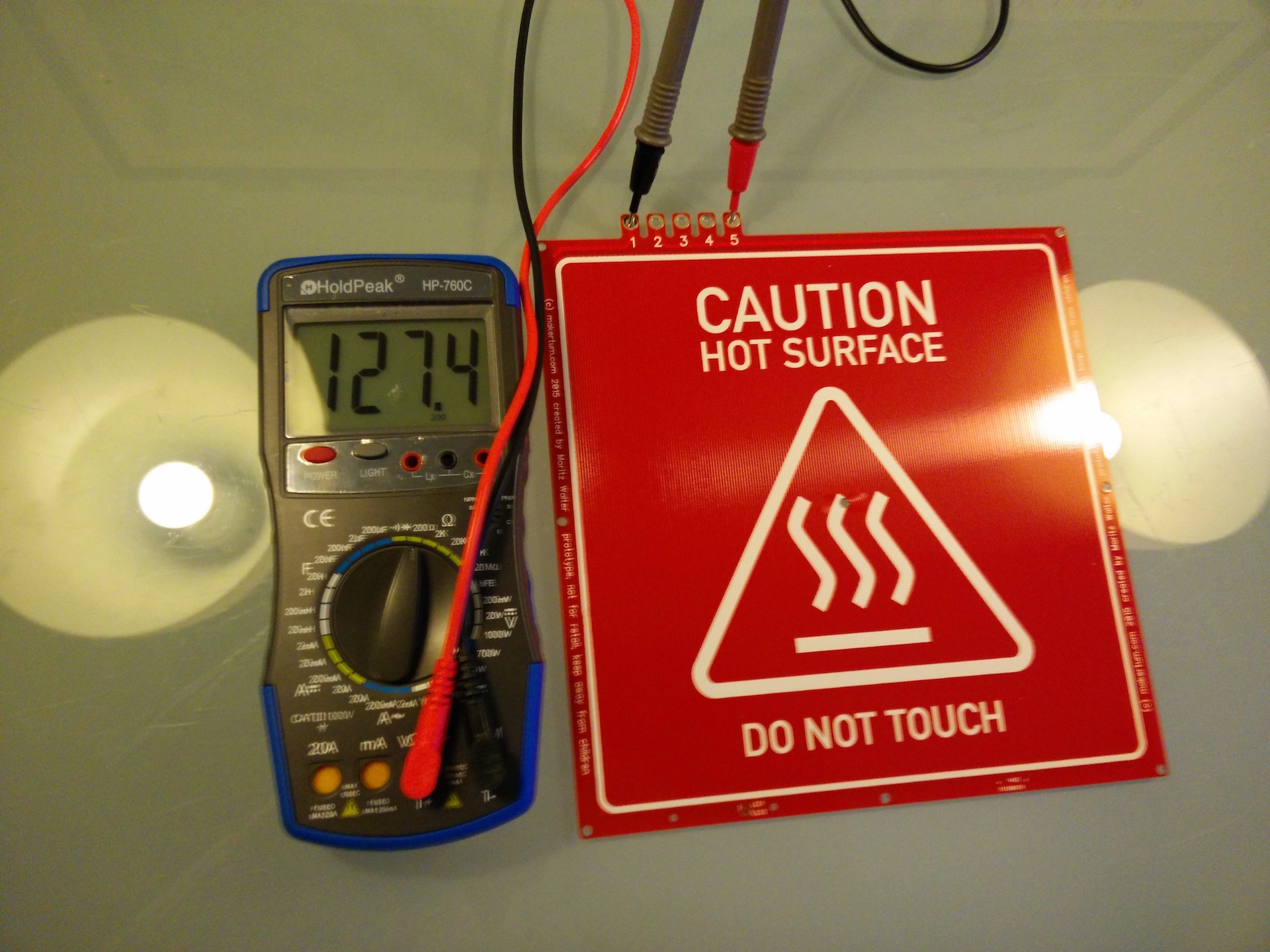
Actual properties
As you can see below, the full trace has about 127 Ω, which is about 20 Ω (or 20 %) more than my math suggested. That sounds (and is) much, but only means that they'll output 20% less power than expected, which is still 400 W.
The difference probably comes from a combination of several factors in the manufacturing of the PCBs. First, the copper thickness, for which I assumed the 34 µm a 1 oz copper clad suggests. Then the copper conductivity, which can also vary widely, especially if you have no idea about what value to start with (I assumed 0,017 Ω*mm/m), and eventually, the geometrical manufacturing accuracy, since the "precisely" 0,37mm wide and about 80m long heater trace is an extreme case that pushes the specifications a manufacturer can guarantee for to the limits.
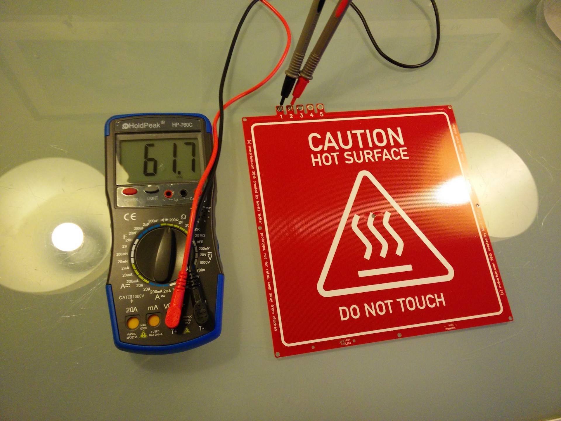
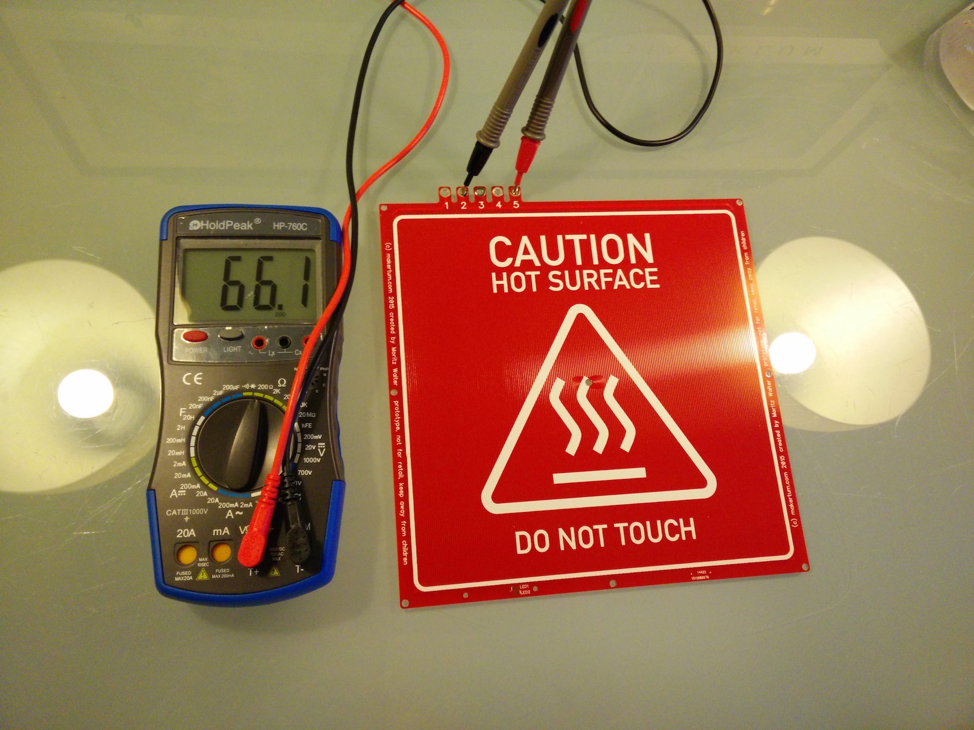
![]()
Since our board has two sides, we can at least get a clue of what magnitude the actual tolerances are in, and where I just guessed wrong. Below you can see how the resistance of the top layer differs from the resistance of the bottom layer by about 7% and we can actually make a good guess what's causing this. Since the offset tolerances are insanely low, it's impossible that the geometrical differences between the top and the bottom layer are 7%. Assuming that top and bottom side use somewhat the same copper, it must be due to tolerances in the copper thickness. Mind that this is just one sample, so all it tells us is that the copper thickness can be off by 7%.
![]()
![]()
Next steps
So, even if the boards are a little out of spec, 400 W is still a value that will work perfectly for 3D printing and will significantly improve heatup times for most. That means, that I can start testing the boards and see if they survive the high temperatures. I will probably setup a safe testing environment where I can let the board run continuously for 30 days or more simulating heatup and cooldown cycles, regular printing temperatures of 110 °C as well as extreme scenarios like long term stress tests at 130 °C.
I'll also soon place some orders on further parts for the boards, like LEDs, fuses and polycarbonate sheets for milling the LED covers. So if the testing is successful and no bad things happen, this first batch will go out to betatesters as self assembly kits with all the necessary components. So if you're interested in trying this out, just send me a PM or post a comment.
-
GitHub repository
12/11/2015 at 14:14 • 0 comments -
Manufacturing has started
12/06/2015 at 18:32 • 0 commentsI've just sent the boards to dirtypcbs.com. Until they arrive, enjoy this renderings (I really hope those thick silkscreens work out..).
![]()
![]()
-
Manufacturing considerations; safety
12/06/2015 at 16:20 • 1 commentRouting dimension tolerance
Preparing the manufacturing of the boards, I've noticed that most manufacturers specify a relative trace impedance tolerance of about +-15%. That's a lot, but it's also mostly due to the the absolute routing dimension tolerance of up to 4mil. Since it's mostly due to an absolute error, the effect of it can be minimized by increasing the trace width. In case of the PCB heater, increasing the trace width decreases the trace resistance, which must be compensated by proportionaly increasing the trace length.
Because a double sided heater PCB has additional benefits in tackling thermal deformations within the PCB, I chose to redesign the PCB with double trace width and double trace length, which runs over both sides of the PCB. I could not decrease the gaps between the traces any further, since they're already pretty tight pitched.
Dual voltage
Thinking back and forth if it makes sense to have the board accommodate 230 V and 110 V AC for use in EU and US I came to the conclusion, that there are definitely many more 110 V 3D printers out there than 230 V, so omitting 110 V is not quite an option. However, supporting two voltages on one board blows up the number of necessary connectors from 2 to 5. Those connectors are basically free in the production, but in the installation it means also 3 additional cable lugs, copper screws/nuts and a bridging wire. However, the 5 connector solution also allows the thermal fuse to be omitted in experimental configurations. The pads and connectors of the thermal fuse can then be used to wire the thermistor. It also might be easier to find some beta testers for the board with dual voltage support, so I'll just make the first batch dual voltage and see how it goes from there.
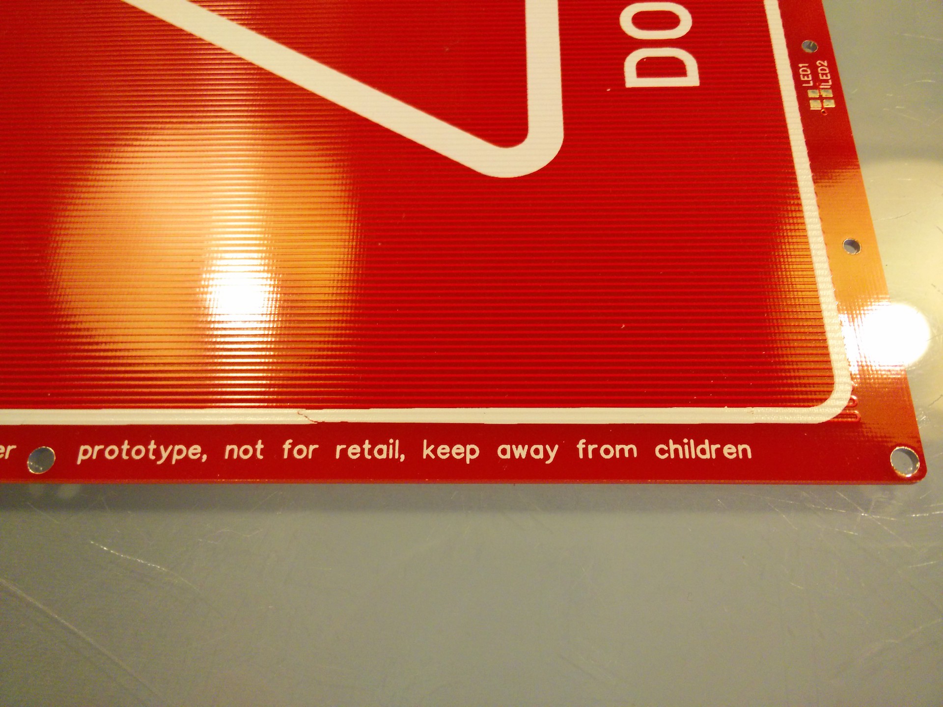
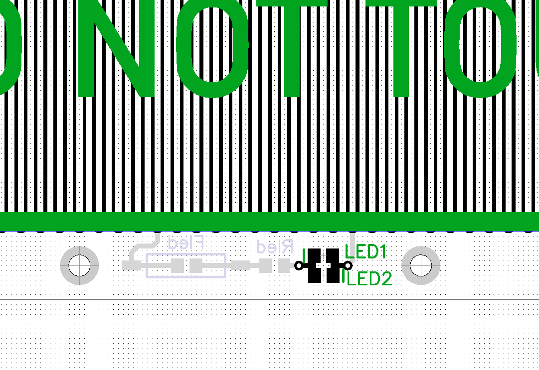
LED fuse and plastic cover mount
The led has now a fuse mounted to the back side and two mounting holes for a transparent protective plastic cover to be mounted over the components.
![]()
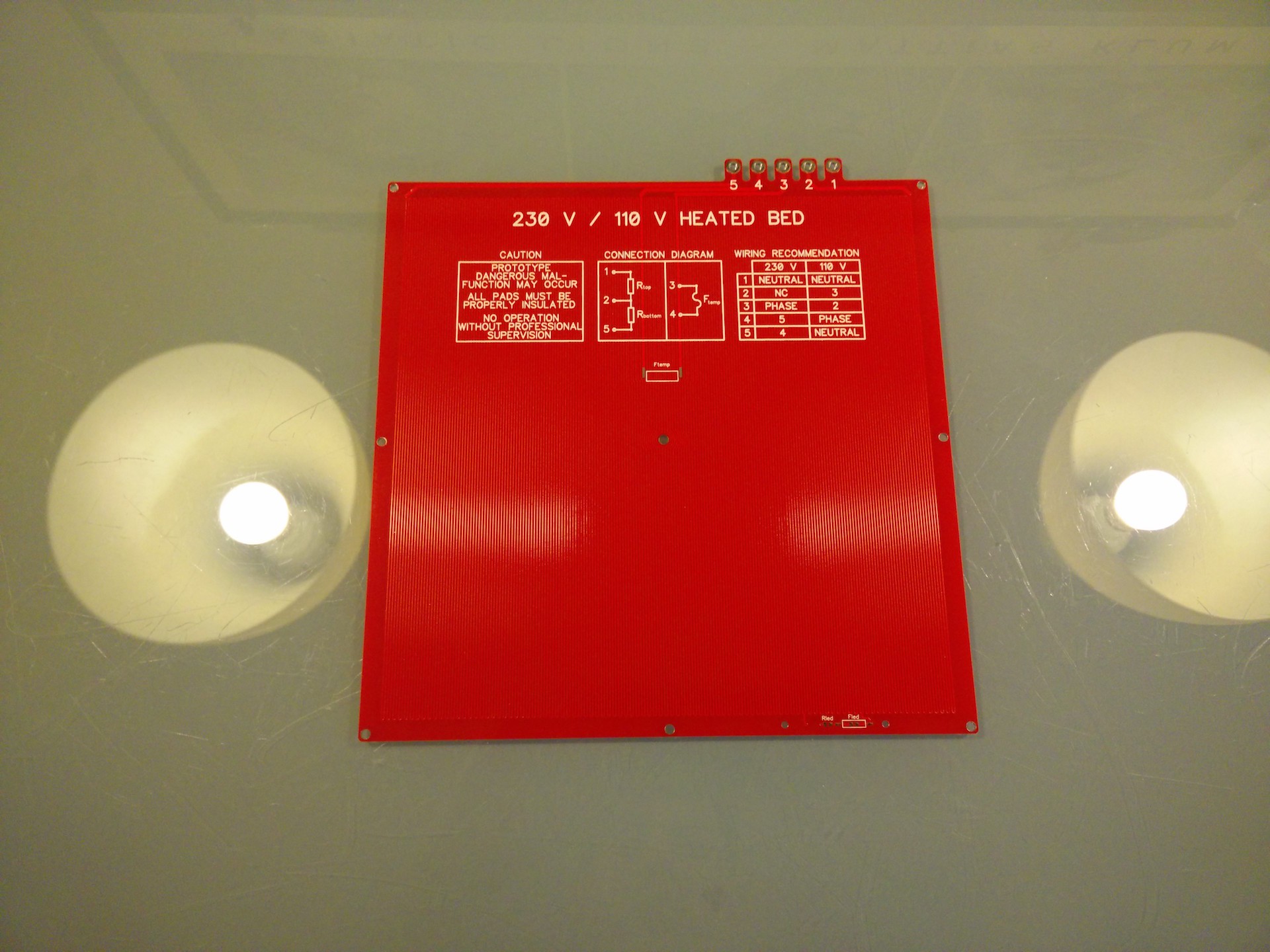
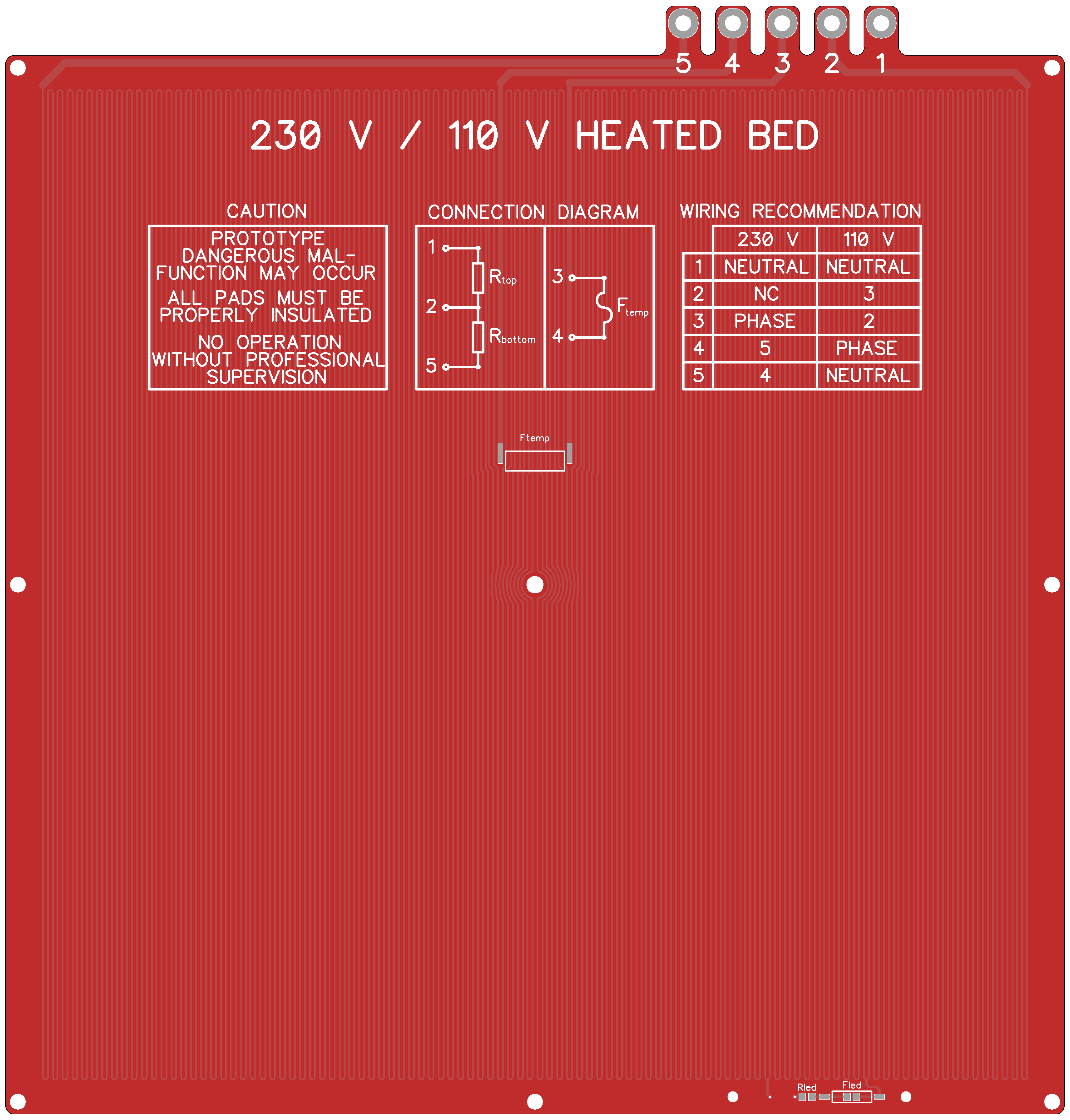
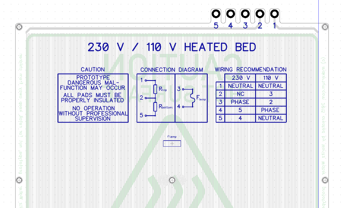
Silk screen documentation
The best documentation is the documentation you have at hand, so I included the connection diagrams and wiring hints on the back side.
![]()
Three point leveling
I know some of you prefer the option of using a simple three point leveling, so I moved the LED circuit a bit to the side and added a "third" mounting hole to the front, left and right side of the board.
![]()
-
Safety considerations
12/05/2015 at 17:12 • 0 commentsAs mentioned, there are some safety concerns in heated beds no matter what voltage they are running on. I like the pragmatism of many RepRap builds out there, and I'm defenitely not safety fanatic, but I have the feeling that in terms of safety there is still room for improvement. The way some DIY printers are thrown together is actually pretty scary and we all know that the MTBF on these can be pretty low.
Overheating protection
With the intent to make this heated bed as safe as possible, what can we do? Adding a thermistor is a good idea, but what if it fails? What if the logic reading the thermistor fails. It might be a good idea to add another protection loop.
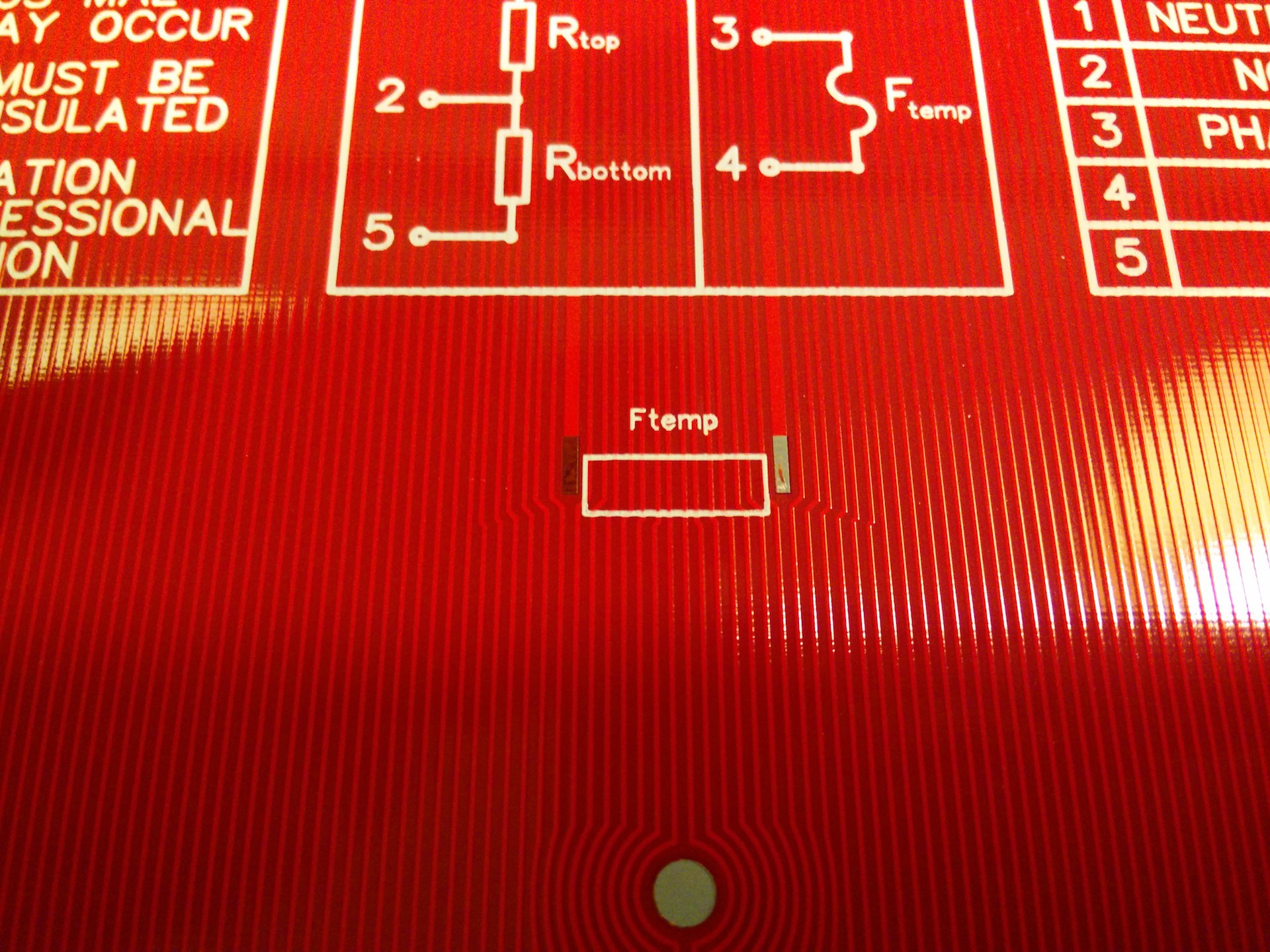
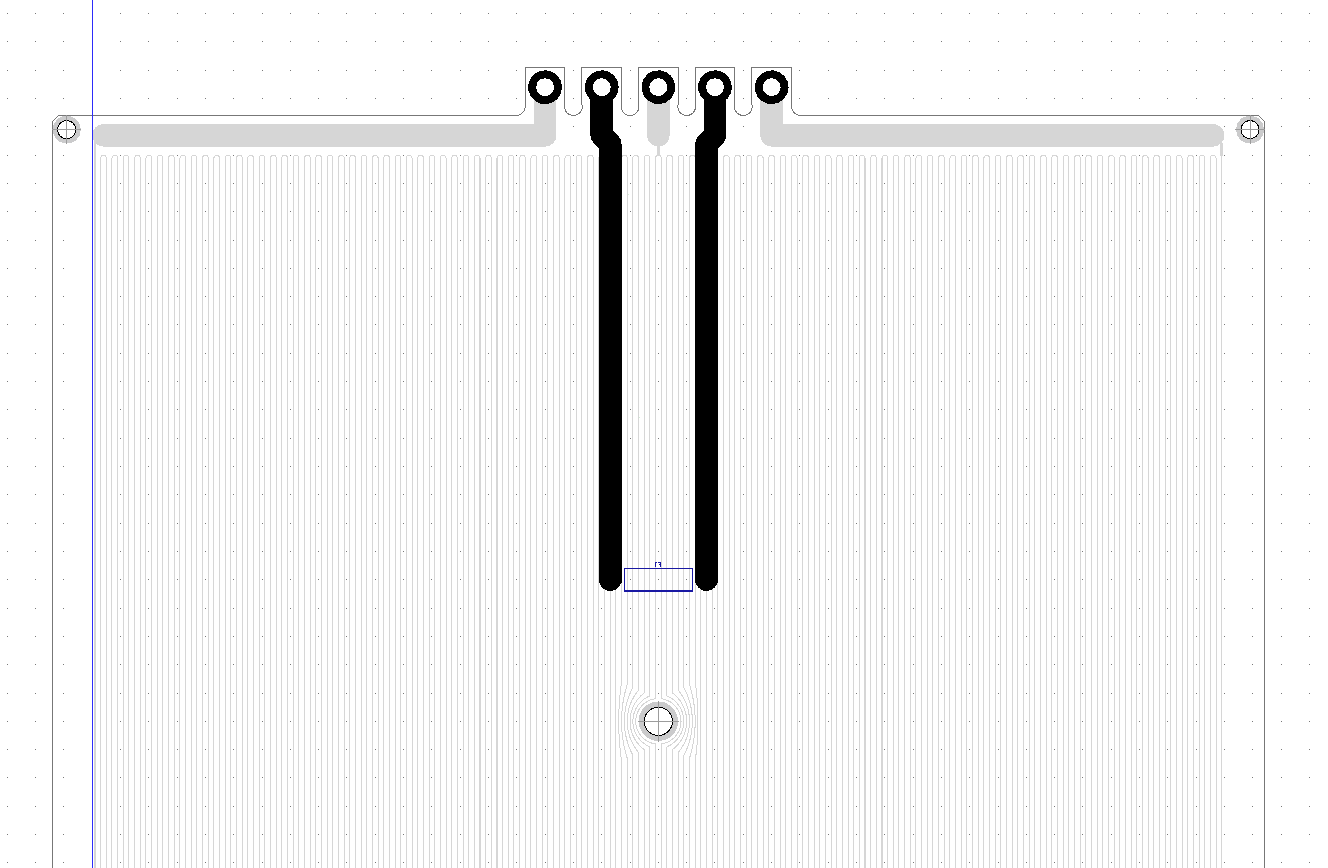
Below you can see the heated bed with two additional terminals, which a routed to a thermal fuse on the bottom side, close to the center of the heated bed. This way, you can still decide if and how you want to employ a thermal fuse.
The thermal fuse could also be implemented differently, i.e. just tapping it into the center of the heating trace, but then there would be two footprints required, one for 230 V~ and one for 110 V~ operation.
![]()
![]()
LED protection
Another unsafe feature of the PCB in the current state is the vulnerability of the LED to faults in the section of the heater trace it feeds from. A open connection (like when the trace burns through) in this section would cause an increase in the voltage drop over the LED and its current limiting resistor. The current would also increase from 10 to 200 mA, which would probably blow both the LEDs plus the resistor. The only solution is employing a fuse, which just not so elegant as you can see in the picture below. I am not sure if this is actually necessary, because if there would actually be an open connection in the heater trace, the increased voltage and current will make the 0805 resistor pop right off, opening the circuit.
![]()
Overcurrent protection
Overcurrent protection is simple: Just add a fuse and feel safe. However, in the current design it's hard to employ a fuse that works for both 230 V~ and 110 V~. Since this was already a problem with the thermal fuse, I'm considering to just make two different designs, one for 230 V~ and one for 110 V~. Also, through hole components (like most fuse holders) are not allowed, since the PCB must remain flush on one side. Since there is no necessity to have the current fuse onboard, I chose to leave it to a cable fuse holder.
-
Design Specs RFC
12/05/2015 at 11:59 • 4 commentsDesign specs
Note: these specs have been updated to reflect the current status of the project, while the images in this log are a bit out of date in terms of trace length and other details.
Power consumption 500 W (230 V~) or 460 (110 V~) Operation Voltage 230 V~ (110 V~ over a center tap) Resistance: 106 Ω Trace length 400 x 200 mm = 80,000 mm Copper thickness (on PCB) 1oz aka 1.37 mil aka 35 µm Trace width 0.37 mm It's unclear how the PCBs will actually perform once they're manufacured, but if they're not too much off those parameters, they'll probably work. [Edit: It's not so unclear anymore, see below]
Actual specs (1st batch)
Note: these are the specs of the actually manufactured boards, they differ from the design specs due to manufacturing tolerances and my personal learning curve in this project.
Power consumption 420 W (230 V~) or 380 (110 V~) Operation Voltage 230 V~ (110 V~ over a center tap) Resistance: 127 Ω Trace length 400 x 200 mm = 80,000 mm Copper thickness (on PCB) probably a bit less than 35 µm Trace width round about 0.37 mm Design/Layout
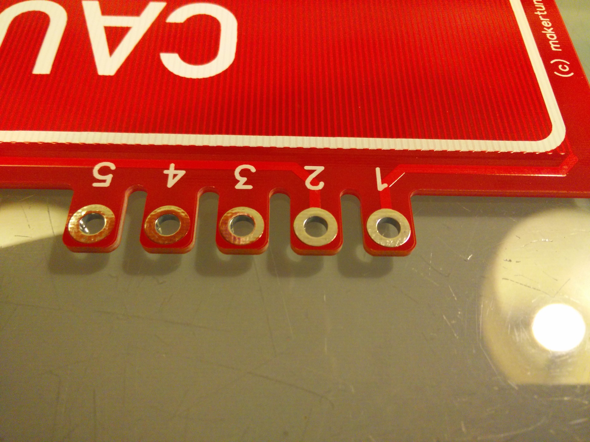
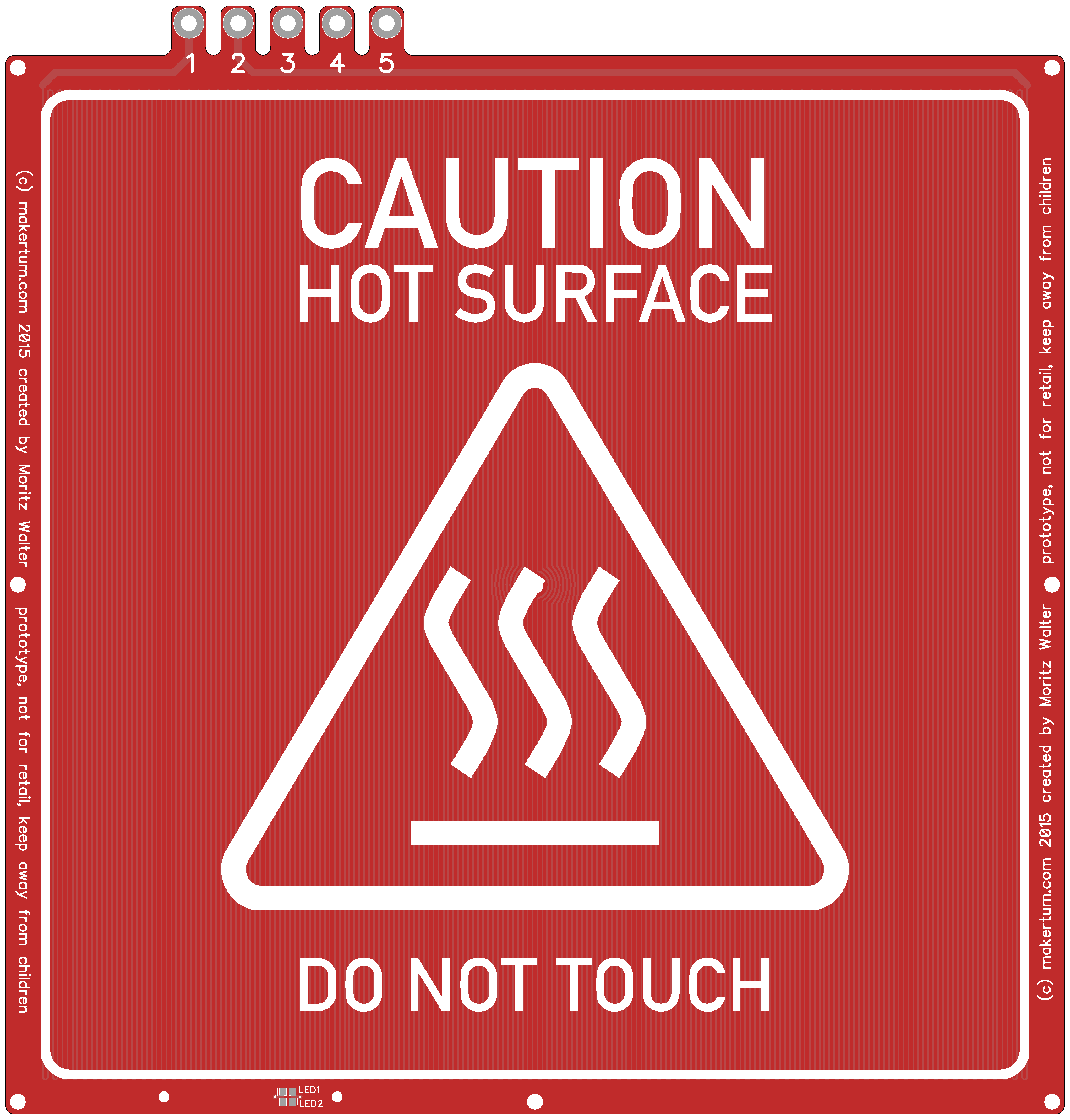
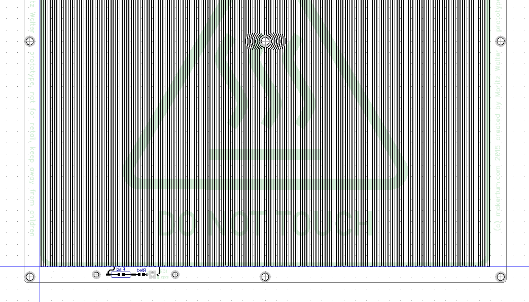
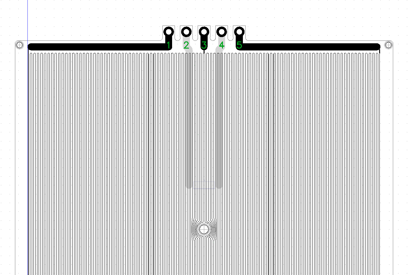
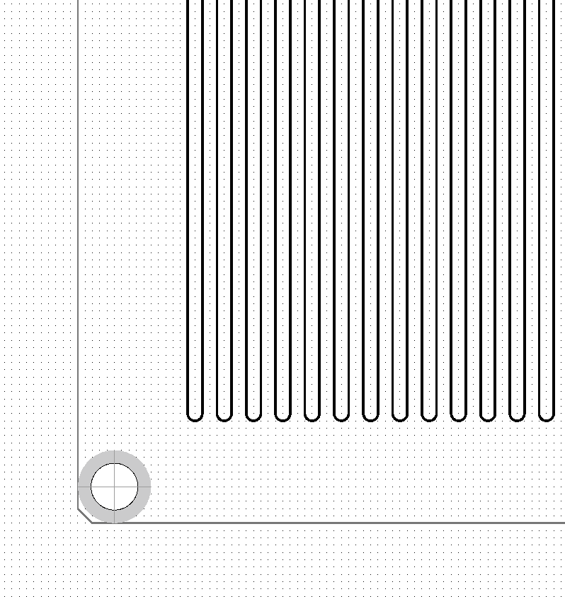
Below you can see the single sided layout of the board. The connectors are meant to be interfacing with M3 cable lugs. I've offset them to be outside of the board, so that shrinking tubes can be used to insolate the connectors once the cable lugs have been attached. The size of the bed is 214x214mm (excluding the terminals) and the center-to-center distance of the mounting holes is 209 mm, so it's compatible with all the MK2 heated bed mounts out there.
![]()
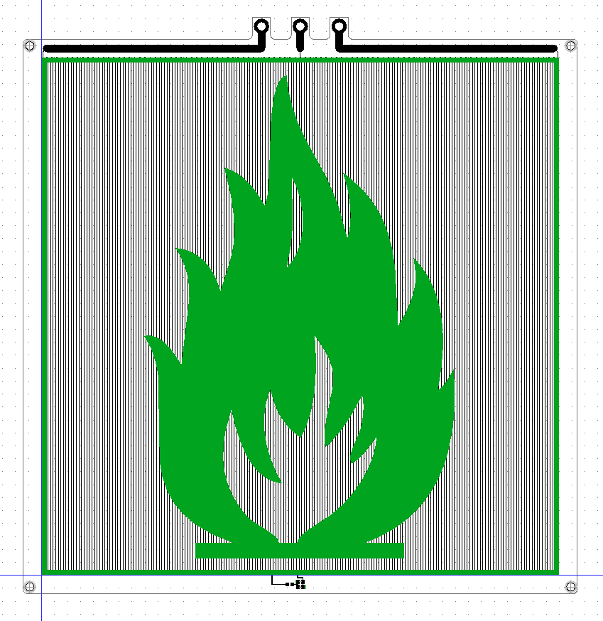
The routing is super simple, just a looooong trance.
![]()
The board can be used with 110 V~ by applying the phase to the outer two terminals and neutral to the center terminal. The heat power output for 110 V~ will be a bit lower, about 460 W.
![]()
Power Indicator LED
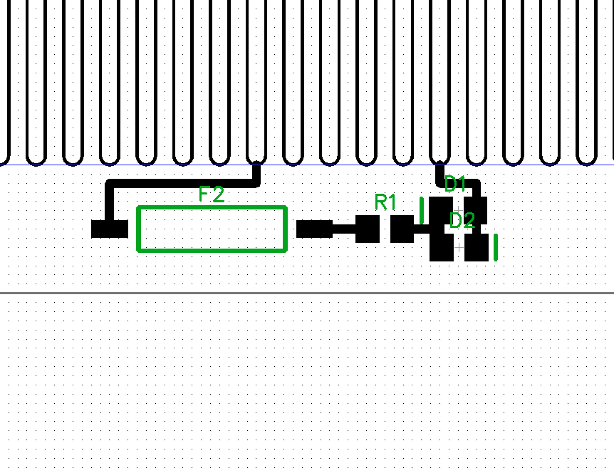
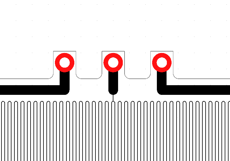
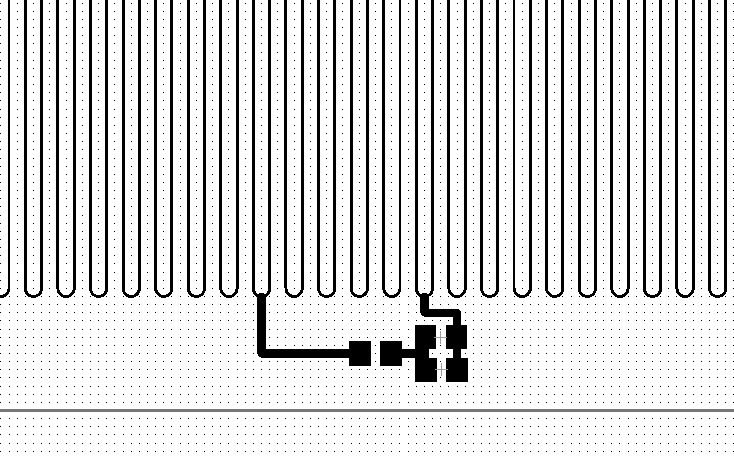
Last but not least, I'm thinking of adding a power indicator LED. It taps into the long trace and takes 10 of the 201 vertical traces, which results in about 12 V voltage differential. I used two 0805 LEDs (one LED for each half wave) to prevent the backward voltage for the non conducting LED blowing it, the third footprint is for a 1kΩ 0805 resistor.
Since these expose hazardous voltages of up to 115 V in normal operation, they have to be sealed using some heat resistant, transparent epoxy or kapton. I'm still not sure if it's worth it to expose the mains traces for the sake of having an indicator light. Since the LED is attached close to the center tap, at least 110 V~ users will not have hazardous voltages on those pads during normal operations.
![]()
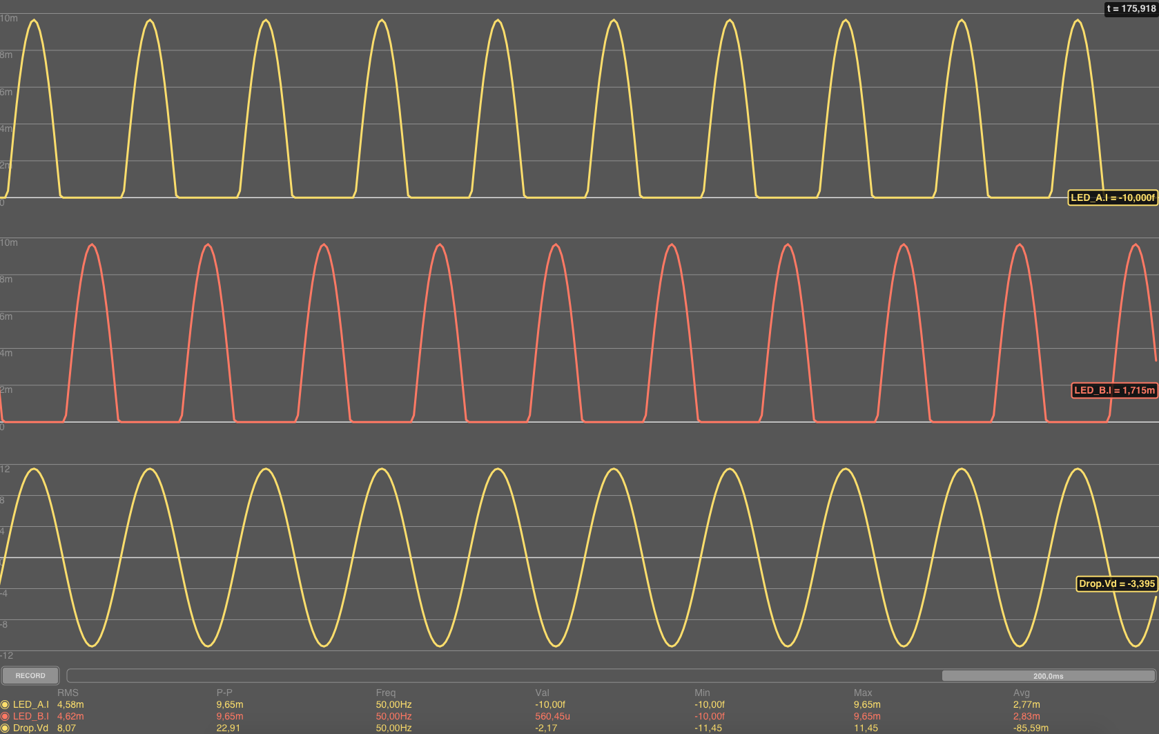
Tapping into the heater trace has the advantage, that the led circuit is not exposed to 230V, thus the current limiting resistor does not have to dissipate so much power. I've also simulated the voltage drop and current for this setup:
![]()
The disadvantage is, that if the heater trace burns through and leaves an open connection point in the section where the LEDs are tapped, the full mains voltage is applied to the LEDs and resistor. The current would still be limited to about 200 mA by the rest of the traces and the resistor, but if the 0805 resistor cannot handle the increased drop of about 210 V, the resistor will burn through and pop right of, so actually, an additional SMD fuse will be required.
RFC
I'm looking forward to get some comments on this, since there are probably some specialists here who can contribute some good ideas (or concerns) to this.
110 / 230 V~ PCB Heated Bed
Meet the Makertum MK1, a 500W PCB heated bed that runs from mains voltage