ajlitt
-
WiFi broken? Update your driver!
05/11/2017 at 02:58 • 1 commentRecently Raspbian switched to a 4.9 kernel from the 4.4 based kernel that's been the norm for a while. This breaks the esp8089 driver. If your esp8089 module no longer loads following an apt-get upgrade, this is likely the problem.
Thankfully den4ix on github issued a pull request this morning that updates the APIs for 4.9. The fix is in the latest Debian DKMS package released this afternoon.
To update the driver, download the new esp8089 DKMS package from github and install on top of the old package:
wget https://github.com/al177/esp8089/releases/download/1.9.20170510/esp8089-dkms_1.9.20170510_all.deb
sudo dpkg -i esp8089-dkms_1.9.20170510_all.deb
Reboot after the package is installed to reload the esp8089 driver.
-
It's been fun
02/28/2017 at 15:27 • 3 commentsNow that the Raspberry Pi Zero W is out, there's not much reason to use a WiFi Pants board. The Zero W is more compact, cheaper, and has out-of-the-box Raspbian support for WiFi. Also Bluetooth.
If you need battery power for your Pi Zero project, please consider the amazing LiFePO4wered/Pi .
Thanks to everyone who supported this project!
-
Licenses, longevity, lights
10/23/2016 at 04:01 • 0 commentsIt's been a while, huh?
Much has happened over the last few weeks. The biggest news is that Espressif has agreed to allow their ESP8089 driver to be licensed under GPLv2 and the associated binary blob firmware to be put under the Apache license. Now the driver powering this project as well as many tablet devices can be submitted for inclusion in the Linux kernel. A few embedded Linux enthusiasts have stepped up to clean up the code and push it through the kernel patch submission process. Thanks to Jeroen@Espressif for getting the approvals, and the free-electrons folks, jwrdegeode, noahwilliamson, and icenowy for their ongoing work in making the driver kernel-ready.
About two weeks ago I sold the last finished WiFi Pants kit in my inventory. I'm also running out of my long lead time components: PCBs, ESP modules, and the long stack through headers. I will be doing another run of kits which should be in stock in a couple of weeks, but after those are gone it's going to take a couple of months to build any more.
Finally, I was lucky enough to participate in the first Hackaday TV hangout and talk for a few minutes about my project with Sophie Kravitz and Limor Fried and hear about some really neat Pi hacks. But while excitedly rambling on about my WiFi Pants project, I forgot to point out the demo I put together to show off the WiFi pants board's power supply. You can see it on the bench behind me in the video blinking away.
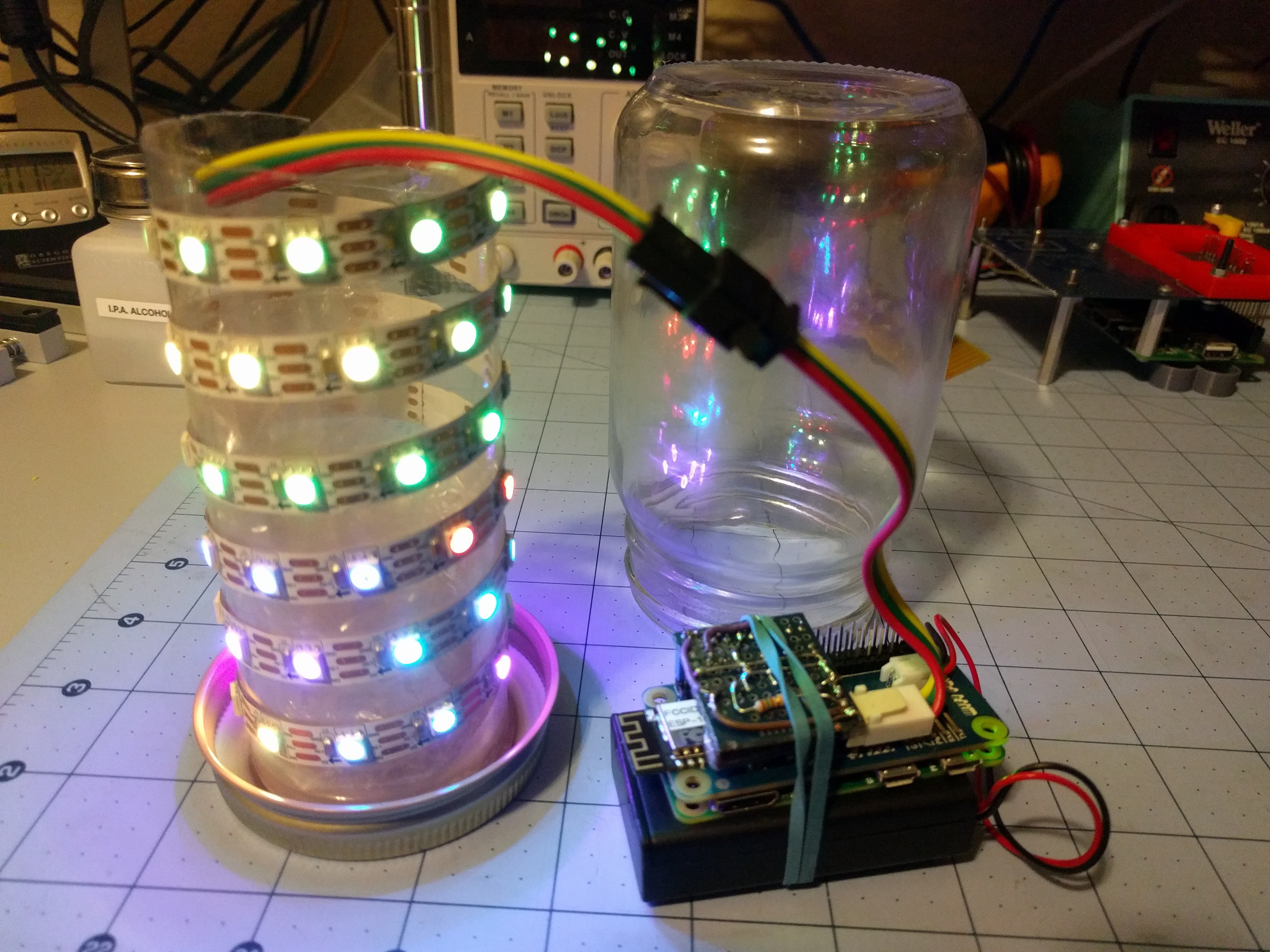
Behold, the Access Point Sniffer Thing With LEDs in a Jelly Jar That I Haven't Considered Naming Until Right This Moment, or APSTWLJJTHCNURTM for short:
![]()
![]()
It's a WS2812 LED strip in a jar that changes patterns depending on the number and strength of WiFi accesss points in the area. It uses a 60 LED WS2812 strip, WiFi Pants, a Pi Zero, 3 AAA NiMh batteries, a jam jar, a plastic tube from the packaging for a USB charger, plenty of clear packing tape, a few dabs of hot glue, and a WS2812 level shifter board made with junk box bits. Software is in Python using the rpi_ws281x library for talking to the LEDs and iw_parse to simplify the AP scan.
Every second or so the Pi does a scan of the available networks. The networks are sorted by the signal strength and assigned an LED for each 4dB of signal strength. Each access point gets its own color by hashing the last 3 octets (the non-OUI portion) into hue and saturation. You can see at the bottom in the gif above that the LEDs towards the bottom of the jar are more uniformly colored and don't change much, while the APs that have weaker signals dance around with a larger variety of colors towards the top as they come in and out of range.
Total time spent on this was about 5 hours. I figured that the string at full brightness plus the Pi and ESP8266 would push near the 2A limit of the boost converter, making it a good demo. However the LEDs at full power saturated my webcam to the point that the jar looked like it was filled with burning magnesium, so it's limited to 1/8 brightness. That's probably for the best, as the AAA batteries droop too much at full LED power to keep up with the 4A or so the converter pulls at its limits.
Thanks HaD, Adafruit, Limor, Sophie, and all the other hackers for a fun hour of sharing projects!
-
Need Pants?
06/07/2016 at 19:34 • 3 commentsI have a few WiFi Pants boards listed on Tindie. Have at 'em
-
Driver update
05/23/2016 at 15:52 • 3 commentsLast night I checked in a change to the esp8089 driver that automates toggling the reset (CH_PD) on the ESP by GPIO. With this change ESP hacks based on the instructions here will automatically come up during boot without any scripting or external reset circuits. This also issues a reset on module unload which is needed so that the ESP is detected after a soft reboot (reboot on the command line, etc) and keeps the module from OOPSing when reloaded without a previous reset.
The project instructions have been updated to reflect this change. If you previously added sysfs GPIO or module unload commands in your init scripts for the ESP (rc.local and otherwise) you'll need to take them out. The driver defaults to GPIO0 (ID_SD like the WiFI Pants uses), but you can pass the esp_reset_gpio module parameter with the GPIO number your board uses. This should be platform agnostic as long as the target has a kernel GPIO driver.
The driver still isn't ideal since it must always be rebuilt every time the Pi kernel changes. On other Debian based systems this could be handled with dkms, but the Pi Foundation's non package based kernel scheme makes it difficult. Of course I have a build process to help with this, but that's dependent on a network connection and gets unpleasant on the Zero. One solution would be to build the driver against each Pi kernel release and index it by the kernel's commit hash (like rpi-source). If anyone has ideas for a cheap (or free) binary release hosting service I'd be open to setting up an automated build server.
As for the WiFi Pants... I still have the first batch sitting on my desk. I wanted to get this driver change in to simplify initial setup, and still have some documentation to do. Keep an eye on the github wiki and on this project for details.
-
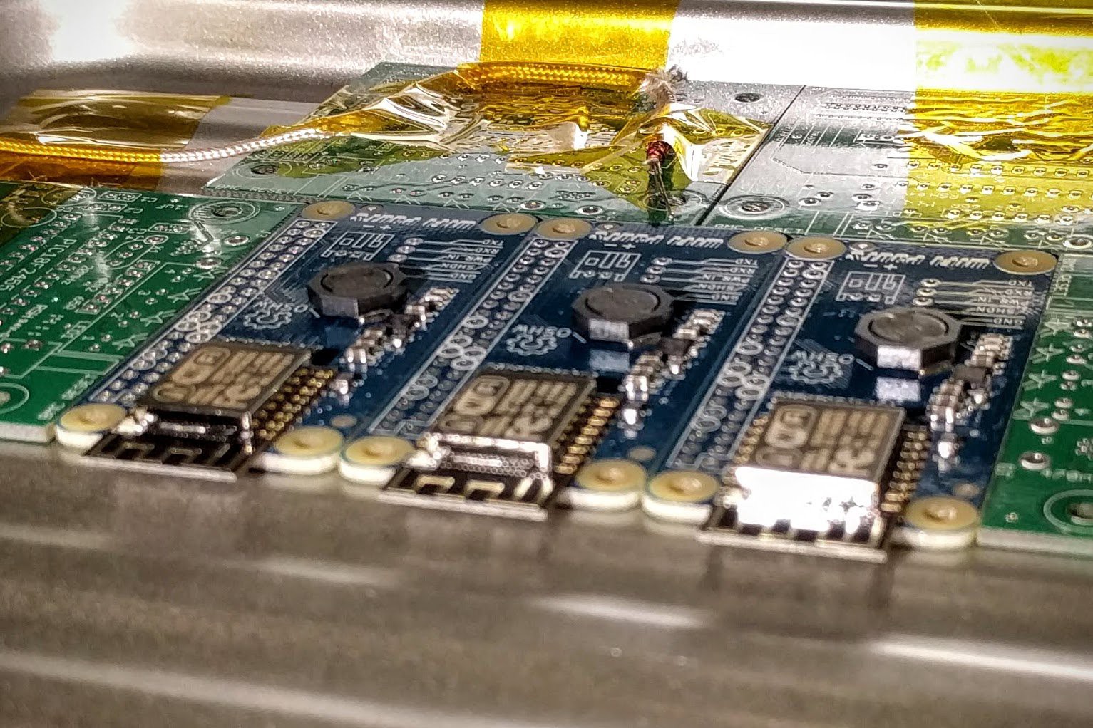
Production starts!
04/14/2016 at 06:04 • 4 comments![]()
![]()
![]()
Repeat 9x.
-
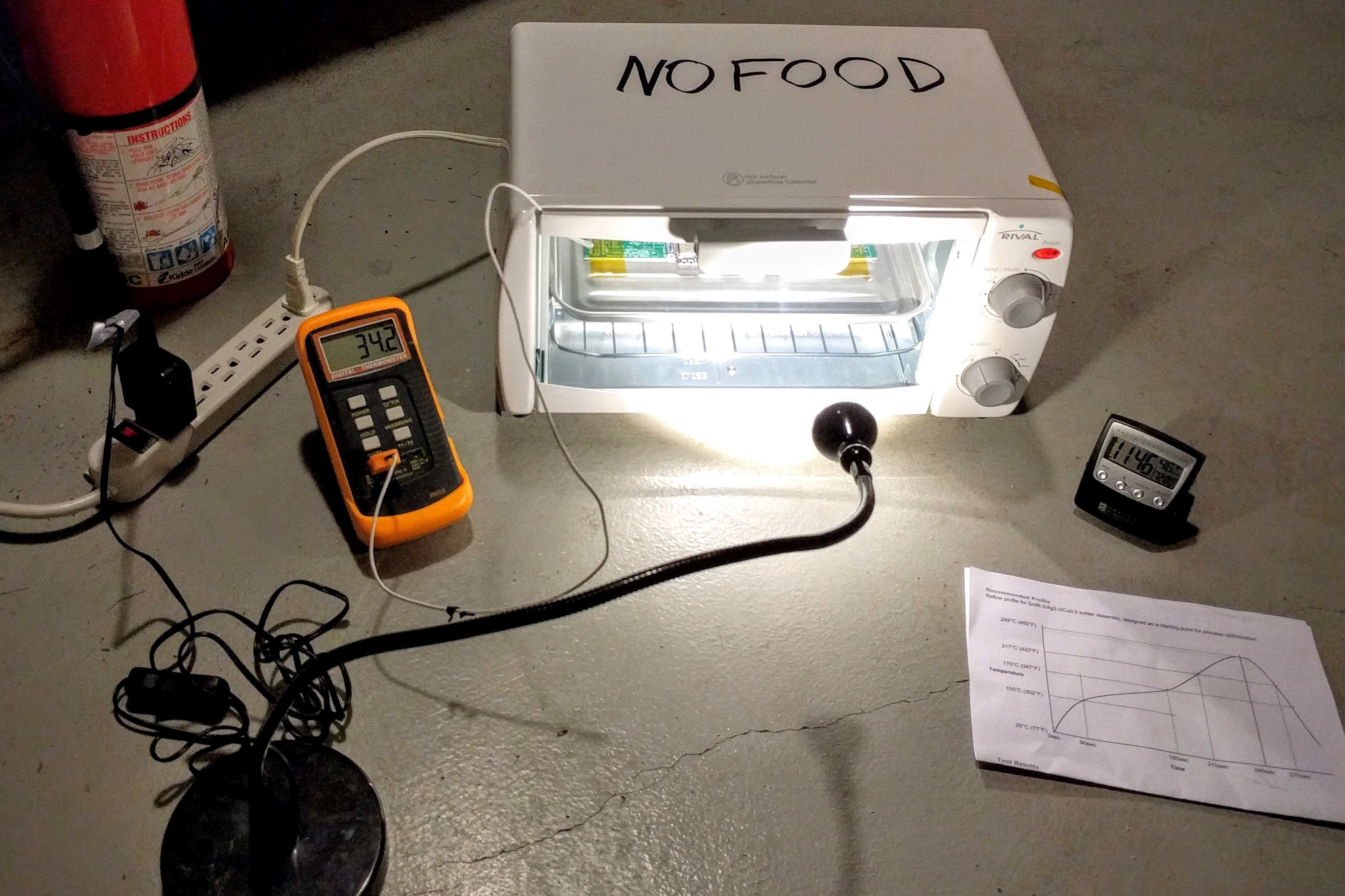
Testing the tester
04/10/2016 at 16:59 • 0 comments![]()
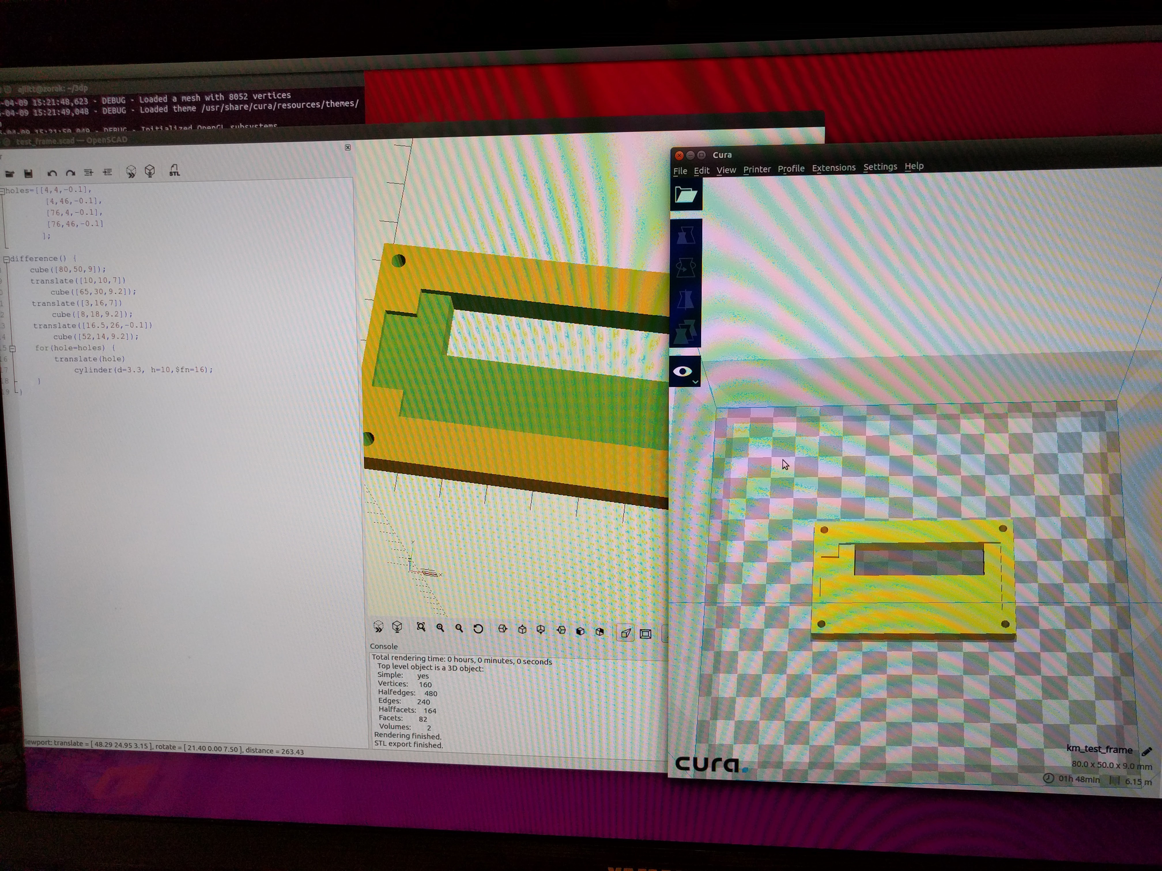
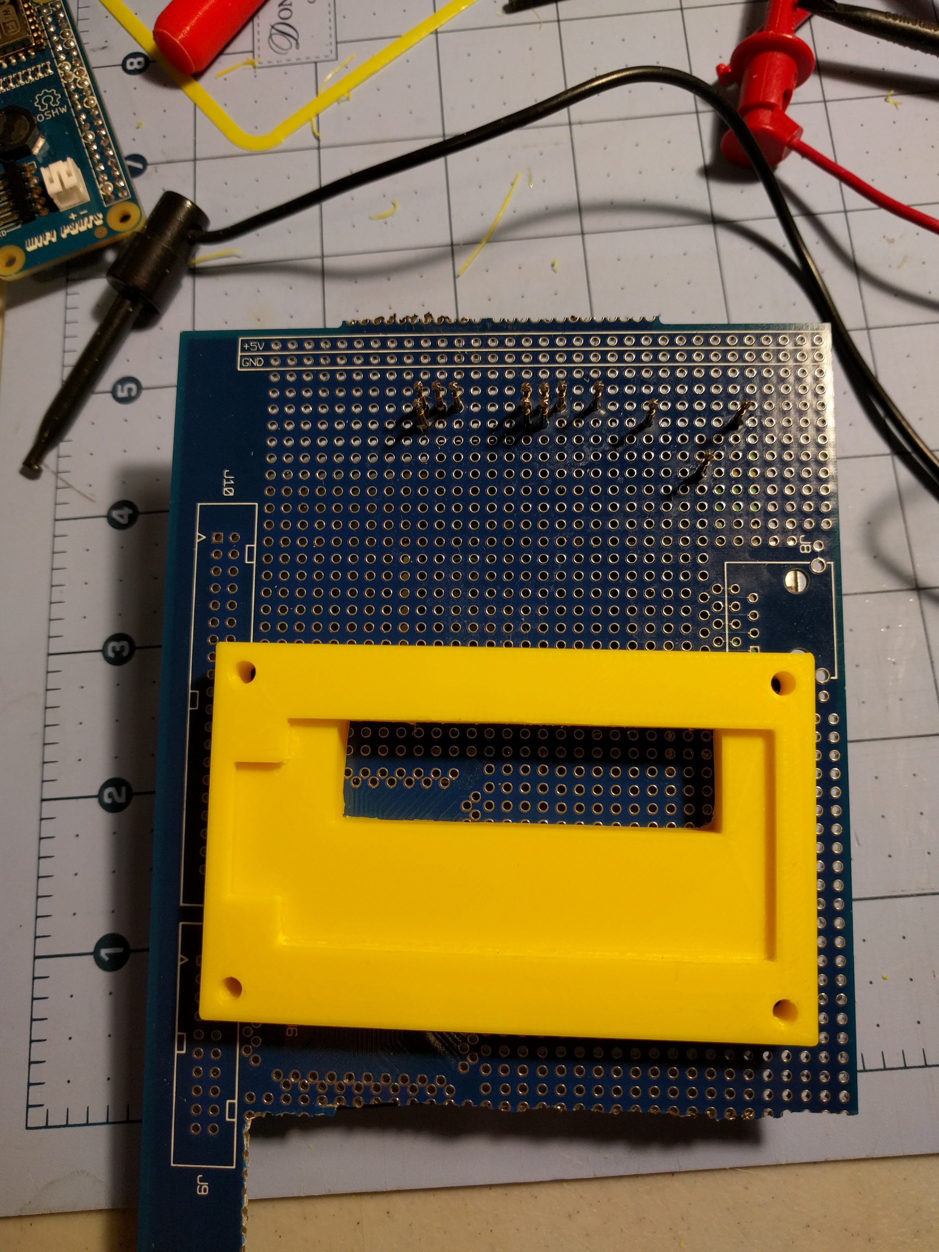
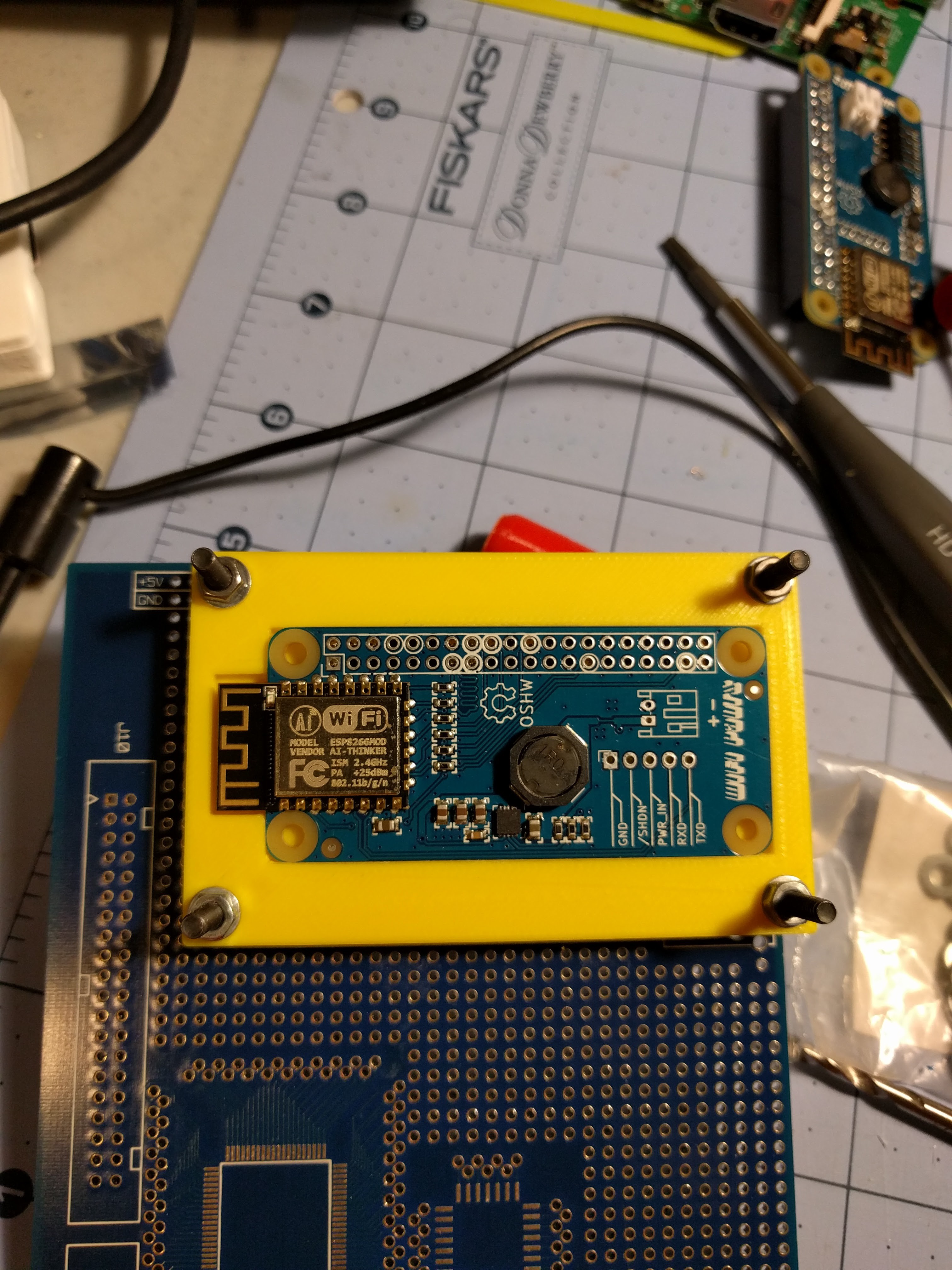
The test jig / bed of nails is coming along nicely. I OpenSCAD'd a mount and retention clips for the DUT, and with some filing and drilling out the PCB the DUT and pogo pins line up reliably and the DUT stays put. A choco-block terminal strip connects to the PSU and lets me clamp to the disposable DMM probes. The DMMs need test leads with an odd mini banana plug, so rather than trying to make custom cables I just clamp the probes in the terminals. They're used only for voltage measurement so this is fine. Some more drilling, standoffs, and a power jack for separate power to the Pi A+ round out the fixture.
The output load is simply 8x 20 ohm power resistors in parallel for 0.4 ohms which gives 2A at 5V. They get a little toasty but don't seem to need active cooling.
A few bugs to fix in the next couple of days:
I'm seeing much higher voltage at the DUT for the input than at the fixture's DMM, so I'll try doing the Kelvin sense thing and run separate wires from the terminal block to the pogo pins for the input rail. Unfortunately there's only one pogo pin feeding the input to the DUT so I'm likely not going to see the actual voltage unless I redesign the PCB with a dedicated test pad for the input.
Also, the regulator is getting excessively hot, moreso than when I've tested it on proto builds. Most of the heatsinking is done with vias to the ground flood on the back, and my design for the mounting frame has a solid fill behind the DUT except for where the pogo pins are. I'm currently reprinting this with much more area under the part exposed and a little vent towards one side in attempts to let the switcher cool naturally.
The resistor load is working as planned, except it's just below the 2A point I want to test due to wire losses. So I might add another resistor in parallel to get closer to 2.25A which should make for sufficient testing margin. Easy enough since I've got a big bag of spares.
I drilled holes for three standoffs to support the fixture, but realized I located the pogo pins too close to an edge for one of the corners. Need to find a dowel or something to hot glue there.
I put a toggle switch from my junk bin on the board so I can shut off the Pi between DUTs, but the switch is flaky and cuts power at the slightest touch. It's shorted closed for now, but I'll eventually get a replacement.
And a final mistake that should have been obvious: I am seeing lower throughput on WiFi than on my proto builds. I don't see this when using the same DUT carefully held on a Pi's header, so it's likely the fancy recycled perfboard I'm using with the ground plane restricting the signal. That's ok as long as I'm seeing consistent behavior between units.
![]()
![]()
![]()
-
Knife sharpening
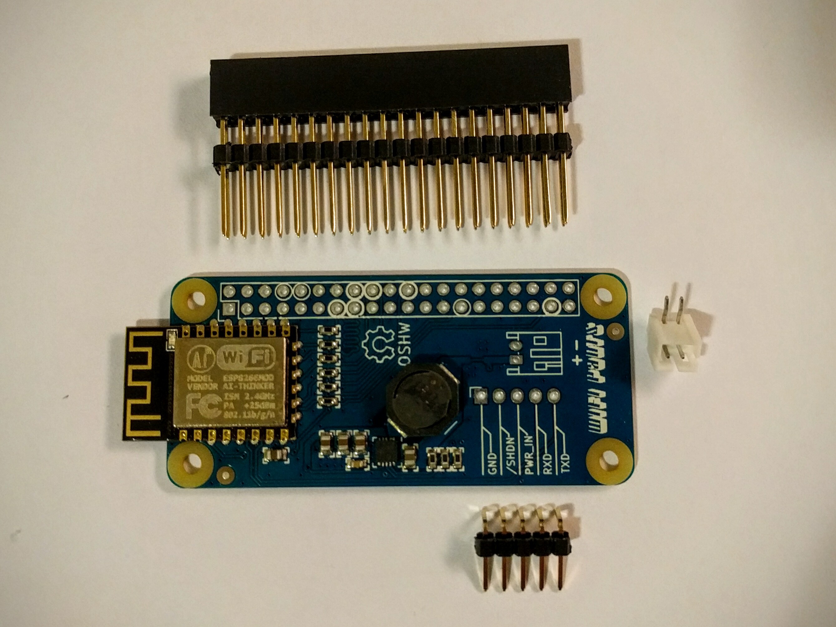
04/07/2016 at 17:24 • 0 commentsNow all the parts for my first small run of boards are sitting in a box on my bench, and I've built up a test board. This is what I plan to sell:
![]()
The headers are shipped unsoldered to allow for different assembly options and to simplify packaging. Ignore the plastic spacer on the header, as it can be removed. I'm not in a place to stock a ton of different options, so if you want to mount this underneath a Zero you'll need to find a different header.
Based on suggestions kindly offered by others, I'll be selling three kits: "full" with everything above, "basic" with only the WiFi populated on the PCB and including all the headers except the JST, and a bare PCB.
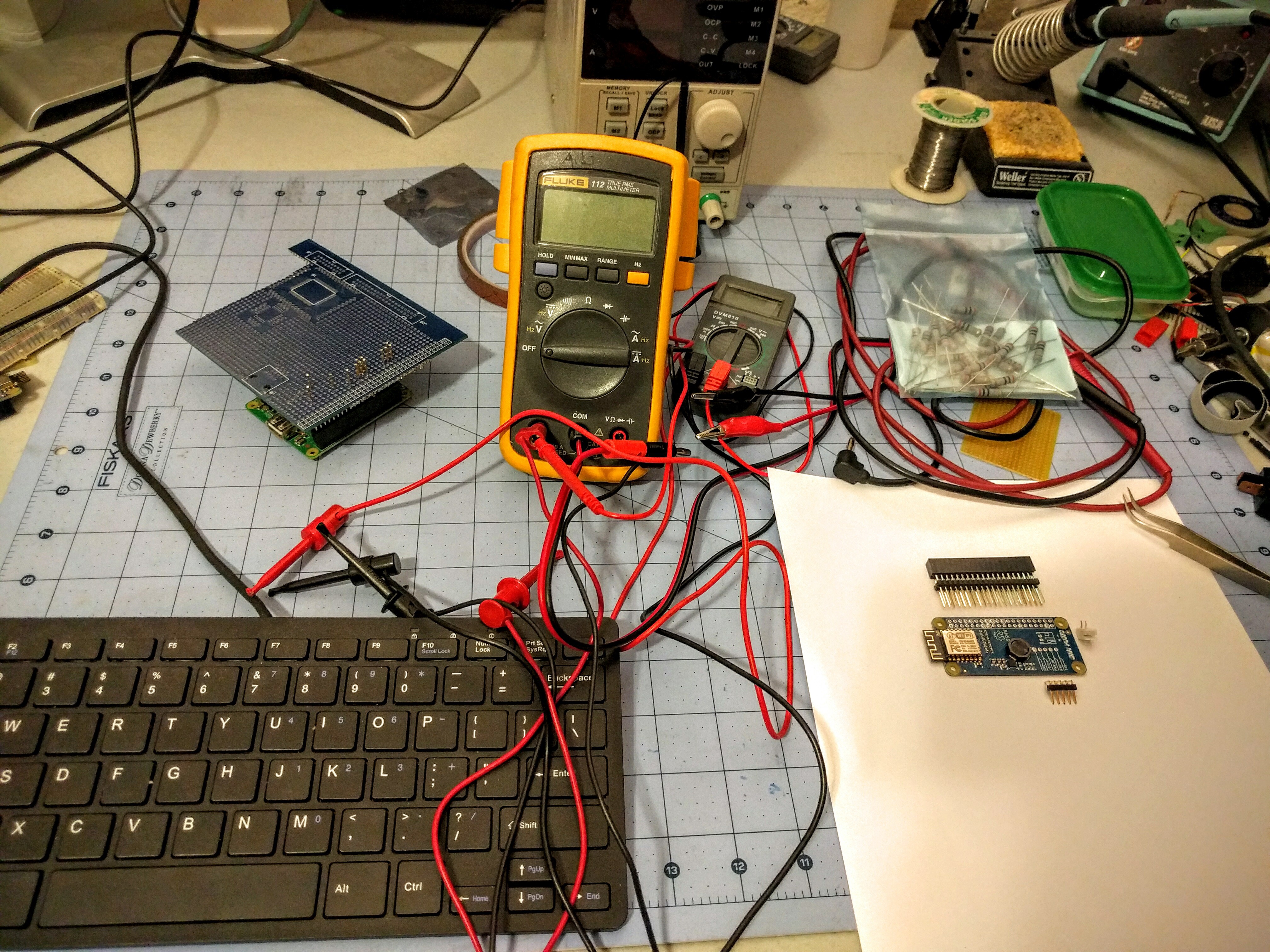
Although I have materials in hand to crank out boards, I need one critical tool in place before production starts. I want these board kits to work once customers solder them together, so I'm working on a test jig for running the SDIO interface and power supply through their paces. After many years of getting along without a real bench supply, I invested in a nice Korad 30V 5A programmable linear that I can use with a pile of power resistors to run the 5V output to 2A at various input voltages, and to test the undervoltage lock-out. I also got a couple of cheap-o DMMs from Fry's over the weekend for a rough output voltage check, and some miscellaneous bits and pieces to put it together. I intend customers to use this board to run motors, LEDs, and other current sucking peripherals, so I want each board tested at load.
Eventually I'll have a printed frame for the PCB and stand to take the load off the Pi underneath. I plan to have this working this weekend, and to start cranking out boards.
I can't give any estimates when this will go on sale. March was exceptionally busy, and I've had little free time to work on this, and April is shaping up to be more of the same. But I'm making progress which I'll continue to share here.
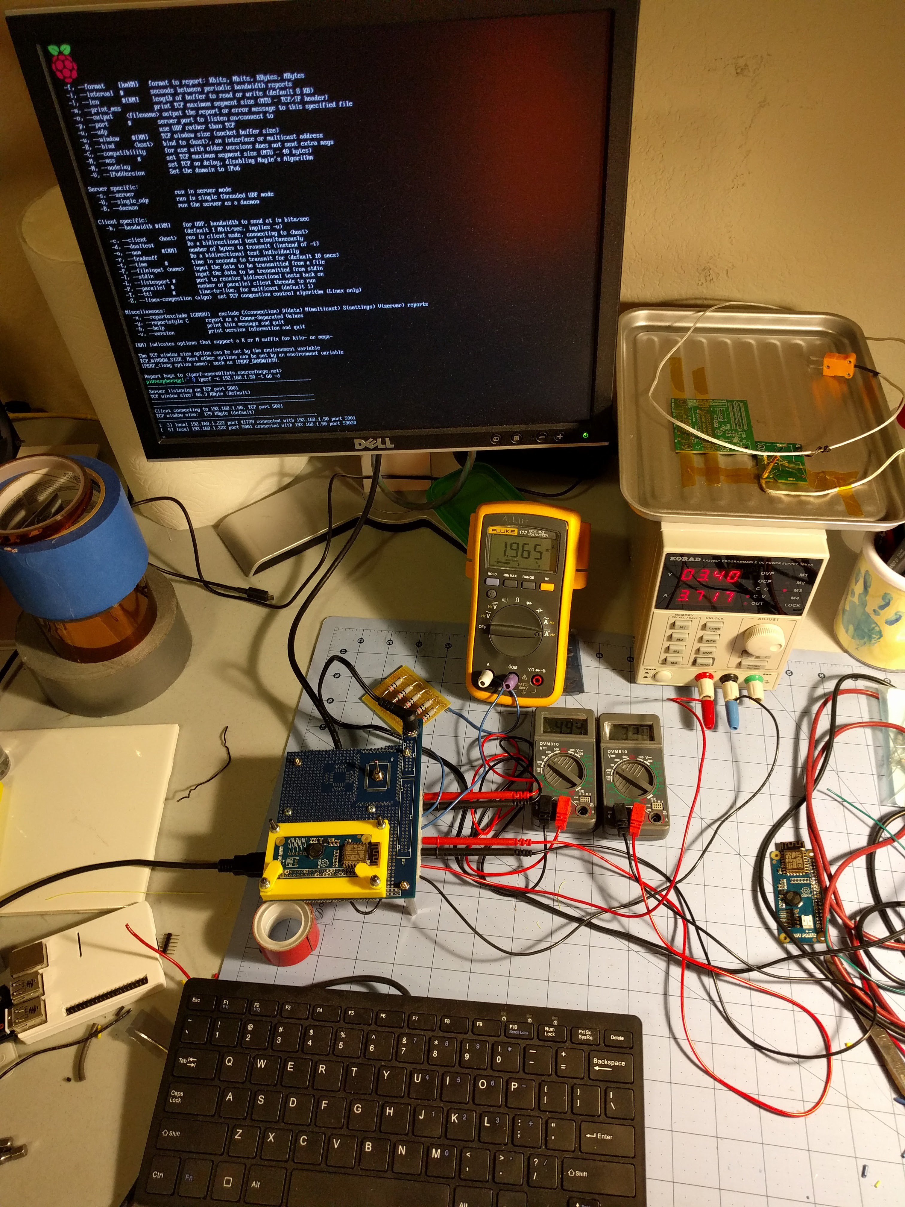
In the meantime, enjoy this picture of my messy bench:
![]()
-
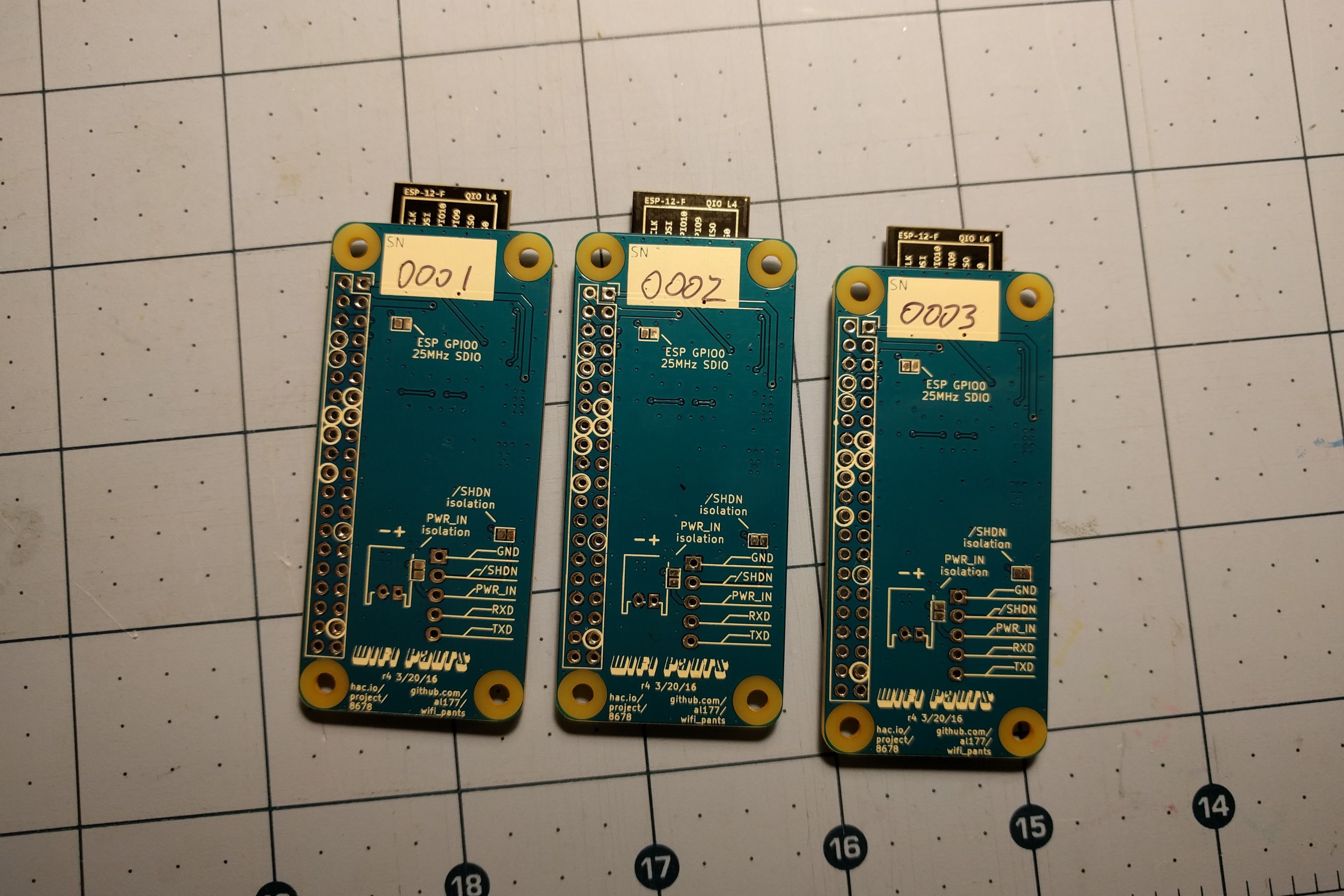
Surprise boards
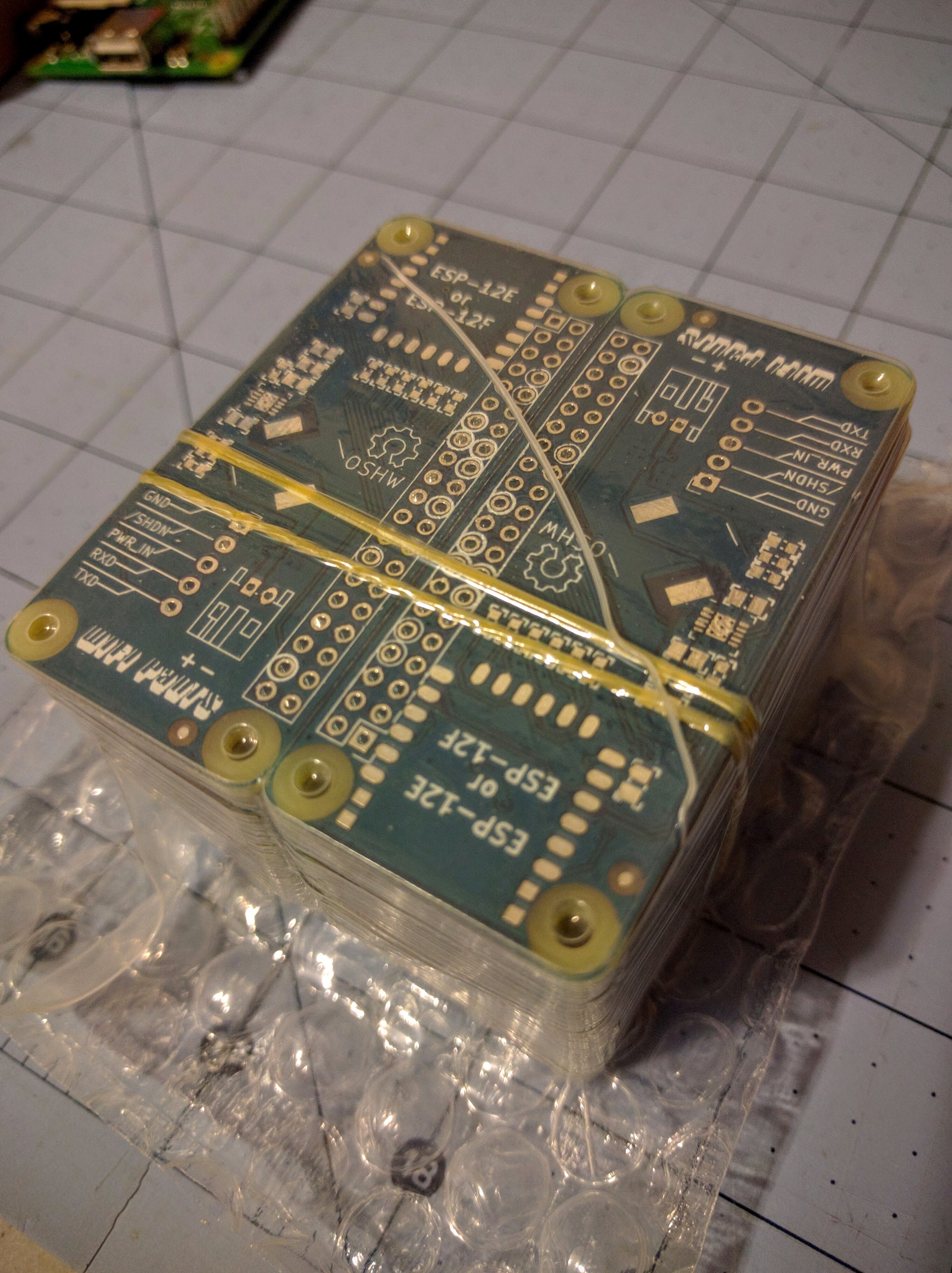
03/26/2016 at 21:26 • 4 commentsUp until now I've been ordering OSHPark quick turn proto boards because they're cheap for very low volume. For the initial Pants run I went with Elecrow in China from the good reviews I've heard. I put in the order last week for 50 Pants boards with 3 day shipping to the US.
DHL just notified me that I should expect them on Tuesday. But I'm totally unprepared. I don't have stencils, I'm missing some of the more expensive parts, I don't have a Tindie account set up yet, I haven't figured out shipping or packaging, I don't have a test jig built yet, and my bench is a mess! I don't know why, but I didn't expect 50 PCBs to be manufactured, shipped halfway across the world, and delivered in under 10 days!
update - and here they are:
![]()
-
On the loss and renewal of focus
03/21/2016 at 05:08 • 0 comments(TL;DR: spent a few weeks on a tangent eating my own dogfood, finalized PCBs and ordered a bunch)
Spring Break is always full of distractions for me. The kids are out of school, work slows down a bit, and South by Southwest takes over Austin, TX. A few weeks ago I got an email from @Sophi Kravitz asking if I might have any hacks I could bring for a panel she was giving at SXSW Create. Naturally I wanted to show off this project, but it hadn't occurred to me 'til then that I had built exactly zero projects using the WiFi Pants board.
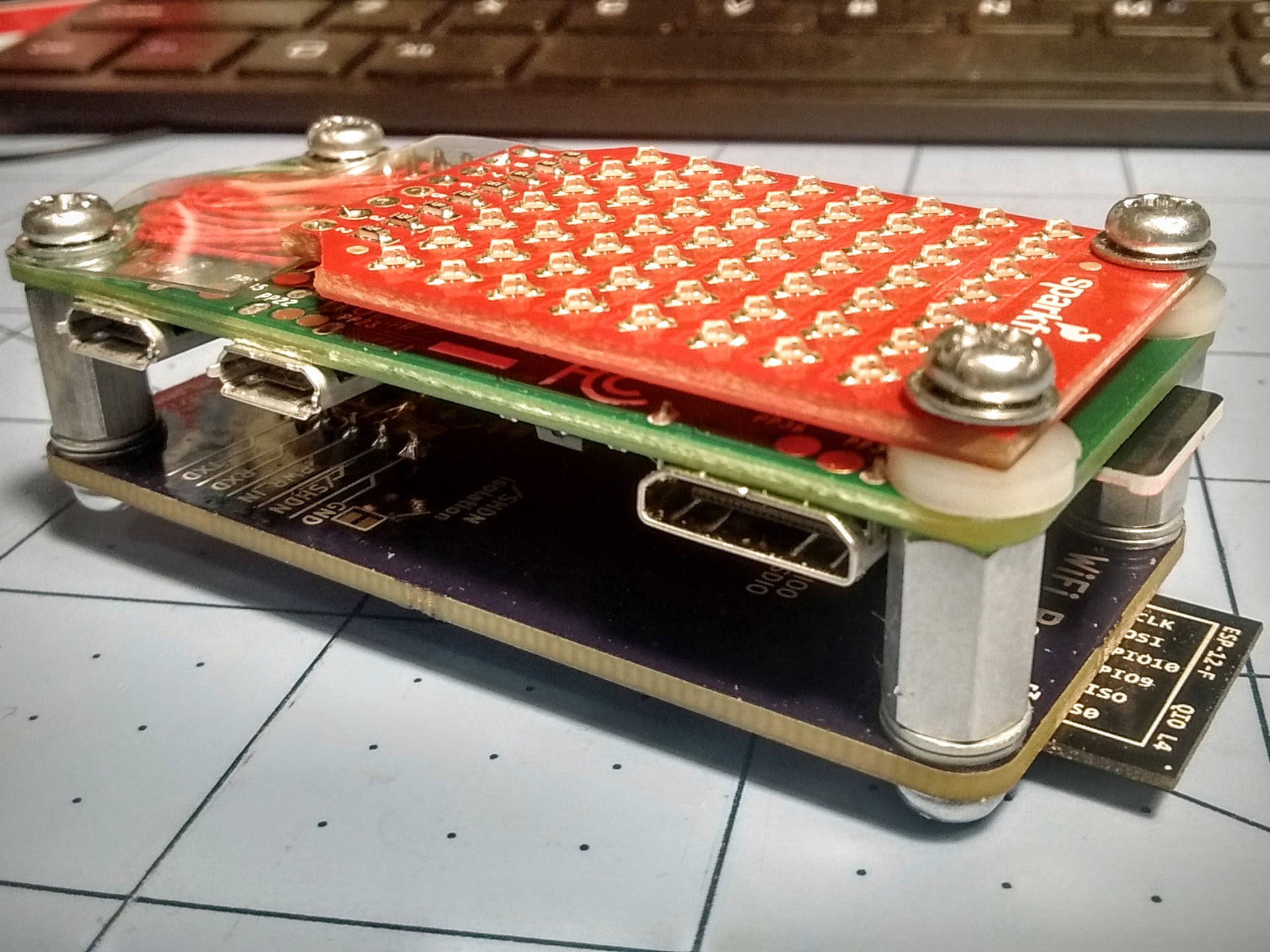
The board isn't that interesting by itself or on a headless Pi, so I wanted it to do something flashy. It needed to be battery-operated to show off the boost converter. So I turned to my junk bin for inspiration, and made a simple LED scroller with the LED matrix from Sparkfun's BadgerHack swag they gave out at last year's SXSW (thanks again!):
I... uh... went a little crazy on this. I didn't expect the show-and-tell to be anything more than what it was: a short demo during the panel. But somewhere along the line I got it in my head that it needed to be a polished looking gadget and not a pile of boards and bodge wire.
I spent a few late nights building the board stack and designing a 3D printed case. The Sparkfun LED array has mounting holes on 23mm centers, conveniently matching the Zero's screw holes, so I scrounged some washers, standoffs, and screws from my junk box and point-to-point soldered the array to end up with this:
![]()
Initially I wanted to fit a small LiPo pouch in between the Zero and Pants board, but I ran into a few problems. I couldn't just go down to the local hobby shop and grab a battery for a nano quadcopter. I needed a protected cell to compensate for forgetting the UVLO (under voltage lock-out) programming resistors on the switcher on this board rev. Failing to have either cell protection or UVLO on the switcher could drain the battery too far and lead to surprise fires of the sort I'd like to avoid. Unfortunately there seemed to be a run on cells with the characteristics I wanted: reputable seller, fits in a 45x23x6mm volume, has protection, big enough for 1hr runtime (>=400mA), and fast enough shipping to get here in time. It seems that the sorts of batteries I wanted were all snatched up by hackers making one of the DIY Zero-based Gameboy projects.
I ended up sticking a 3-AAA battery holder to the back of the case. I used 750mA NiMh cells which consistently give 2:15 runtime with the scroller running constantly. It wasn't as pretty as it would have been with a LiPo, but it worked and was likely safer. I had to make changes in the case model to make the battery connector accessible from the outside, but otherwise it worked well.
The software is all Python. I could have done a C userspace daemon or kernel driver to make the display scanning smoother, but I didn't have time and figured a 1GHz CPU could handle it. It is multithreaded though, with the display scanner / scroller in its own thread that relies heavily on sleep() for timing, and the main loop and Twitter checker in the parent. There is a little flickering when the CPU is loaded, but it's not too distracting and only seems to show on feed updates.
The case was modeled in OpenSCAD and printed in translucent gray (actually thermochromic "hypercolor" plastic) filament. The front of the case is .8mm thick, acting as a diffuser for the display. The thin front is a bit fragile, but it survived the demo. I did print and carry around a second copy the day of the demo though. The insides are lightly friction-fit to the screw heads on both sides of the body, and has stops inside to prevent putting stress on the protruding ESP-12F module antenna. A friction fit lid and hoop for attaching to a lanyard finishes it off.
So this is great and all, and I hope some of the audience found it interesting, but what about making some boards available for sale? Last night I put in an order for 50 PCBs, and will get stencils and additional components ordered soon. The r4 revision has some prettification of the silkscreen, adds the UVLO resistors to the power supply, and makes the option to share the battery positive with the 5 pin header disabled by default to limit the number of opportunities to short out a battery.
Based on the great suggestions I got from the comments in the last log, I'll be making only some of the boards with the boost power supply onboard, with the rest having only WiFi, and will put up additional bare PCBs for sale.