 Dave Gönner
Compromise
One part missing from my description so far is the part that does the actual timekeeping. I am a bit reluctant to publish this, as I consider it the least 'pure' part of the design. Every other part of the clock only uses old technology: Relays, diodes and resistors. But this small PCB has a microcontroller, crystal, real time clock IC, two MOSFETs, a lythium battery and a microcontroller. Those are all quite modern components. But every design has compromises and this is where I made most of them.
Timekeeping
I wanted the clock to keep accurate time, otherwise, what good is it? What I needed was one clock pulse per minute to the minutes section. When the minutes rolled over from 59 to 00, that could be detected and a clock pulse to the hours section could be generated.
I considered multiple options to do this. From reading the 50Hz net frequency and dividing it down, to using a synchronous motor to generate a pulse once per minute. In the end I opted for using a real time clock and crystal and a microcontroller to generate the clock pulses. There is no carry circuit from the minutes to the hours. The microcontroller generates a separate clock pulse for the minute and hour circuits.
Schematic
Below you see the schematic of this circuit board. In the top left is the DS1337 real time clock. This does the actual timekeeping. It has a battery to continue operating when the power to the clock is disconnected. To the left is the DS32KHZ crystal. It is a very accurate temperature compensated crystal, that is supposed to be 2PPM accurate. That is just over a minute deviation per year!
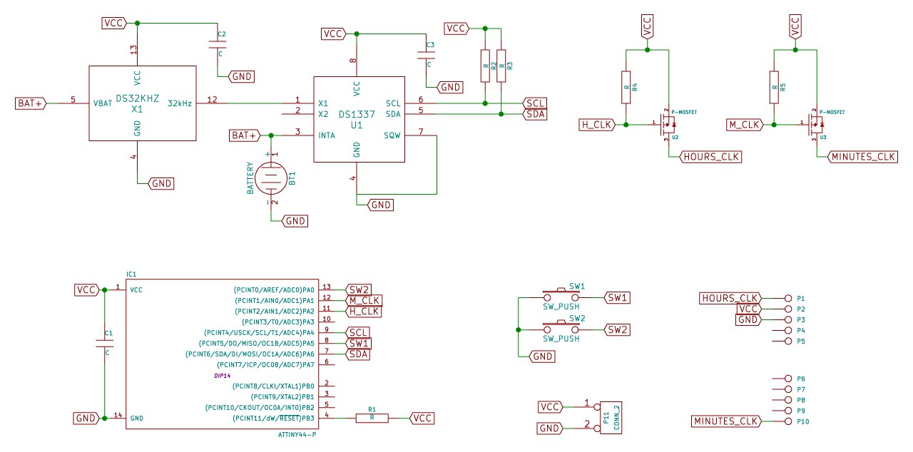
In the bottom left is the Atmel ATTiny44 microcontroller. It read the time from the RTC via the I2C bus. The microcontroller drives two MOSFETs, who supply the clock pulses to the rest of the relay clock circuits. I chose MOSFETS instead of relays to save space and because these relays would wear out quickly.
Functionality
The microcontroller continually reads the time from the RTC. When a minute rollover is detected, it outputs the clock pulse to the minute and/or hour circuits. The two pushbuttons are used to set the time. One for the hours and one for the minutes. Whenever a button is pushed, the minute or hour is incremented and the seconds are zeroed. This allows for accurate timesetting.
One last gimmick I implemented is a showy power up sequence. The relay counter circuits start at 00:00 when the power is connected. The microcontroller starts with incrementing the minutes first and then the hours. It's just a nice little element to show off the mechanism to someone.
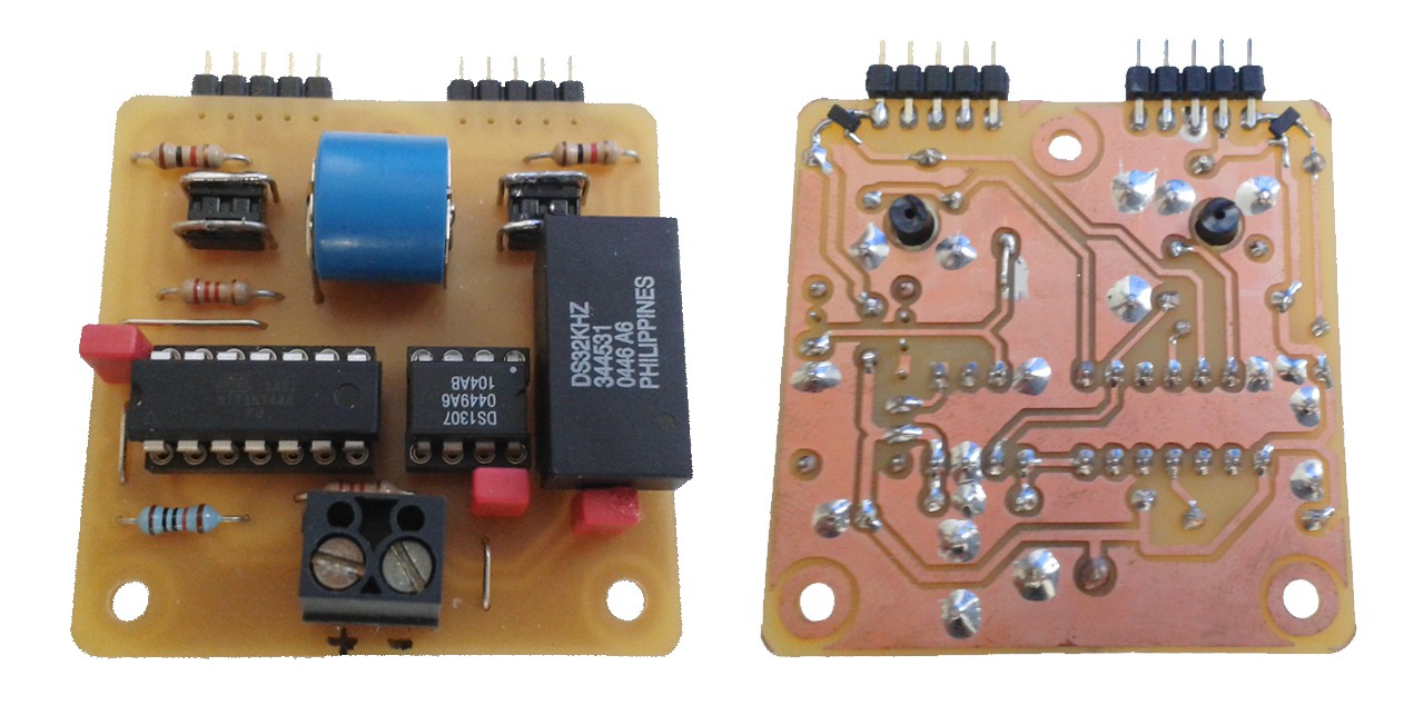
Above you see the finished circuit board. The soldering on the MOSFETs is a bit dodgy and I may redesign it later to use a different RTC. The Maxim DS3231 looks like a nice candidate. It's just as accurate, but has an integrated crystal. For now I am happy with this though.
Discussions
Become a Hackaday.io Member
Create an account to leave a comment. Already have an account? Log In.