 hkdcsf
Operation
On the videos below you can see the currently implemented effects:
On the video below you can see how XMAStar behaves when the button is pressed:
On the video below you can see how XMAStar behaves on under-voltage:
My goals with this project
I wanted to learn the usage of Altium's Circuitmaker. Looking back it was a great choice. After the initial learning period Circuitmakeris a quite powerful free tool for PCB design.
I wanted to build a circuit that is powered with a DC-DC converter using 1 or 2 AA or AAA battery.
For a time I had this little project in mind so I wanted to realize it in this year.
When I was in my early teen years I build a similar star for Christmas. It was a great project. It used discrete transistors to switch the LED's, the transistors were controlled by an up-counter, running from an RC oscillator. It is great to see how technology and my knowledge advanced during the years so now I can design such a circuit with a DC-DC converter, micro controller and current generator based LED driver.
Objectives
- run the circuit from AA batteries
- have at least 1 day of continuous operating time
- use a DC-DC converter
- control the LED's with current generator based LED driver
HW block diagram
On the picture below You can see the HW block diagram.
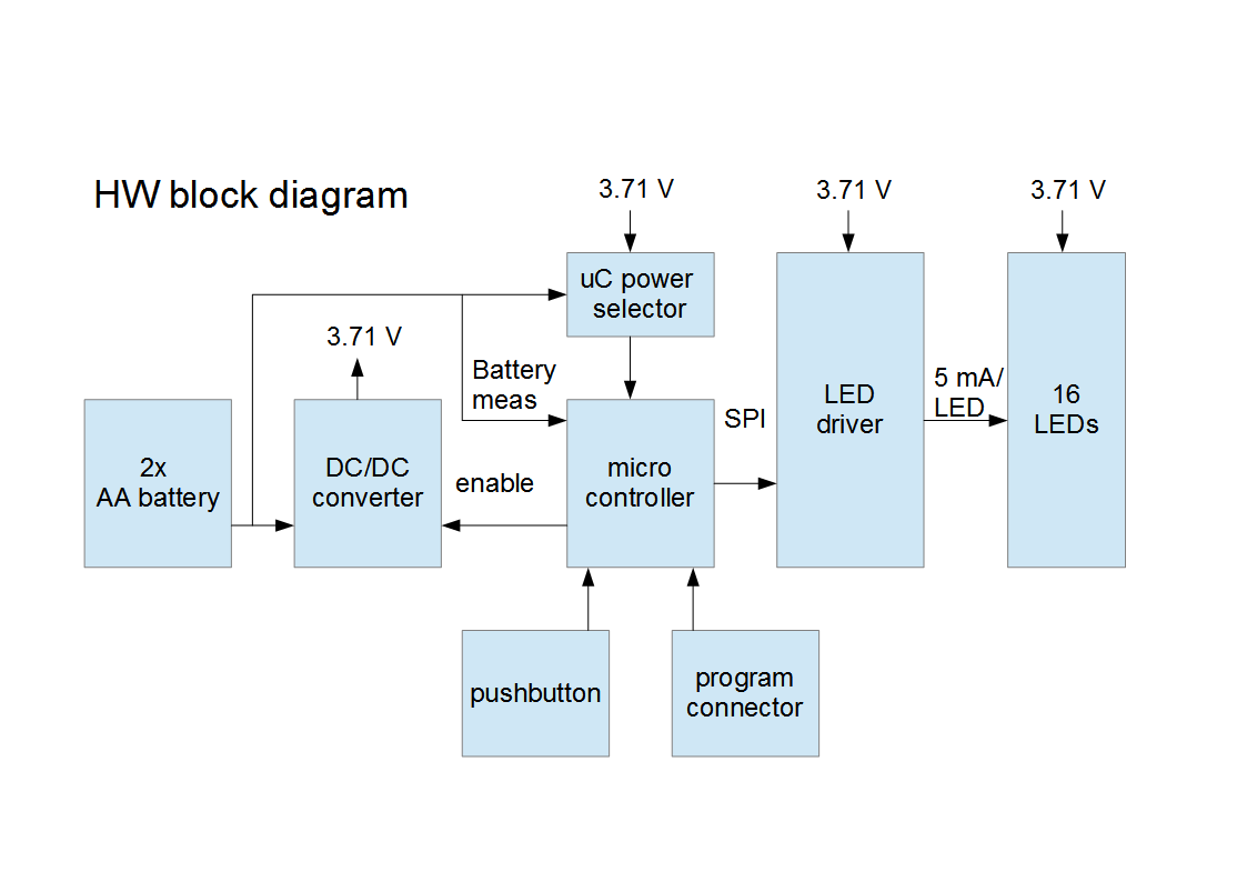
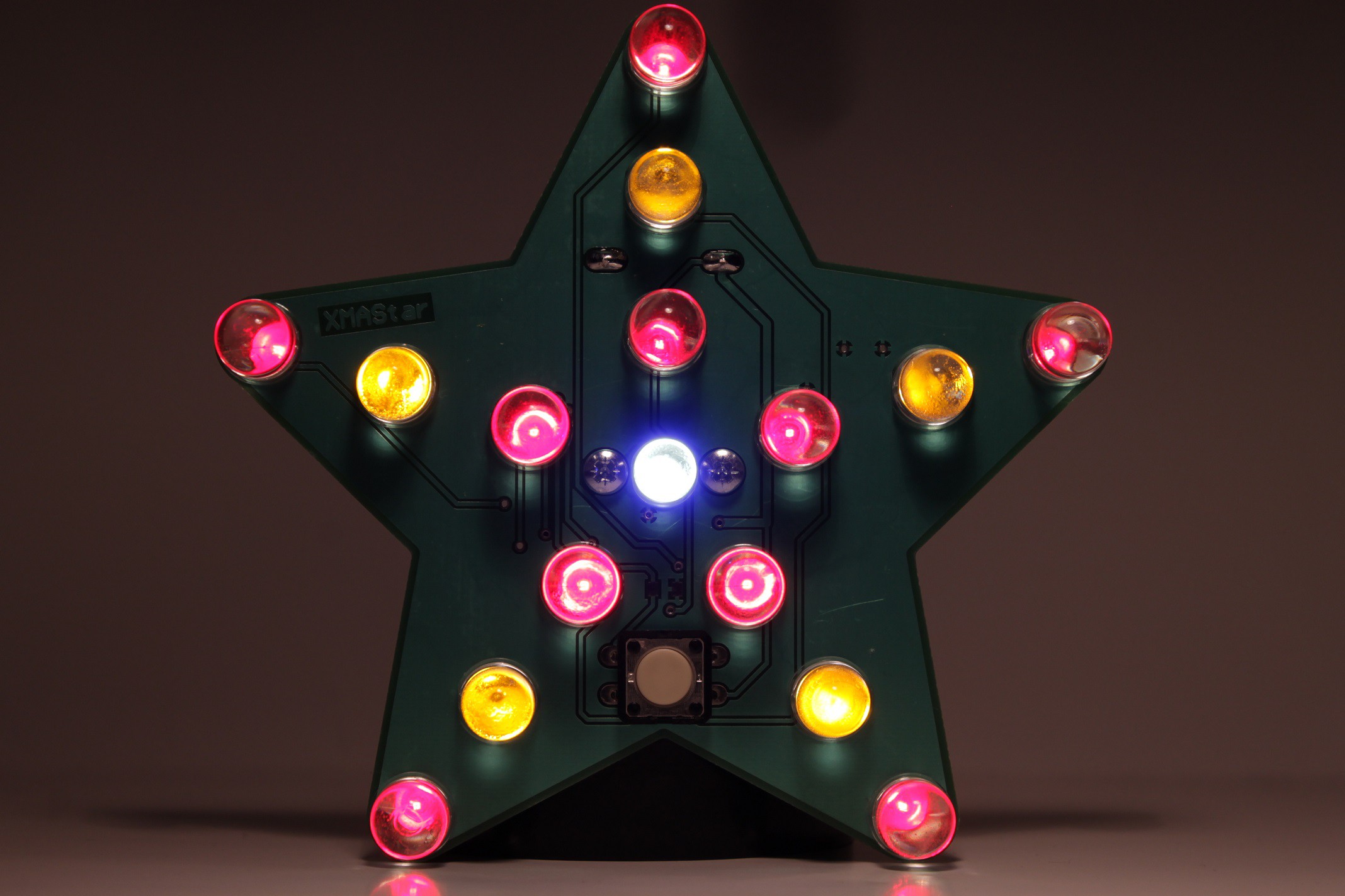
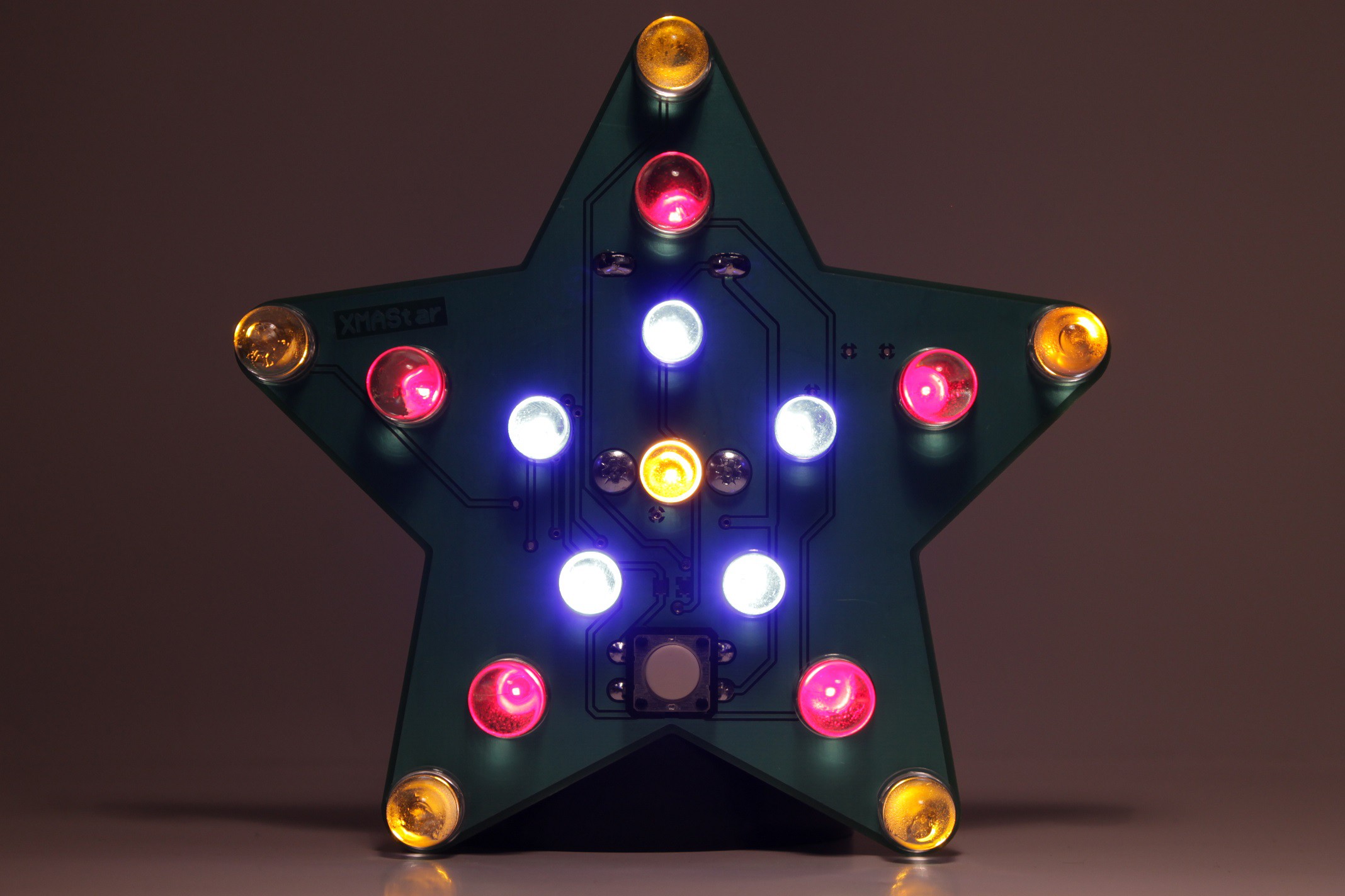
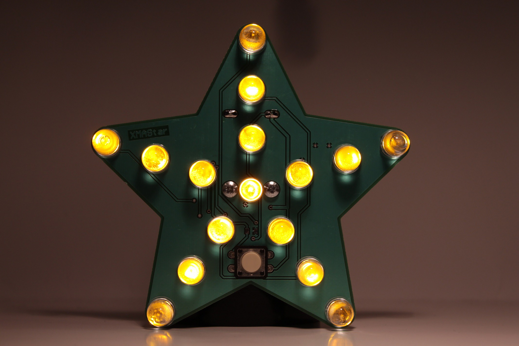
16 LED's are organized in star shape. The circuitry is switching on-off these LED's in various order to create fun visual effects. The color of the LED's are blue, red, yellow and green. I choose through hole LED's because the bulb size of through hole LED's are generally bigger than the SMD ones.
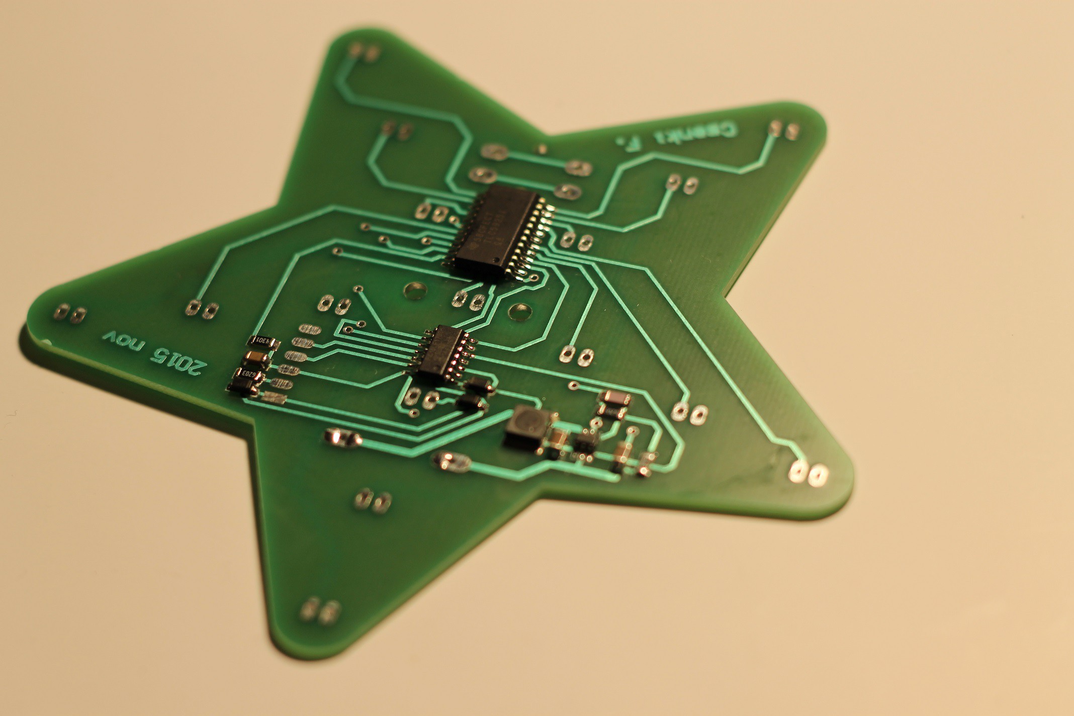
A LED driver IC is used to switch on-off the LED's on SPI commands, and to set the operating current of the LED's to 5mA.
The XMAStar is powered from two AA size battery (Alkaline, NiMH or NiCd). The AA size batteries are chosen because they have a relatively small size, has sufficient capacity to run the circuitry continually for at least 1 day (see the calculation later). Also good AA size PCB solder-able battery holders are available.
The voltage of the two batteries are not sufficient and stable enough to power the LED's therefore a DC-DC converter is used. It converters the battery voltage to fix 3.71V.
Note 1: 3.71V is chosen because the forward opening voltage of the blue LED's can be above 3V, the LED driver needs a minimum 0.6V to operate therefore voltage is chosen above 3V+0.6V
In sleep mode the DC-DC converter is disabled to save power. In disabled mode the DC-DC converter disconnects its output from the battery, therefore the LED driver and the LED's are not supplied, the DC-DC converter consumes around 1uA in sleep mode.
There is power supply selector for the micro controller. In sleep mode when the DC-DC converter is disabled the micro controller is running directly from the battery. If the DC-DC converter is enabled the micro is running from the DC-DC converter output. The power supply selector is implemented with two Schottky diode.
There is micro controller which has three main functionality
- it sends SPI commands to the LED driver to switch on-off the LED's in various orders
- it handles a push button.
- it checks the voltage of the batteries, if the battery voltage drops below a certain level than the micro switches off the DC-DC converter and enters sleep mode
Since in sleep mode the micro runs directly from the battery a low power type PIC is used: PIC16LF1703 which can operate down to 1.8V.
Note 2: the upper voltage limit of this type of micro controller is 3.6V, subtracting the voltage drop on the power supply selector Schottky diode from the 3.71V supply voltage we are just below this limit.
There is one push button connected to the micro. By pushing this button the speed of the LED switching can be adjusted and the circuitry can be put in sleep mode. Meaning of push button presses respectively :
“Low speed state” → “Medium speed state” → High speed state” → “Sleep state“ →“Low speed...
Read more »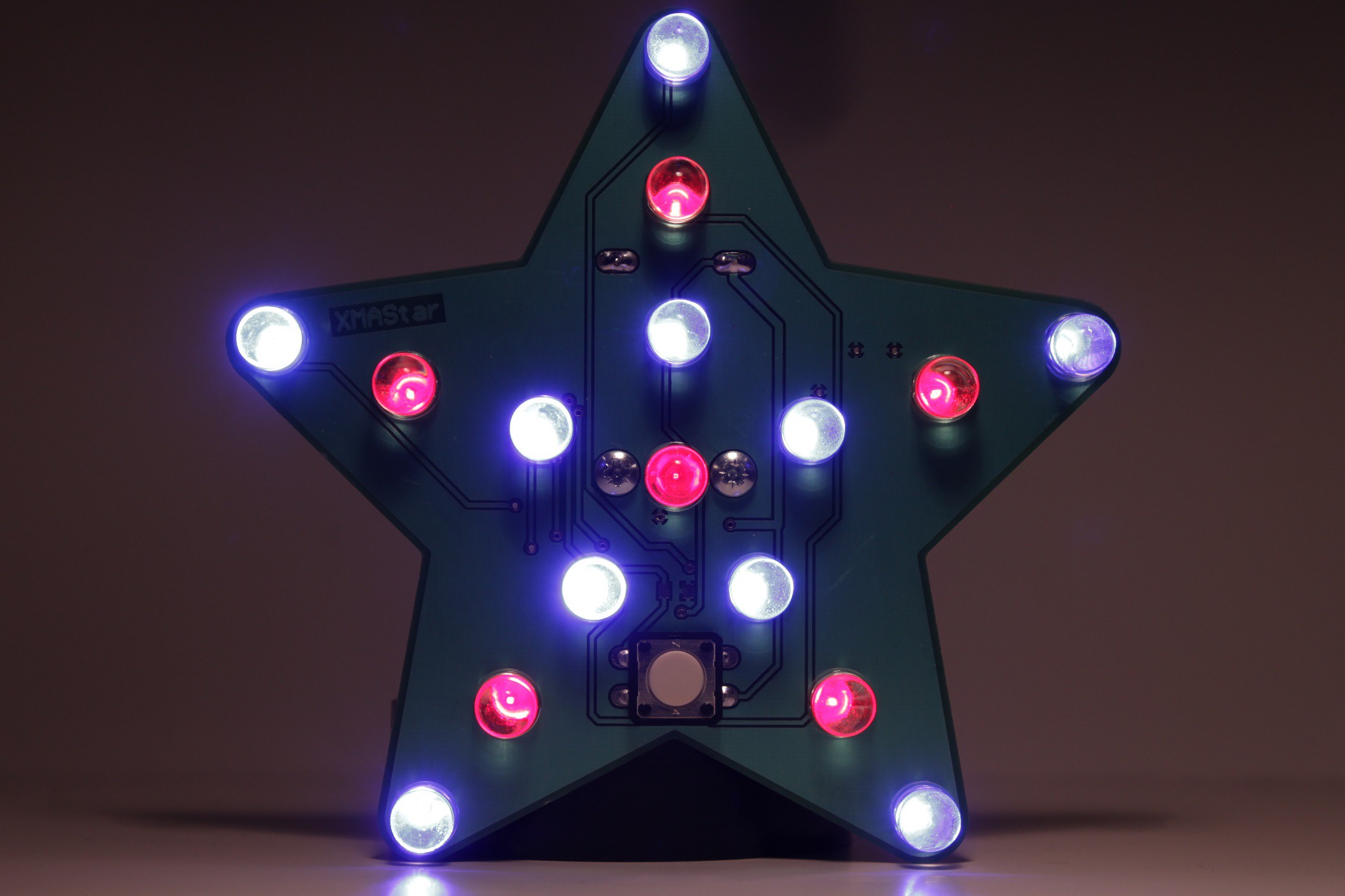


 RoGeorge
 Sam Ettinger

 Tim
Tim
Hello. Where can I download the hex file?
Thank you.