The Smart Letterbox
Attach a device to an existing letterbox that will send a push notification when a letter or package is inserted
Attach a device to an existing letterbox that will send a push notification when a letter or package is inserted
To make the experience fit your profile, pick a username and tell us what interests you.
We found and based on your interests.
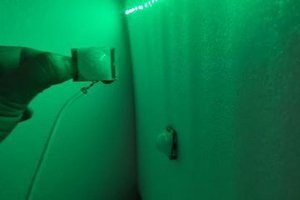
The Adafruit IR Break Beam sensor comprises two components; an emitter that generates an IR beam and a receiver that is sensitive to the IR beam. When the beam from the emitter is broken the receiver pulls its digital output low. The receiver's digital output is open collector therefore the input mode for D4 and D6 were set to INPUT_PULLUP to keep them normally high.
Read more »The DFRobot Vibration Sensor uses the same type of coil mechanism inside to detect vibration. This sensor has a normally-high digital output which goes low during a vibration. I took the MCU with the sensor out for a field test with my letterbox. An LED was wired to switch on when a vibration was detected. Whilst knocks and taps were detected, inserting letters and pamphlets into the top tray did not cause a strong enough vibration to be detected by the sensor. Power was supplied by 2xAA batteries.
Read more »More structured details to come. Some quick notes:
Tried the Adafruit vibration switch (purchased from Core Electronics) to see if it can be used to detect the insertion of a letter/package in the letterbox. It comprises a metal pin with a soft spring coiled around it. When it is moved the coil touches onto the pin, essentially behaving as a switch.
Read more »
Create an account to leave a comment. Already have an account? Log In.
Others have also been trying to answer the question of how much power is required. Interesting the variation observed over changing supply voltage. From 3.1 v to 4.1 v sleep current varies 22uA to 680uA.
http://forum.makehackvoid.com/t/esp8266-operating-voltage-range-and-sleep-current/286
The spec sheet for the ESP8266 quotes the following current draw at 3.3V supply -
Parameters Min Typical Max Unit
Tx802.11b, CCK 11Mbps, P OUT=+17dBm 170 mA
Tx 802.11g, OFDM 54Mbps, P OUT =+15dBm 140 mA
Tx 802.11n, MCS7, P OUT =+13dBm 120 mA
Rx 802.11b, 1024 bytes packet length , -80dBm 50 mA
Rx 802.11g, 1024 bytes packet length, -70dBm 56 mA
Rx 802.11n, 1024 bytes packet length, -65dBm 56 mA
Modem-Sleep① 15 mA
Light-Sleep② 0.9 mA
Deep-Sleep③ 10 uA
Power Off 0.5 uA
Thinking ahead - you need to think about how you will integrate with Apple HomeKit. Homebridge (https://www.npmjs.com/package/homebridge) could be an option.
Thanks, Alisdair. Definitely something to consider adding. It would be neat to ask Siri what the temperature & humidity is on demand.
I think the basic ingredients are a solar panel (to collect energy and provide as electricity), a battery to 'smooth' the supply of electrical energy over time, and a charging circuit to keep the panel and the battery 'harmoniously engaged'.
A key determinate of the specs is the power required to run the rest of the solution - expressed as a required voltage level and the peak and average current (or power) required. I guess the power required characteristic could be complex to express if the solution has many states with different power requirements.
The power provided by the solar panel will vary with the degree of exposure to the sun. Have recognised our latitude is one factor. Others include how overcast are the weather conditions, the temperature of the panel, the efficiency of the panel. For example can we assume, worst case, deep in winter we get, at most, 3 consecutive bleak days where nothing is generated.
We could then use this worst case to determine how long the battery needs to power the device and hence the capacity required, taking into account the type of battery. Different battery types have different desirable discharge limitations if we are to maximise the battery lifespan.
The type of battery also impacts the charging circuit if we are to maximise battery lifespan. For example NiMh charging should be limited by current supplied and does not mind a degree of very low current overcharging, whereas lithium ion can stand high current charging but does not like being overcharged at all. And the ideal charging characteristics will vary over the charging cycle potentially adding complexity to the charging circuit.
There are units available that combine the panel, battery and charge circuit but they appear relatively expensive. For example - http://www.multipoweredproducts.com.au/products/Solar-Technology-Freeloader-iSIS-Solar-Battery-Pack-%2d-ST-FL5001.html.
I ran some tests powering the NodeMCU + DHT22 using 4xAA (1.5V) batteries which dropped to 5.8V under load. During WiFi transmission it peaked at 70 mA. Will try 3.3V next as I believe that is all we will need.
A physical requirement for the solar/battery combo is to support a retrofit onto an existing letterbox with minimal footprint and to appear as least conspicuous as possible.
A flexible solar panel like the one Pete linked to below would be ideal to "stick" onto the lid of the letterbox with varying shape. The battery and MCU would sit inside the letterbox.
There are cheap Lipo chargers (like this one http://core-electronics.com.au/solar-lipo-charger-3-7v.html - and associated battery http://www.dfrobot.com/index.php?route=product/product&filter_name=3.7&product_id=437#.VpzlwDbexhW) that may help with overcharging.
We may be able to drop current down to 30-50mA when not transmitting but powered. Sleep mode could bring us down even further if we can figure out how to wake MCU from a letter insertion event.
I bought a cheap solar/battery from eBay (http://www.ebay.com.au/itm/381443248689) that appears to work OK. It supplies 5V via USB output. Haven't tested how long it will last and whether the solar panel charges the battery sufficiently to keep the unit going for a long time. I'm also not sure if the battery is being charged whilst power is being consumed from the USB output.
Formulas to calculate sunlight per geo-location. http://astro.unl.edu/classaction/animations/coordsmotion/daylighthoursexplorer.html http://physics.stackexchange.com/questions/28563/hours-of-light-per-day-based-on-latitude-longitude-formula
Solar power.
Can we squeeze in smart meter electronics under 100 mA. Could this panel charge a LiPo batter?
This one is even smaller and is 3.6V at 100 mA. Whilst it may be able to power the NodeMCU at maximum sunlight it may struggle to charge a battery. Not sure. Wish we had someone looking into the power solution. (-;
Looks like it supports a few connection methods: "Connection methods include soldering, crimping or using alligator clips"
Is there a standardised set of conditions / tests used to show the comparative output of such components? Yes we need to work from the sunlight conditions of a lat/long to the battery to the solar cell.
Become a member to follow this project and never miss any updates

 electronicsworkshops
 Hulk
Hulk
 hIOTron
This article has encouraging results. Almost dont need a solar panel.
Verify measurements and calculate total power usage over time: The scope
is calculating the area as 174.2mVs. So with a total wakeup time of
about 2.6s that would be an average of 66mA current draw while being
awake. With 4 wakeups/h what would give 0.19mAh (4*2.6s/3600*66mA). The
rest of the hour sleeping would draw 0.022mAh, resulting in 0.212mAh
total. With 2500mAh AA NiMH (low self discharge, assuming 80% after 1y)
that would be about a year (ignoring step-up losses).
http://vt100.at/blog/?p=22