 John Boyd
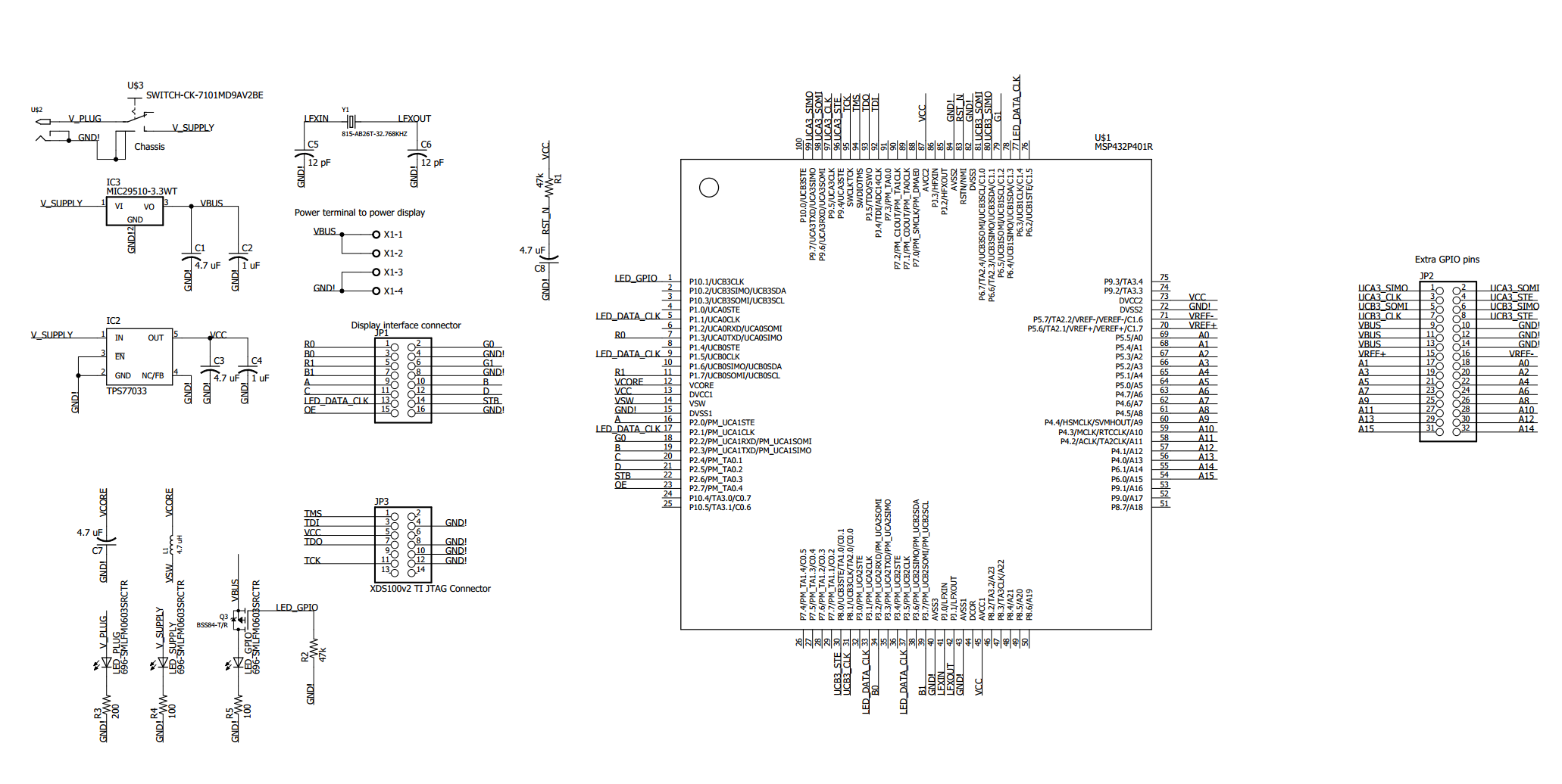
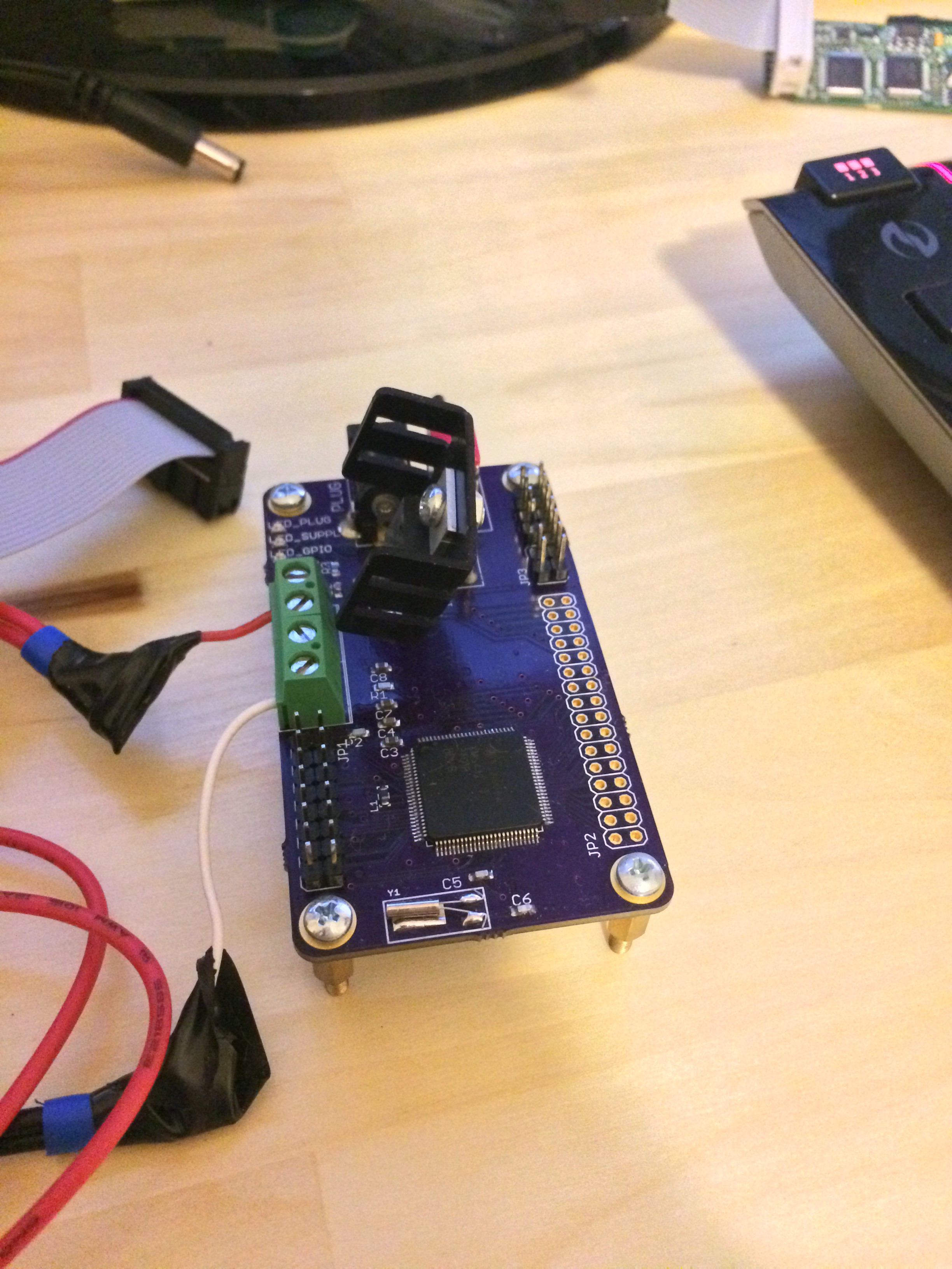
The hardware for this project is relatively simple. Essentially just a the MSP432 with the display connected to its eUSCI outputs and a few GPIOs. The challenging part of this project was designing the firmware in a way to leverage all of the MSP432 peripherals to reduce the computational requirements for the CPU. To do this, the firmware does the following:
- A graphics driver subsystem comprised of:
- Multiple timer interrupts trigger frame transmission as well as LED PDM pulse widths, etc
- 6 eUSCI SPI peripherals with interrupts to continuously drive the display without active control from the MCU
- DMA controller handles large memory transfers from the main program to the graphic's driver.
- A state machine to manage events as the CPU returns from several interrupts at any given moment.
The firmware is posted on github for those looking for more details.


 RT-Thread IoT OS
 sjm4306
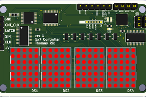
 Thomas R