 Yann Guidon / YGDES
This is a module that #Hackaday TTLers and other CPU makers often need: they can spy on an address or a data bus without the hassles of a logic analyzer. Which is fabulous when developing the #YGREC-РЭС15-bis or the #Discrete YASEP...
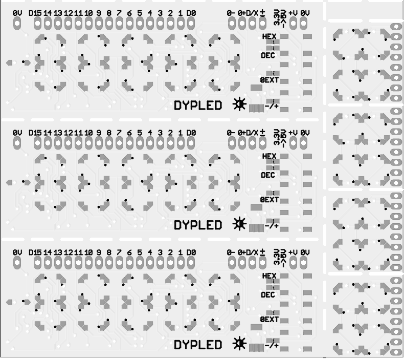
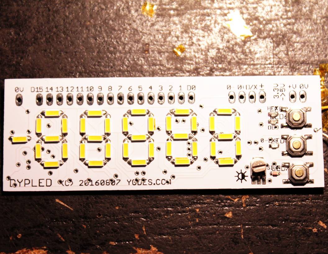
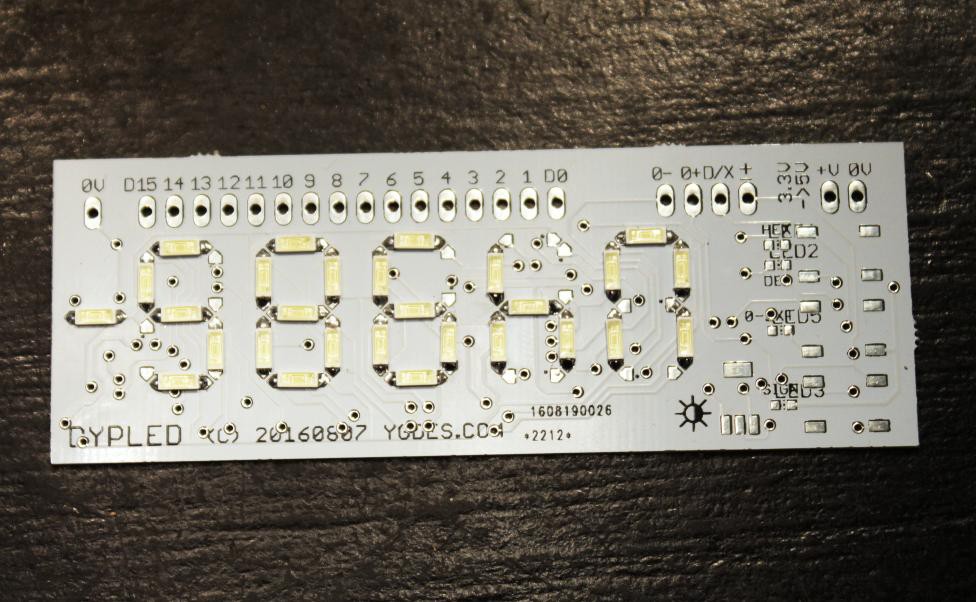
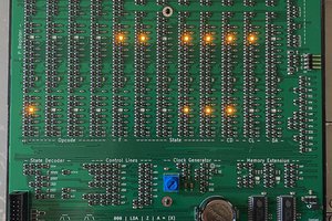
The PCB acts as a display panel with 5 7-segment digits, 3 push-buttons to select the modes, one adjustable resistor to set the brightness and a row of pins that connect to the circuit under examination. The interface is pretty simple:
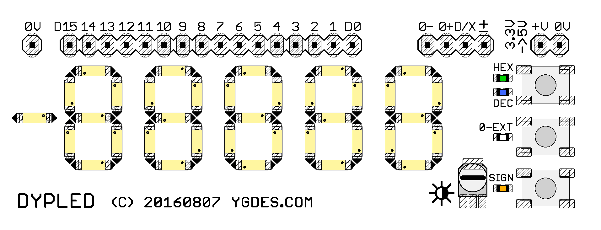
Original sketch: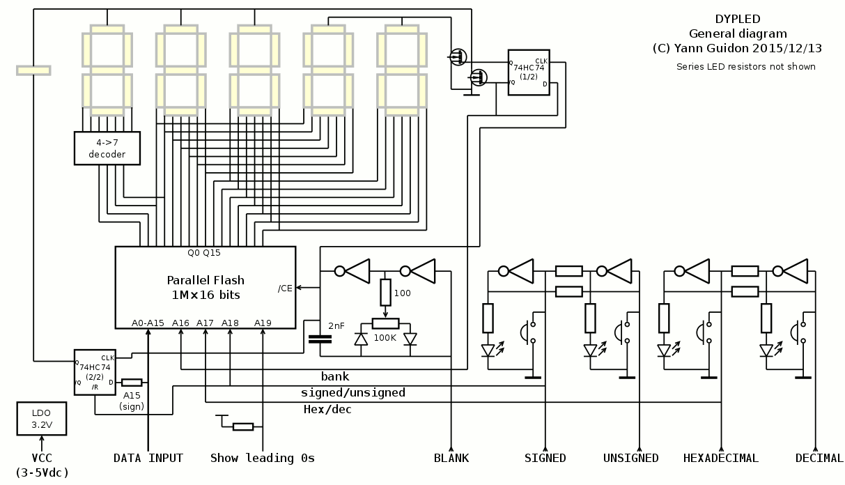 Schematic with Eagle:
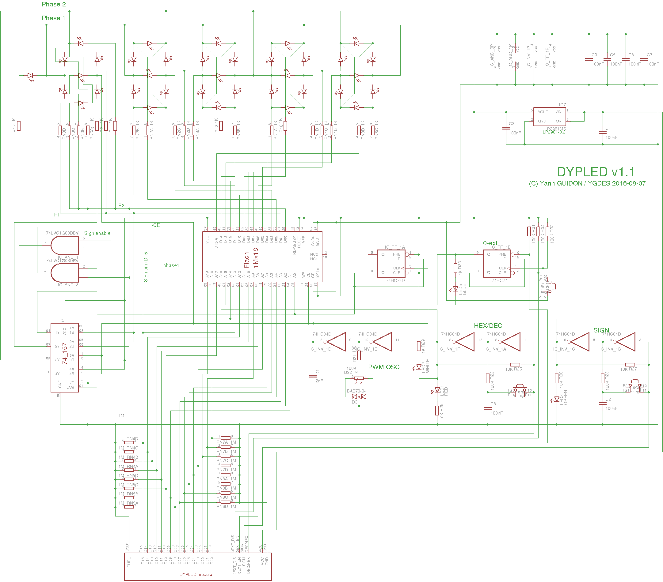
This is a sub-project of the #Discrete YASEP, which needs a dozen of displays that are
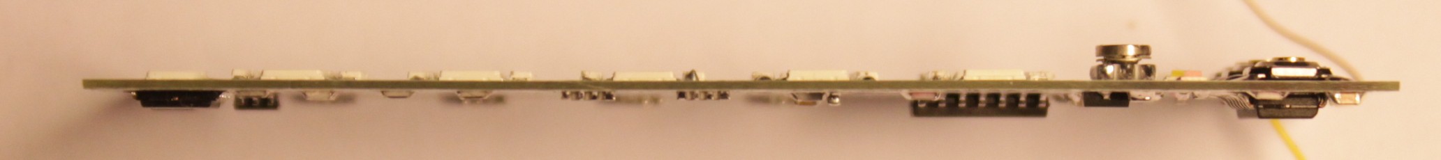
- very thin
- as cheap as possible
- nice-looking
- not power-hungry
- easy to build/solder
I have looked at the different possibilities here, here, there, I've looked at the TIL311 integrated hexadecimal display and even started a project to create a modern, cheap clone (#PICTIL)
@al1 turned the #PICTIL into a very nice entry for the #The Square Inch Project but I need something different, not a faithful TIL311 drop-in replacement. Something that shows what we can actually do in 2015 ;-)
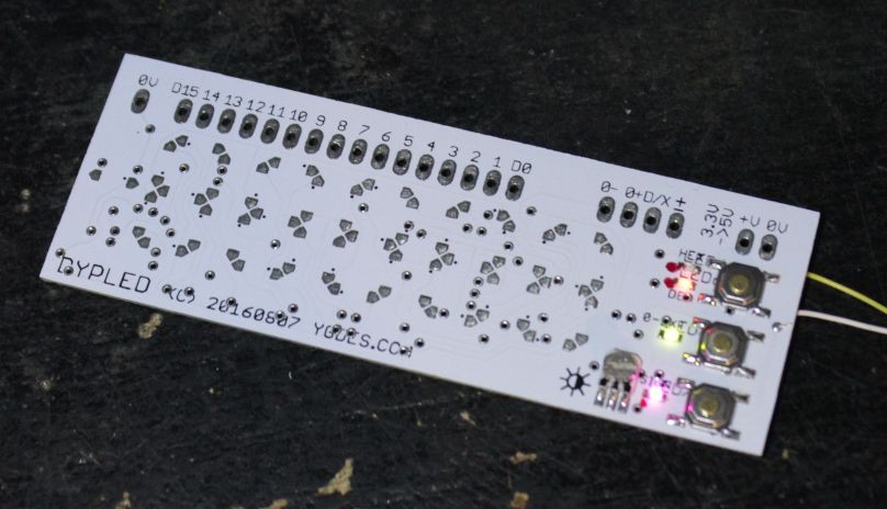
My requirements are fulfilled by the (niche) 4014 LED format. The comparison with the TIL311 proved promising so I made more experiments, resulting in a first prototype of 7 segments module.
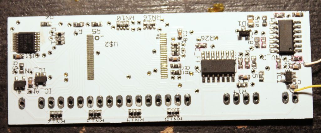
I solved the decoding issue with a brute-force approach: a 1M×16 Flash chip. Some web-hunting found very cheap lots from brokers and it turned more flexible and cost-effective than other approaches (microcontrollers, CPLD...) thanks to the great pins-vs-price and combinatorial agility (and no need of VHDL or assembly language and proprietary probes to program it).
I found a little lot of very cheap AT49BV162A that have the very nice feature of being 5V compatible. It's an ideal match for this project: users don't need to worry about input voltages, it works with both 3.3V and 5V systems without adaptation. The other integrated circuits work with a wide voltage range. The module also operates with a power supply as low as 3V (it's actually limited by the LED's brightness). An integrated LDO limits the internal voltage to 3.2V.
Dimming is implemented with PWM with a semi-analog oscillator (using the cheap 74HC04). This also drives a divide-by-two counter (74HC74) for output multiplexing. This divider has complementary outputs that drive the appropriate MOSFET (which alternate in grounding their own phase rail).
The unused gates from the 74HC04 implement FlipFlops that select the display mode.
The sign bit is copied directly from the input's bit n°15, ANDed with the sign mode bit (trough a MUX2 in a 1G157 chip).
The last gotcha is the decimal mode which requires a fifth digit (ranging from 1 to 6). Compared to the previous hex-only design, the MOSFET are driven by the 74HC74 so this frees 2 data output lines, that turn into 4 lines when demuxed. A 74HC157 performs the additional decoding.
Also keep in mind, that members of the "puritan TTL Nerd fraction" may sneer at you for juggling with lookup tables beyond 1MB.
Logs:
1. Decoding the extra digit
2. Cost optimisation
3. Little enhancements
4. A dumb bistable
5. Adjustable PWM oscillator
6. Some updates
7. Preliminary layout
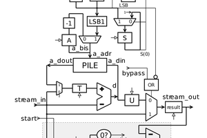
8. Stack-based programming
9. Tiny progress
10. Alternate uses
11. Small change
12. Other changes
13. New layout, new schematic
14. Dual-mode display
15. Autorouters are for the weak
16. Enhanced multiplexing
17. Another module
18. Generate the Flash's contents with a recursive algorithm
19. Bit shuffling: what goes where ?
20. Number conversion
21. File generation in C
22. Not a failure but not a success either
23. First prototype
24. Resuming
25. Decoupling
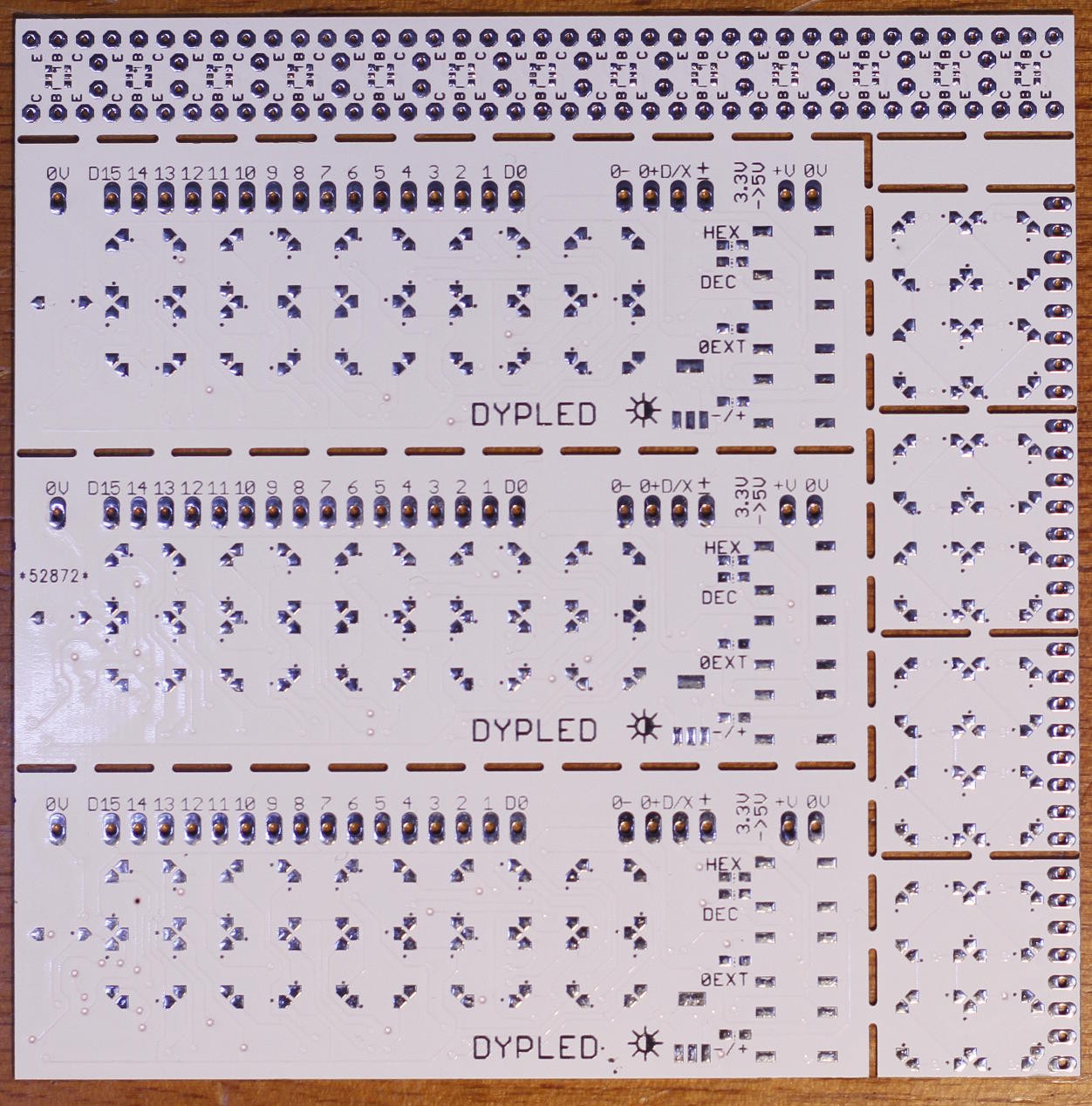
26. PCB rev.2
27. Another spinoff
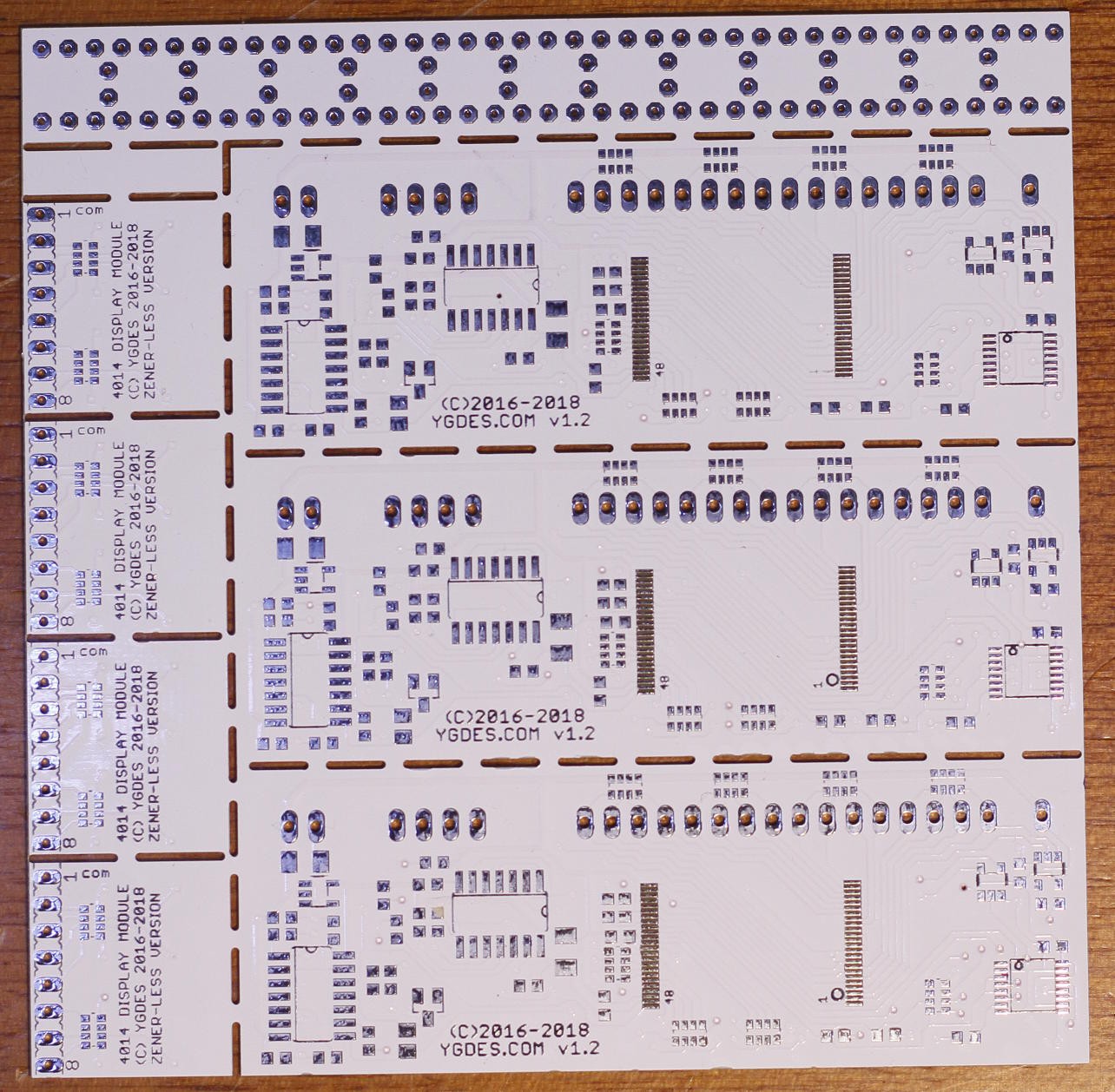
28. New batch
29. New batch delivered !
.
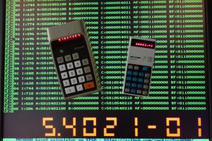
 Time to test the other circuits !

 Joe Wingbermuehle
 zpekic
I just realised that "negative hexadecimal" is awkward...
Without the limitation of the 5th digit, I would implement an octal mode :-D