 Yann Guidon / YGDES
The most delicate piece of electronics in this project is the variable duty-cycle oscillator. It has two functions : drive the divide-by-two flip-flop to alternate between odd and even addresses (output LED multiplexing) and also dim the LEDs (through the /OE pin of the Flash chip).
The frequency should not change much because the output multiplexing should be smooth, well above 1KHz. Only the duty cycle (percentage "on") should change so this precludes a lot of variable frequency oscillators.
So I started from the #Charleplex Xmas Tree without uC oscillator topology and remembered a little "trick" I saw while looking at other oscillators recently. I have already played with asymetric oscillators so I was familiar with using two diodes to select one resistor for one phase, and another resistor for the other phase. What I saw is to instead use a trimmer where the brush is the common output and the diodes are on both ends. This keeps the average resistance almost constant, the frequency does not change much but the high vs low time are proportional to the brush position.
There is another problem as well. The eyes have a logarithmic response but SMT adjustable resistors are linear only. This reduces the "interesting" range to a small angle of rotation. My solution is a very high ratio between the trimmer's value and the series resistance that controls the minimum on and off time.
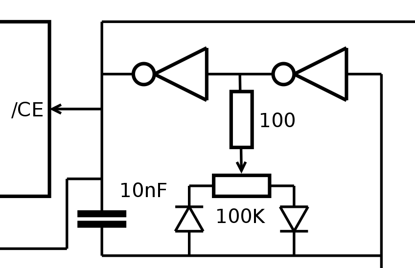
In my experiments, I found a reel of 100K Ohms trimmers. I started with a 1K series resistor but that was still too high. 100 Ohms provide a 1/1000 ratio and the luminosity is still good when using a LED without series resistance (and I'm not counting the 1/2 duty of multiplexing).
The diodes are Schottky in SMB package. I don't have anything else, it's not the thinnest but the trimmer is the less thin device in the module (1.3mm thick) so it's not so important.
For the frequency, 100nF oscillates too slowly, I see flickering. But 10nF is good. Varying the duty cycle changes the frequency by 20% at most, I suppose that the diodes add non-linearities. I measure about 1200Hz. It's not yet divided by 2 and I think 600Hz is too slow so I'll try to find 2nF caps.
At 1.8nF, the frequency is around 6KHz, or 3KHz after the mux divider. No flicker is perceptible.
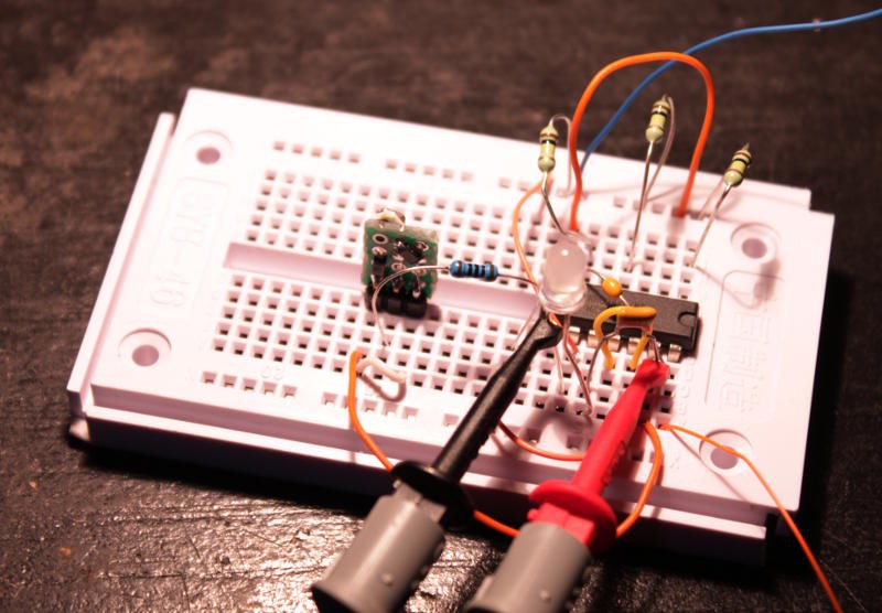
I soldered the SMT parts (diodes and trimmer) on a small proto PCB. The trimmer is not easy to adjust but it's not something that would be operated often...
20170429:
@Frank Buss found a study about pulsed LEDs (see PWM test) that shows that flicker can be perceptible up to 3KHz so my experiments seem to be vindicated :-)
Discussions
Become a Hackaday.io Member
Create an account to leave a comment. Already have an account? Log In.