-
Bit shuffling: what goes where ?
08/18/2016 at 22:46 • 0 commentsln the last episode (Generate the Flash's contents with a recursive algorithm), I defined the general algorithm to generate the Flash's contents. It accepts arbitrary permutations. Now, the question is to generate the proper permutation vector.
From what I have coded, it is obvious that the algorithm must be taken from the hardware point of view to give the logic address. In other words, we take the list of Flash pins (in order) then lookup what it corresponds to.
At least, I did something right: bit 0 of the Flash address selects the high/low word so there is no need to recompute the logic value twice :-) The computation cost is halved again and each "leaf" of the recursive algorithm will output 4 bytes.
Now on to the other address bits:
Flash    Function
addr
 bit

 0   High/low word
 1   D09
 2   D08
 3   D07
 4   D06
 5   D05
 6   D04
 7   D03
 8   D12
 9   D01
10   D13
11   D00
12   D14
13   D15
14   SIGNED/UNSIGNED
15   0-EXT
16   HEX/DEC
17   D10
18   D11
19   D02
Now if the mode bits (SIGN, 0ext and Hex/dec) were in the LSB, that would save even more computations (good to know for next time) but.... K.C. Lee will complain again that I over-optimise (not that he's wrong buuuut...). In the end, routing has had the last word.
Anyway the code becomes a bit more interesting because there are those 3 modes to manage, in the middle of the permutation vector. This gives me the idea to select the conversion function not with a "if" at the leaf level, but by passing a function pointer, just like the "logic" address parameter. Some may cringe but this saves some coding efforts, it is more elegant to me :-)
Once again, this is not about writing the fastest algorithm but to make the leanest conversion functions. Reducing the number of (iteratively redundant) IF statements is a high priority because it makes the code more modular. Propagating attributes in the recursive calling stack keeps the system conceptually simple and safe (no kludge), despite the increased stack occupation (which takes a toll on CPU+memory).
So where are we now ?
- Hex/Dec is managed by propagating a function pointer to the conversion function. Start recursing with the HEX code, then when index 16 is found, replace the function pointer with DEC code.
- Signed/Unsigned... let's keep it simple, one IF won't kill me because it will just select a little line. Another propagated parameter is added to the growing list of arguments...
- 0-extension : that's another matter which affects both the HEX and DEC code, which creates 2 IF in two different functions (potential bug alert). The idea is simple too : recursively propagate a "default" value of the display, which can be null or 0000. When the leaf functions will add digits, they (unconditionally) will clear the default value and overwrite the digit.
The last part tells us that writing a digit will be done by a single function, called by both HEX and DEC conversion functions. Modularity for the win :-)
Now, on to the next puzzle !
I want to reduce the number of IFs in the leaf functions and the recursive code. But the modes will require more code inside the recursive functions. Each call would require to go through a switch-case... How can this be kept to the bare minimum ?
I have come up to this system:
   // permutation of the input bits
   var BinLUT=[
     0,   // High/low word, unused
     9,
     8,
     7,
     6,
     5,
     4,
     3,
    12,
     1,
    13,
     0,
    14,
    15,
    -1, // SIGNED/UNSIGNED
    -2, // 0-EXT
    -3, // HEX/DEC
    10,
    11,
     2 ];
The modes are coded by negative numbers so if the number is not negative, the normal (fast) code is executed, otherwise the switch-case is examined. The code becomes "table-driven", the behaviour gets defined by an array of numbers, less by the code itself. This also means that there are less places to check if the pins change.The new recursive function becomes:
   function recurse( index, logic) {
     msg+=" "+logic;
     if (index>0) {
       var bit=BinLUT[index--];
       var mask=1 << bit;

       recurse(index, logic);
       if (bit < 0) {
         mask=0;
         // special code for the modes
       }
       recurse(index, logic|mask) );
     }
     else
       msg+="\n";
   }
There is no else. The mask is simply cleared when a mode is detected. Once again the IF is evaluated once and changes the default value of other statements.Tests show that the "mode" is only entered very infrequently, which justifies embedding the switch-case inside a IF statement (which is easily handled by branch prediction).
A slightly diferent approach is used there:
   function recurse( index, logic, sign) {
     msg+=" "+logic;
     if (index>0){  //0) {
       var bit=BinLUT[index--];

       recurse(index, logic, sign);

       if (bit < 0) {
         msg+="\n ------ " + bit +"\n";
         // special code for the modes
         switch(bit) {
           case -1: sign=1; break;
         }
       }
       else
         logic|= 1 << bit;
       recurse(index, logic, sign);
     }
     else
       msg+="   S="+sign+"\n";
   }
I have traded the variable mask for the else. The logic address is updated only if the if is not taken.I have added the sign parameter and it works nicely. I can test the code easily by changing the range of iteration, progressively increasing the starting value (with the initial call) and the leaf trigger (if(index>threshold))
For example, starting with the value 15 and ending at level 10, I get the following dump:
 0 0 0 0 0 0   S=0
 1   S=0
 16384 16384   S=0
 16385   S=0
 32768 32768 32768   S=0
 32769   S=0
 49152 49152   S=0
 49153   S=0

 ------ -1
 0 0 0 0   S=1
 1   S=1
 16384 16384   S=1
 16385   S=1
 32768 32768 32768   S=1
 32769   S=1
 49152 49152   S=1
 49153   S=1

 ------ -2
 0 0 0 0 0   S=0
 1   S=0
 16384 16384   S=0
 16385   S=0
 32768 32768 32768   S=0
 32769   S=0
 49152 49152   S=0
 49153   S=0

 ------ -1
 0 0 0 0   S=1
 1   S=1
 16384 16384   S=1
 16385   S=1
 32768 32768 32768   S=1
 32769   S=1
 49152 49152   S=1
 49153   S=1
Adding support for zero-extension is pretty easy: the parameter zero_ext is included in the list of arguments.Initially, it is set to 0 (no extension) but in the switch-case, it is overwritten by a magic value (which corresponds to 0000)
   function recurse( index, logic, sign, zero_ext) {
     msg+=" "+logic;
     if (index>10){  //0) {
       var bit=BinLUT[index--];

       recurse(index, logic, sign, zero_ext);

       if (bit < 0) {
         msg+="\n ------ " + bit +"\n";
         // special code for the modes
         switch(bit) {
           case -1: sign=1;      break;
           case -2: zero_ext=42; break;
         }
       }
       else
         logic|= 1 << bit;

       recurse(index, logic, sign, zero_ext);
     }
     else
       msg+="   S="+sign+" Z="+zero_ext+"\n";
   }
Here, I have chosen an arbitrary value because it is not yet defined. I get the following test result:0 0 0 0 0 S=0 Z=0 16384 S=0 Z=0 32768 32768 S=0 Z=0 49152 S=0 Z=0 ------ -1 0 0 0 S=1 Z=0 16384 S=1 Z=0 32768 32768 S=1 Z=0 49152 S=1 Z=0 ------ -2 0 0 0 0 S=0 Z=42 16384 S=0 Z=42 32768 32768 S=0 Z=42 49152 S=0 Z=42 ------ -1 0 0 0 S=1 Z=42 16384 S=1 Z=42 32768 32768 S=1 Z=42 49152 S=1 Z=42Excellent !Now it's the hex/dec's turn. I have chosen the function pointer method but if decimal was not used, then a different approach would have been even more efficient. I'll describe it for the record ;-)
Decimal numbers can change the output radically if a bit is flipped (with the exception of bit 0). There is an avalanche effect. However if you change one bit of a hexadecimal number, only the corresponding digit is affected. Do you see where I'm going ?
Start from the end of the BinLUT array and look which consecutive bits form a digit (4 consecutive bits). We have a 12-13-14-15 at index 8, and 3-1-0-2 starting at index 7. In the recursive function, we can detect if index==7 and compute all those digits, overwriting the zero_ext parameter. Further down, we have the digit 7-6-5-4 at index 3, which can be evaluated too, leaving the digit 9-8-10-11 to the leaf...
This would be pretty efficient if the system only did hexadecimal (or octal) display but the decimal mode is not so kind so I'll implement that trick ... another day. For now, I only forward the "base" parameter:
function recurse( index, logic, sign, zero_ext, base) {
  if (index>0){
    var bit=BinLUT[index--];
    recurse(index, logic, sign, zero_ext, base);

    if (bit < 0) {
      switch(bit) {
        case -1: sign=1;      break;
        case -2: zero_ext=42; break;
        case -3: base=16;     break;
      }
    }
    else
      logic|= 1 << bit;
    recurse(index, logic, sign, zero_ext, base);
  }
  else
    convert(logic, base);
}

recurse(19, 0, 0, 0, 10);
So this, kids, is how I have managed to elegantly reshuffle all the address bits !
Update: it's funny but in the above code, I used an integer argument (base, either 10 or 16) for the sake of simplicity. I would relegate the function pointers for later. However in Number conversion, I realise that it's actually not a problem at all to have hex and dec converted by the same function :-) So I keep the integer parameter...
-
Generate the Flash's contents with a recursive algorithm
08/18/2016 at 02:32 • 4 commentsAs I just sent the PCB to fab, I have a couple of week to wait...
But the design is not over ! The Flash chip must be programmed with a lookup table contained in a file, which must be generated from the pin assignations, and this is not as straight-forward as it seems !
Now let's consider this : the Flash is pretty large, a few megabytes. We can work "in memory" and scan an array in RAM then dump it to a file. But this will take a long time, and cause a lot of cache misses. Yes, I'm an over-optimiser but if you consider that I might implement the algorithm with bash, for extra geek points, a better and leaner approach seems desirable.
I have chosen a "streaming" algorithm that doesn't hold the whole contents in RAM, but writes it to a file as soon as each byte or word is computed.
It's not that complicated, the algorithm might work like this:
- Loop 2Mi times (as many as words)
- For each word:
- compute the logical index from the physical index (the counter)
- compute the value corresponding to the logical index
- translate the value into an output code
- write the code to the output
That's very nice but in practice, it's obviously inefficient because a lot of values will be computed over and over but they never change...
Quite a few things can be precomputed, such as the digit->output code conversion. However, because we are totally reshuffling the address bits, addresses/indices must be recomputed at every cycle.
This computation is actually a remapping of the bits so it's not so arbitrary. If I flip the bit #n, then the bit #m will be flipped in the logical index. This opens an opportunity to save a lot of lookups...
A traditional bit-shuffling routine would loop over all the input bits (let's say 21 because that's how many address lines we have), then for each bit, lookup what is the position of the corresponding logical bit. Since there are 21×2²¹ lookups, that's a long computation overall.
I have found how to cut this cost in half with a little, neat recursive trick. It does not use a loop counter, but a bit index counter. Starting at index 21, for example, the procedure function calls itself twice with the decremented index. So the procedure is called with index 21, but each time with a different parameter. As long as the index is not 0, the procedure calls itself twice, leading to 2²¹ calls, as expected.
Here is a first JavaScript example of a recursive counter:
<html>
 <head>
  <script>
   function start() {
    var pre=document.getElementById("out");
    var msg="Starting:\n"

    // permutation of the input bits
    var BinLUT= [ 4, 2, 5, 3, 6, 0, 1 ];

    function recurse( index) {
      msg+=" "+index;
      bit=BinLUT[index];
      if (index>0) {
        index--;
        recurse(index);
        recurse(index);
      }
      else
        msg+=" *\n";
    }
    recurse(6);

    pre.innerHTML=msg+"end!"
   }
  </script>
 </head>
<body onload="start()">
 <pre id="out">
  empty
 </pre>
</body>
</html>
The output shows that one half of the upper bits are not evaluated, in average:Starting: 6 5 4 3 2 1 0 * 0 * 1 0 * 0 * 2 1 0 * 0 * 1 0 * 0 * 3 2 1 0 * 0 * 1 0 * 0 * 2 1 0 * 0 * 1 0 * 0 * 4 3 2 1 0 * 0 * 1 0 * 0 * 2 1 0 * 0 * 1 0 * 0 * 3 2 1 0 * .....
Now the magic is that the first call forwards its initial parameter (the logical index) but, before the second call, the index is updated with the right bit set to 1. This leads to only 2²⁰ lookups.In the following example, the code performs a bit reversal:<html> <head> <script> var msg="Starting:\n" // permutation of the input bits var BinLUT=[ 3, 2, 1, 0 ]; function recurse( index, logic) { msg+=" "+logic; if (index>0) { var bit=BinLUT[index--]; recurse(index, logic); recurse(index, logic|(1<<bit) ); } else msg+="\n"; } function start() { var pre=document.getElementById("out"); recurse(3, 0); pre.innerHTML=msg+"end!" } </script> </head> <body onload="start()"> <pre id="out"> empty </pre> </body> </html>Starting: 0 0 0 0 4 2 2 6 1 1 1 5 3 3 7 end!As the recursion nears the end, more bits are set. But it works with any permutation, not just bit reversal. -
Another module
08/16/2016 at 01:20 • 0 commentsI still haven't sent the PCB to manufacture, I'm waiting for another project to share the cost. Meanwhile I know I have to develop the software that generates the Flash's contents. I'm also considering another multiplexing method and I'll have to prototype it for the #Discrete YASEP displays. So I made this quick simple PCB:
![]()
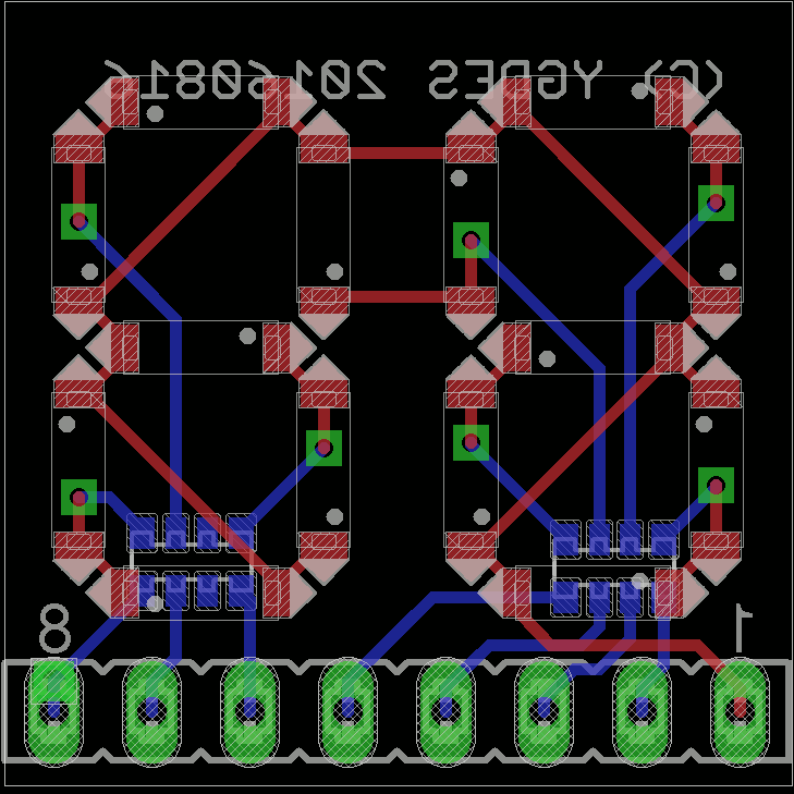
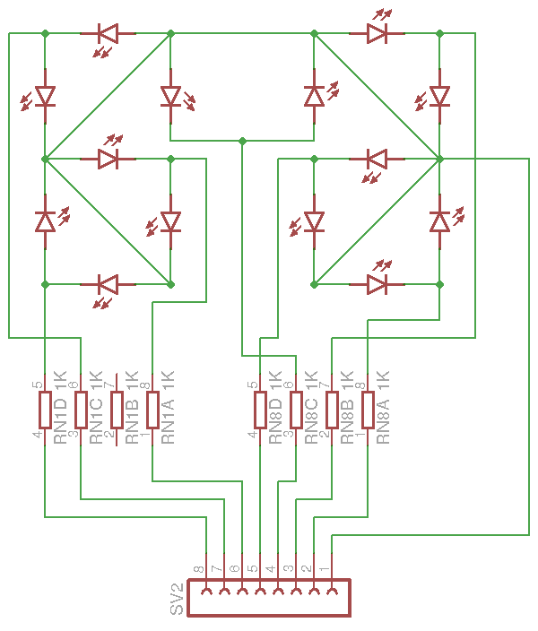
The size is exactly 8×0.1" and the digits can be assembled side by side to create large numbers.
Since it's a more generic circuit than #DYPLED and it can be used in more projects, I consider offering it as well :-)
![]()
It's pretty easy to use and can be driven by a microcontroller, for example, if the Flash/ROM method does not interest you.
Update 20160817:
This minimodule has been forked to #4014 LED minimodule !
-
Enhanced multiplexing
08/08/2016 at 21:06 • 0 commentsIt's too late but the following idea struck me at the last moment of routing.
There is actually no need of two common rails for the display. One rail that is switched from 0 to +Vcc is enough. This would simplify the routing, though in this case, the difference is not important enough to justify rerouting anything. I'll leave it like this but I write this as a "reminder for later".
For now, the system works like this : each Flash pin goes to a resistor then two LEDs, each tied to one of the common rails. The LEDs are wired in the same direction so one of the rails must be set to 0V to turn the corresponding LED on.
This is actually overkill if we realise that the LEDs could be connected in reverse and in parallel, with the single common rail swinging for 0V (to turn one LED on) to +VCC (this turns the other LED on). The only change is to reverse the value of the FLASH memory for one half of the output values.
This becomes more complex since the 5th digit's decoder would require a total redesign as well...
20160822:
This did not work as expected. But all is well that ends well !
Damned protection diodes... -
Autorouters are for the weak
08/06/2016 at 22:43 • 12 commentsI finally completed the place/route work for the module! It took a long time (it started many months ago...) and even though all the parts fit, I wasn't sure the tracks would. Yet there is still a little room under the contrast adjustable resistor. If you're impressed, well, I'm even more impressed that I completed it and respected all the constraints!
Is there an autorouter out there that could do such a crazy job ?
![]()
-
Dual-mode display
07/20/2016 at 01:07 • 0 commentsThe native working mode of the module is "Hexadecimal / Decimal" depending on one bistable button.
For an application such as a simple DDS (like my very own #Quick & Dirty Frequency Generator ) the input value is provided in binary by hex/binary selectors. In this case the mode button can select beween raw divisor value and expected frequency, just by programming the Flash EPROM correctly :-)
-
New layout, new schematic
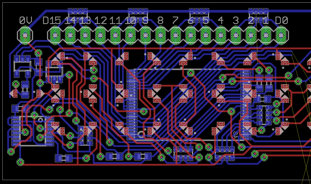
04/21/2016 at 09:39 • 0 commentsI can't believe I did it... It's probably the most tortuous routing I've ever done. You can see by the number of vias, how much efforts I put into avoiding parts on the visible side.
![]() The right side is still not routed and I must triple-check that the logic on the left is correct. I'm so relieved I removed the SC70 MUX and a couple of other parts...
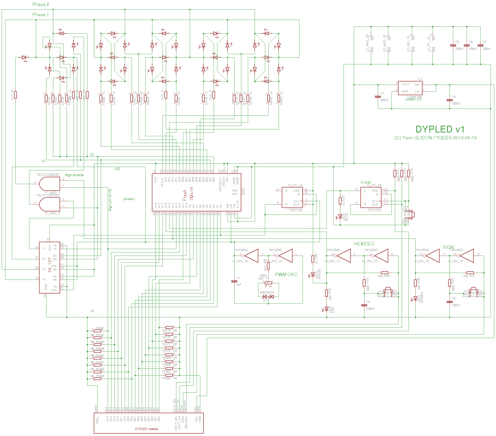
The right side is still not routed and I must triple-check that the logic on the left is correct. I'm so relieved I removed the SC70 MUX and a couple of other parts...The new schematic includes all the previously mentioned changes.
![]()
-
Other changes
04/20/2016 at 18:56 • 0 commentsI am resuming the development of this module so I can finish it ASAP (while several other projects are eagerly waiting :-D). This is a good idea because I have all the required/necessary parts (delivery ended in february) so it won't cost me even more. I don't even know how much I've already spent, when you love, you don't keep scores... So I've had a few months to let the design "percolate" in my mind and I return with a fresh mind, only to find the mess I've done.
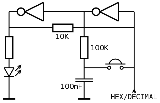
One little detail that changes everything is the single-button flip-flop that I discovered while searching something else for another project (probably flip-flops for the #Clockwork germanium).
![]()
One big advantage is that only one button is necessary and this saves space. Not that I'm space-constrained but the previous board revision was 83mm long, which is unfortunate for panelization in the Europe format.
With only 3 buttons, I have shrunk it to 29×79mm and this leaves just enough margin for milling in a 100×160 board (panelized as 3×2 boards).
This also reduces the number of pins on the connector, but now two functions must be controlled differently. A simple pair of push-buttons does not work as before, there is a risk of short-circuits if both pull-up and pull-down buttons are pressed at the same time (a 1K resistors becomes needed in series with the power supply).
The 5th digit's decoding logic is getting overhauled as well. I'm not happy with the cluster of single-gate chips, they put pressure on routing because of the power supplies, and the 1G157 MUX2 in SC70 is really tiny.
I think I've found a way to use a 74LVC157APWR instead, saving hassles during assembly but this forces me to review all the previous design rationales.
The '157 will also drive the common cathodes of the LEDs, saving a couple of MOSFET in SOT23. Another win. A couple of AND2 (1G08) remain but the SOT23 is not as annoying as SC70.
Overall I try to reduce the size of the BOM. I try to include 4-resistors networks for example. I have to find room to add pull-downs at the data inputs though...
-
Small change
04/11/2016 at 06:27 • 0 commentsI haven't progressed much lately but I have encountered several use cases for the DYPLED module :-)
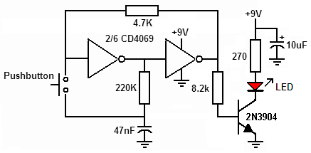
I recently found this circuit on the web :
![]()
This is an amazing solution to reduce the proliferation of buttons on the board, and save some space, and make it easier to route...
(of course, forget the useless 2N3904)
Edit: I also decided to drop the "blank" input. I wonder if this feature would be ever used, and it might be a bit confusing.
Furthermore I use 3 LVC1G08, it might be better to use HC08 instead (less crazy routing to the 3×2 power supply pins despite a larger package)
Or I could just use only NC7SZ157 (MUX2) to emulate AND gates. Too bad there is no quad MUX2 in DIP18. I have 74LVC157APWR but the select lines are shared so it's unsuitable for arbitrary logic :-/
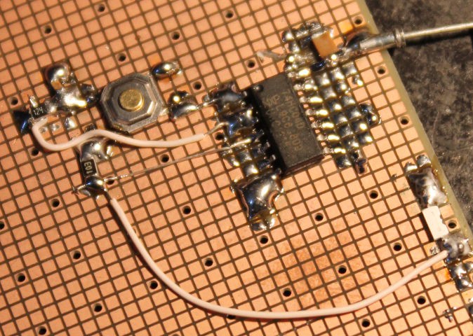
Edit: the above Flip Flop works.
I changed the feedback resistor to 10K and the the RC to 100K/100nF and it works nicely. However it is pretty sensitive to finger touches so the pads of the switches should be protected. But otherwise, it's a nice thing.
Only actual drawback: it's not easy to set/reset a latch as with the last method. So I only output one wire, that will be connected to 0V or +3V to force the state. This saves more wires (hence PCB surface and routing) and a couple of pins (one less pin after I removed the blanking input).
-
Alternate uses
01/26/2016 at 05:43 • 0 commentsDisplaying a bus value (address and/or data) is nice, but I have been suggested other uses, such as time display (think: clock) or multimeter display (volts, amperes, ohms, whatever). What else would you do with a DYPLED module ?
Edit (20160413)
The #SPDT16: 16-bits arithmetic unit with relays would need 3 or 4 #DYPLED
It would also be used in the #Quick & Dirty Frequency Generator to show the division factor and/or the actual frequency...
DYPLED
a thin LED display in SIP module format, much better than TIL311s to visualise your computer buses
 Yann Guidon / YGDES

 The right side is still not routed and I must triple-check that the logic on the left is correct. I'm so relieved I removed the SC70 MUX and a couple of other parts...