In the previous log I did very little explanation of how powder and inkjet printing (3DP) works. In this log I will give a brief explanation on 3DP in general, and then give an overview of what the Oasis project will and will not be.
3DP printing
3DP printing uses inkjet to print a binder into layers of powder. The binder is usually a fairly inert liquid (due to the nature of the HP inkjet heads) like water with alcohol. The powder is the material that needs to be printed (gypsum, ceramics, sand etc.) combined with a glue (Maltodextrin, PVA). Wherever the binder hits the powder, it locally melts the glue. Once the binder evaporates, the glue binds the powder particles together. Other combinations are possible, but this is the simplest version.
The 3DP printer provides an X/Y gantry for the inkjet printhead. It also has a (build) hopper with a piston that holds the powder. A system that distributes new powder into the build hopper is also required. A simple way is to have another (feed) hopper that holds the to be printed powder. A spreader is then used to spread a new layer of powder in the build hopper.
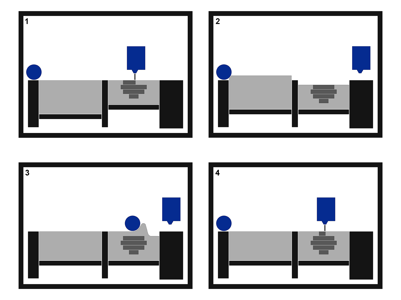
The order of operation for 3DP printing is as follows:
- The inkjet head deposits binder wherever the needs to be;
- The build piston lowers by the layer thickness, the feed piston raises enough to fill the build area;
- The spreader spreads the powder from the feed hopper to the build hopper;
- Go to step 1 and repeat until part is done.
After printing, the part can be removed and gently cleaned. The part can then either be used directly or processed to increase usefulness.
Oasis Mechanics
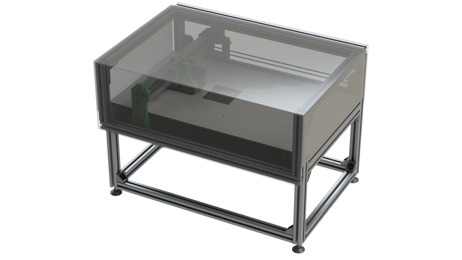
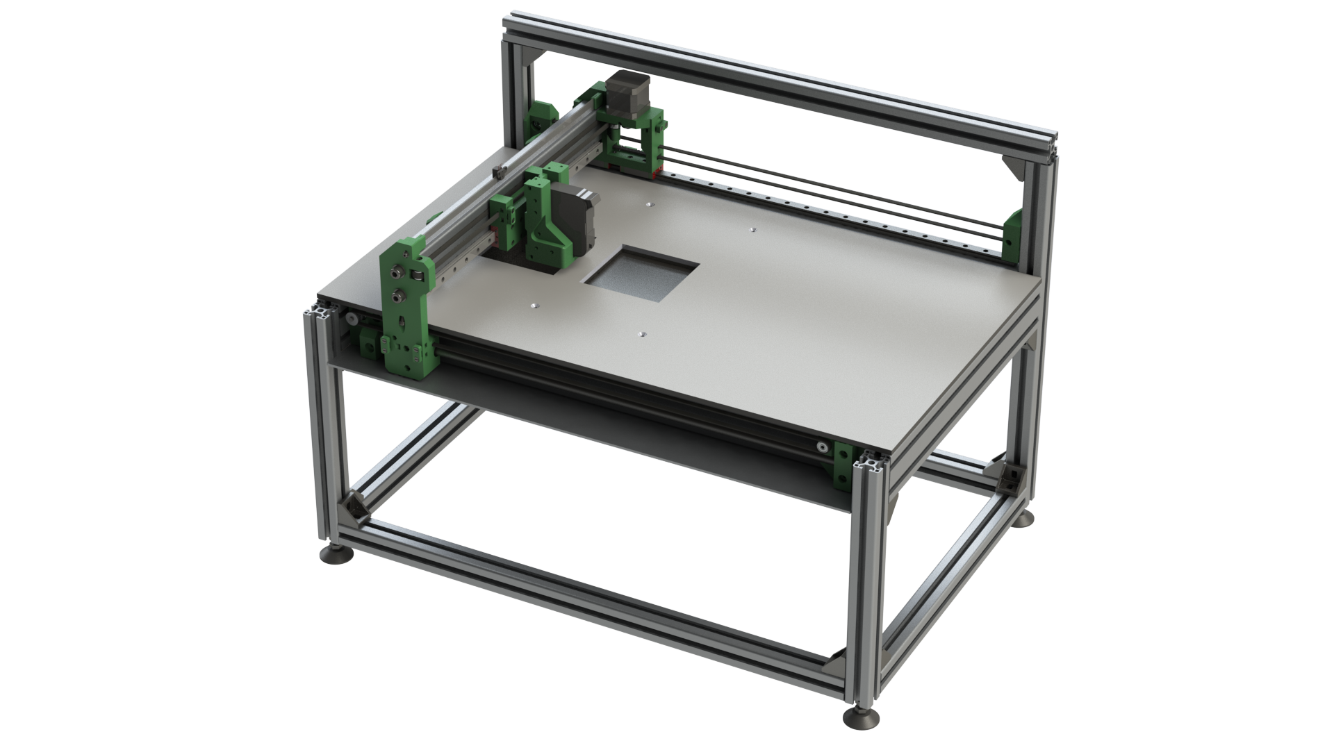
The first part of the project will be the Oasis printer. This is the mechanical build part of the project. The core will be an aluminium extrusion frame. The frame will house a removable build surface with two hoppers, and a gantry with the printhead. Also on the gantry will be the spreader and an optical encoder tape to synchronize the inkjet head with the motion controller. A raspberry pi will be at the heart of the printer, talking to both the motion controller and the inkjet controller. The motion controller will be an off the shelf GRBL controller using an Arduino Uno.
Below a few WIP images of the printer with and without cover. I will go over the details in future logs, when I am finishing parts, but most of the basics are there.
Inkjet controller
The inkjet controller will take care of all the inkjet related stuff. It will receive instructions from the raspberry pi. Motion and inkjet are separated because both are fairly resource intensive operations and inkjet is incredibly timing sensitive. A 10us mistake on the HP45 is enough to destroy a nozzle. The pi sends the inkjet lines with coordinates. The encoder on the printer is used by the inkjet controller to determine the position and print the right line at the right time. At this time both USB serial or SPI are considered. The teensy can do both at a high speed.
For more information on the HP45 itself, go to here. The summary is that the HP45 is a multiplexed array of FET's. 12V on the gate of the FET opens the channel. A ±2us pulse of 12V on the nozzle (called primitive) ejects a drop of ink from that nozzle. The printhead is common ground.
The inkjet controller will be built as a separate module with a Teensy microcontroller. Theoretically This means that it can also be used in different projects. However I will not focus on that. I have had 3 versions of this controller die to some degree of feature creep. This inkjet controller will initially only be programmed to be used on Oasis. As with the mechanical side, I will give more details on the specific components and design in future logs.
Printer control software
To control the printer a program with interface will be written in python. This software will interface with GRBL over USB serial, and the inkjet controller over either USB serial or SPI. The software will probably take slic3r svg files. The software will be the most difficult part for me. I am decent at programming, but I am at my core a mechanical engineer.
Software used
For this project I will use the following software:
- Solidworks 2014. I am sorry for anyone that uses Fusion 360. It is still something I want to learn in the future, but I will not let it be a constrain for this project. Step files will be provided where possible;
- KiCAD. For the PCB of the inkjet controller and maybe some other adapter boards;
- Arduino/Teensyduino for the inkjet controller software;
- Python for the software running on the Pi
Order of operations
For now the focus will mainly be on the electronics. I cannot finish the mechanical design nor the software without the electronics, and it is the only part that has a long lead time. After that the focus shifts to the mechanical side. Finishing the design and starting on the manufacture. This not because software will take less time, but mostly because I prefer to code while having a working machine.
Discussions
Become a Hackaday.io Member
Create an account to leave a comment. Already have an account? Log In.