The inkjet controller will be the first thing to work on. The PCB's will have a lead time of several weeks and other parts of this project interact with the controller. Also it is the one part that can be used separately in other projects. While I myself will not focus on that right now, I encourage others to try. Universal and open control of the HP45 would open a lot of opportunity for other projects.
Features and function of the HP45
First of a bit of information on the HP45. More of this info can also be found here, but a detailed summary:
The HP45 is an early 2000's (*citation needed) printhead, printing at 600DPI with 300 nozzles. The nozzles are arranged in 2 rows of 150 nozzles @ 300DPI, about 4mm apart and offset by 1/600th of an inch. This arrangement makes printing solid imaged more difficult, but probably is for manufacturing reasons. On several occasions I have simply printed with a single side to simplify printing.
The 300 nozzles are internally connected with a multiplexed array. Each nozzle is essentially a fet and a 30 ohm heater resistor, where the gate is rows (Address) and the input side is columns (primitives). The ground is common in the printhead. In total there are 22 addresses and 14 primitives, giving 308 possible combinations. 8 are unused.
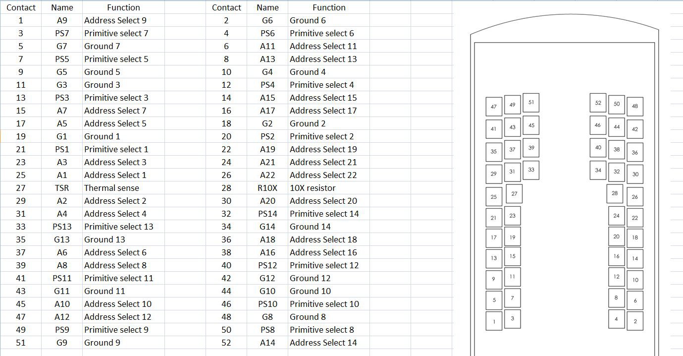
To connect to this matrix, the back of the printhead has 52 connection pads, again in 2 rows. 14 primitives, 22 addresses, 14 grounds and 2 feedback pins. A 10x resistor (10x, function a bit vague) and a thermal sense resistor (TSR). The address pads on each row connect to both sides of the nozzles. The primitive pads connect only to the same side of the printhead.
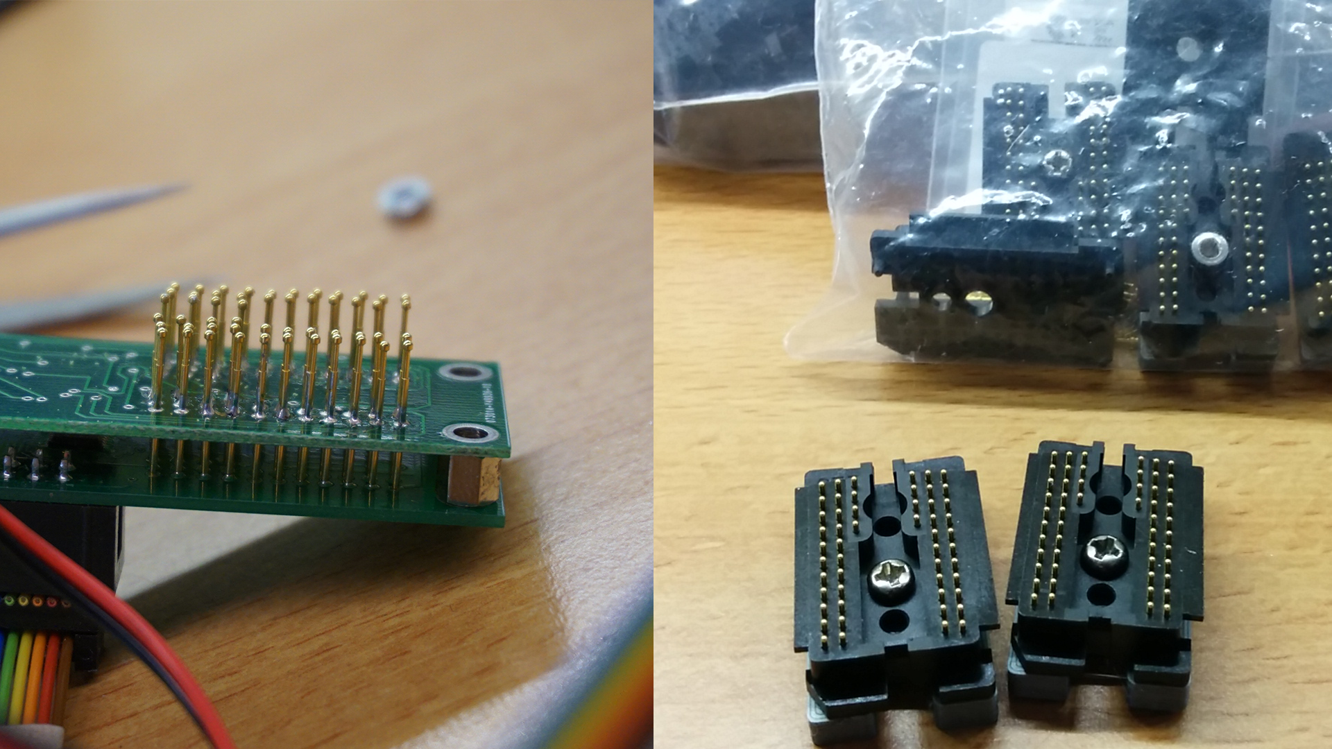
There are 2 ways of connecting to the pads of the HP45. One is an array of 52 miniature pogo pins soldered on a PCB. I did this for a while, but it is fragile and tedious. The other is an HP45 connector. I had to buy them in bulk, and they are spendy, but they are very robust (still tedious though).
To fire a nozzle, first the address must be powered with 12V. This opens the gate of the fet. After a microsecond or so, the primitive can be powered with a high side 12V for about 1.8 microseconds. Exact time can vary by a few hundred nanoseconds. After this time, the primitive can be closed, and a microseconds or two later the address can be closed and the next can be opened. Especially the primitive is challenging, because it is high side and the timing is critical. Most components either do the high side, or do it in a few hundred nanoseconds, but few do both. Officially the voltage for primitives is not exactly 12V, but 9-13V. The printhead is supposed to test it's own ideal temperature. I have not successfully implemented this yet, and will not on this controller. The 12V may reduce lifetime, but it is an order of magnitude simpler to make.
To get temperature back, there are 2 more pads on the head called 10x and TSR. 10x is a bit of a mystery, but probably some calibrated part in the head that is 10x the resistance of the nozzle (10x 30, seems about right at 300 ohm). The TSR is a resistor is also around 300 ohms and rises 11 ohm per 10 degrees. There is some more relation to the 10x resistor, but that is the basics. The TSR also sits really close to the nozzles, responding almost instantly to the nozzles firing or preheating.
Schematic
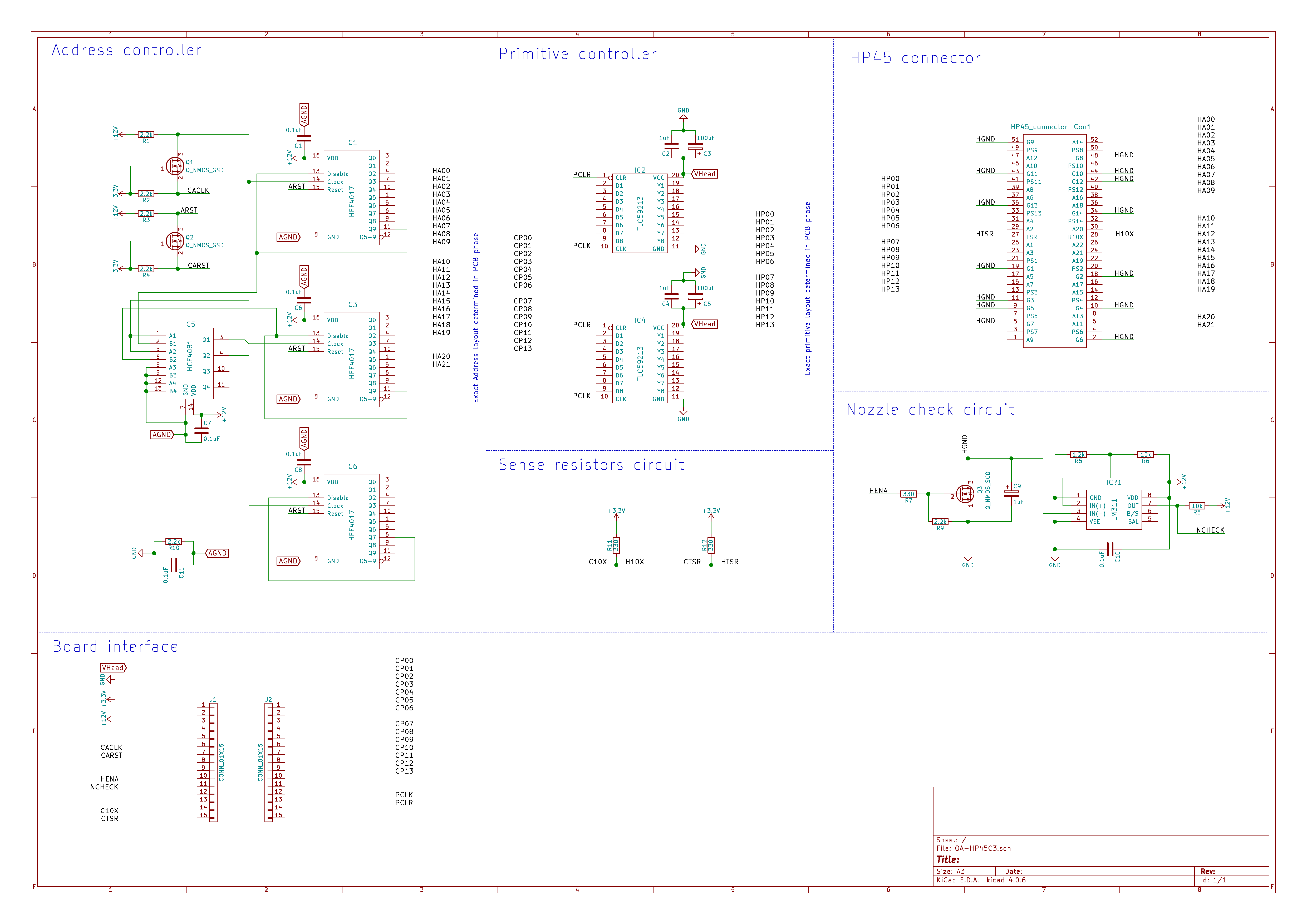
This is the schematic so far. Most complex routing is still not done. This is done while making the PCB. Most routing is not really dependent on the exact pin. Also missing is the controller board. I will keep the microcontroller in the form of a Teensy on a separate board, for several reasons. The most important reason being that Teensy's take a huge amount of PCB space. (And I do want to use a Teensy, for personal preference reasons).
Address circuit
The address circuit is at it's core a series of 4017 decade counters on 12V. The 12V required on the addresses is only voltage, no current, so most driving chips are out of the question. The 4017 have a decent pulldown resistor so they drop to 0V quick enough. The 4081 is used to lace the 4017's together. After a reset, each pulse of the clock pin will advance to the next address until the last address is reached. After that the circuit will disable until the next reset. This circuit will never have 2 addresses high at the same time. To make the 3.3V microcontroller talk to this circuit, 2 mosfet level shifters are used.
A weird thing in this address block is the resistor on the ground. This exists for the nozzle check circuit. The roughly 1-5k resistor to ground on each address in the 4017 and in the printhead drain all power while testing a nozzle, dropping the voltage to unusable levels. The resistor is a hack that raises the overall address resistance to usable levels.
Primitive circuit
The primitive circuit uses TLC59213 chips. These are high side driver chips that open and close in 250ns. Also they can provide the 0.4A per nozzle required. Another handy feature is the latch. I do not need a microcontroller that can set all 14 pins at once, I can set them one at a time if required, and then latch the pins.
The 0.4A is theoretical, but there is a problem. When all 14 primitives are firing at once, not all will fire. I have tried fixing this with more TLC chips (with 2 driver pins per primitive) but this did not fix the problem. The solution so far has been to fire the nozzles in groups of 5, 5 and 4. This is also the reason why the images in one of the handheld test look damaged. I think I am doing something wrong elsewhere but for now I will not fix this.
Nozzle check circuit
The check circuit consists of a mosfet on the HP45 ground, a capacitor and a 311 comparator. To test a nozzle, the capacitor is drained first by opening the fet. Then the fet is closed and short pulses are given on the to be tested nozzle. If the voltage rises before a certain amount of pulses, the nozzle is good. If after an amount of pulses the voltage is still too low (like 20). the nozzle is considered broken.
A wiser person would use a constant current source, and it is done this way more often, but I have not yet had experience with constant current sources and I am not going to try right now. This way works surprisingly well, and the constant current source is added to the list of future improvements.
Temperature feedback
Both 10x and TSR are by default around 300 ohms. To measure them, I could use the same constant current source I do not have to get the resistance. Instead, I use a simple voltage divider to get the resistances. One thing to keep in mind is to always open the mosfet on the printhead ground before measuring. Else you will not get anything.
Headers to controller board
On the board are 2 rows of headers. These are for mounting the controller to the driver board. I will make and discuss the controller board in a later log. The separation is for size, flexibility and future improvements with multiple heads.
Discussions
Become a Hackaday.io Member
Create an account to leave a comment. Already have an account? Log In.
Hey. How about leaving the inkjet printer mostly intact? Mount it on rails. Interface with its encoder. That would give you a multiple color much higher res printer. What are you using to slice the object into separate images to print?
Are you sure? yes | no
For a shortest path to reach any form of inkjet, the path you describe is valid indeed. The reason I chose to do it the hard way is that modifying an existing machine has more limited future potential. It is hard to replicate, limited in what you can actually control and subject to change as drivers are changed. I have pixel for pixel, shot for shot control of the printhead. I can scale it to whatever size I want, not limited to the standard drivers, and I can easily make 20 controller behave exactly the same way. The amount of work beforehand is indeed much more, but the options when the project is done are much broader.
So far I am using SVG files from Slic3r. These parse easily into a printable images. The software side is a bit of a weakspot for this project though.
Are you sure? yes | no
you should make a YouTube channel, bet This kind of projects would get a lot of views
Are you sure? yes | no