I would add this to the instructions as well, but Hackaday.io is a bit special in that it wants me to edit ALL instructions at the same time.
Someone made a mistake on the driver board V3.01 (it was me). The pullup for the nozzle check signal is pulled to 12V, not 3.3V. This means that an input for the Teensy is being pulled to 12V most of the time. I myself have not experienced any issues whatsoever with this, but I suspect some other people I have been talking to have experienced issues (broken Teensy's).
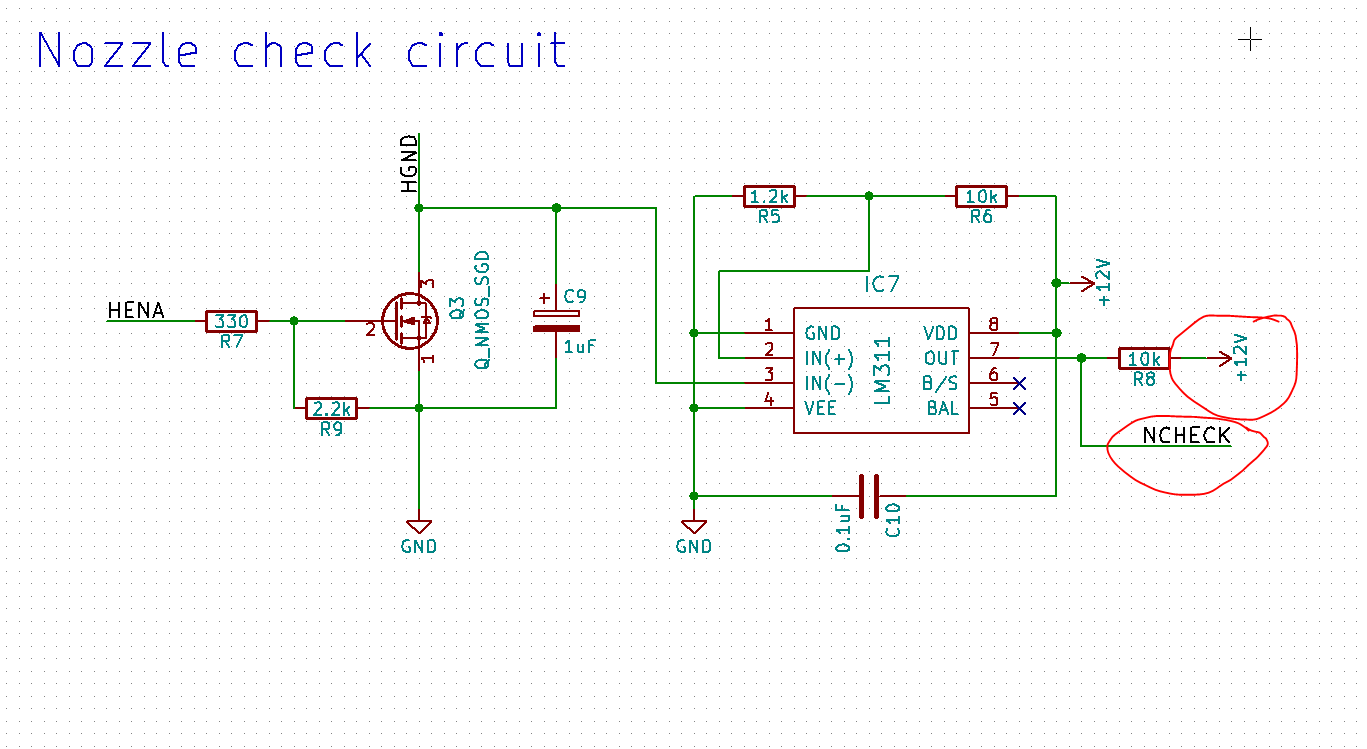
However this new design will not fix the problem for people who already have a board. Below is a fix for this issue. TL;DR is tombstone the resistor and solder a wire to the nearest 3.3V.
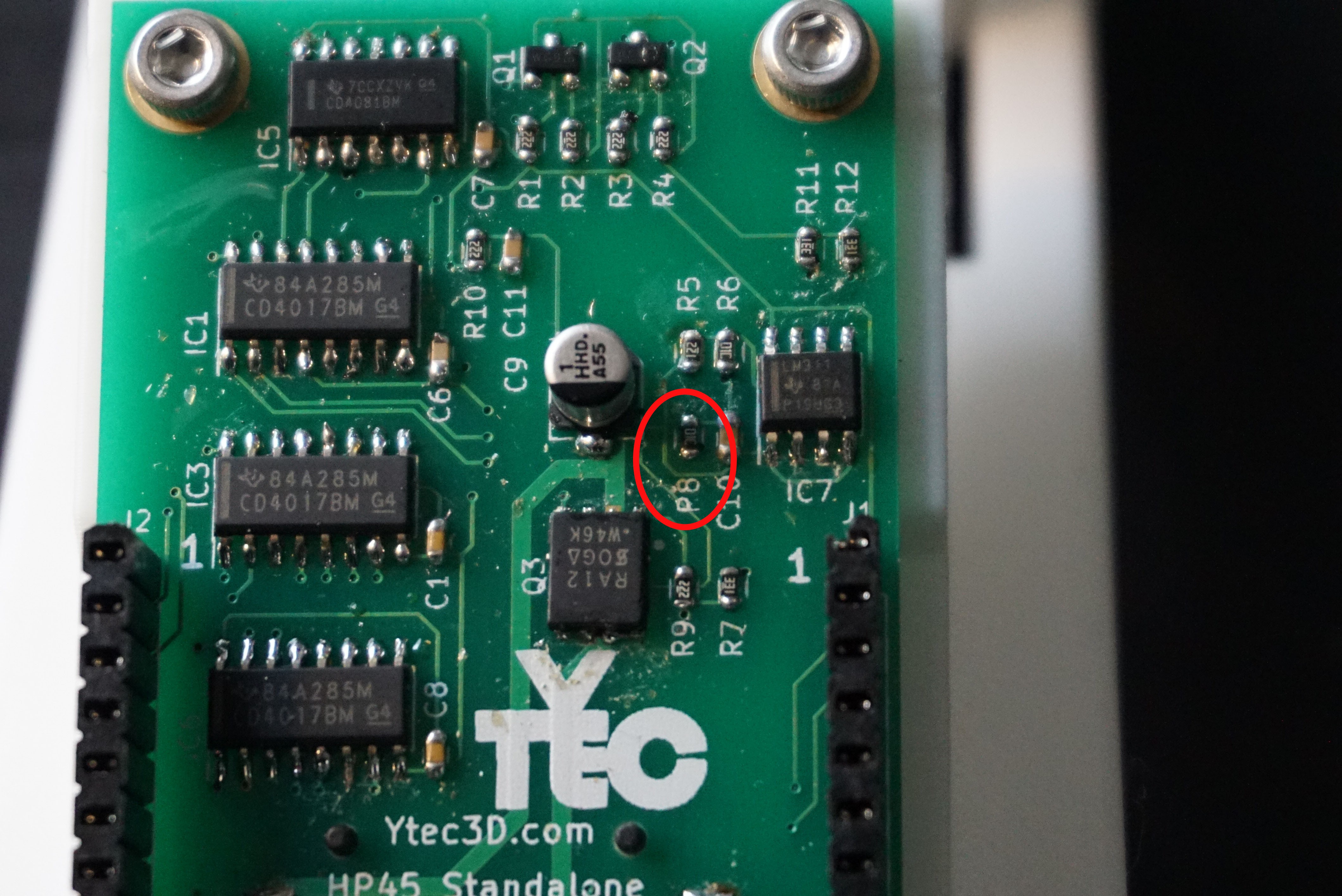
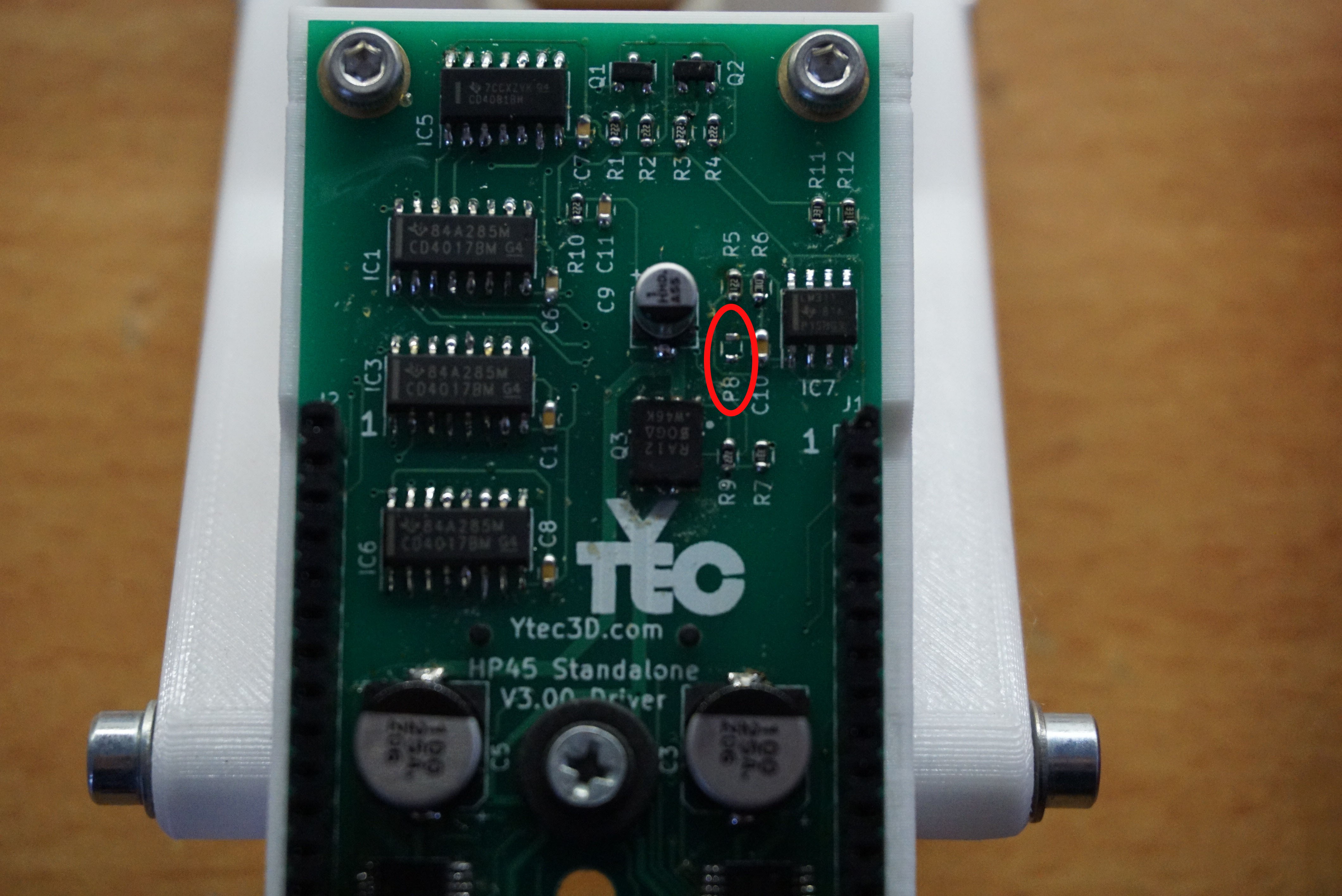
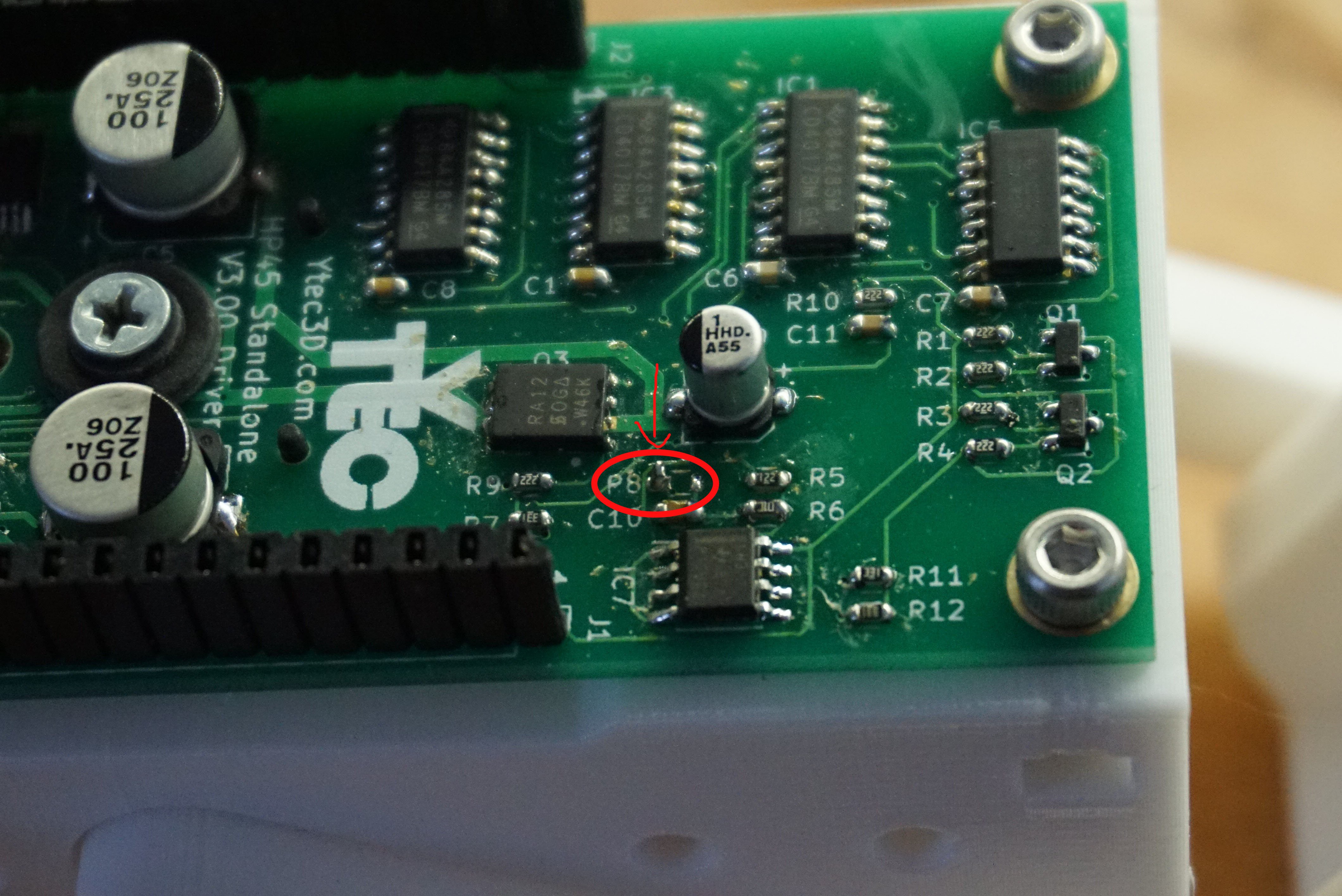
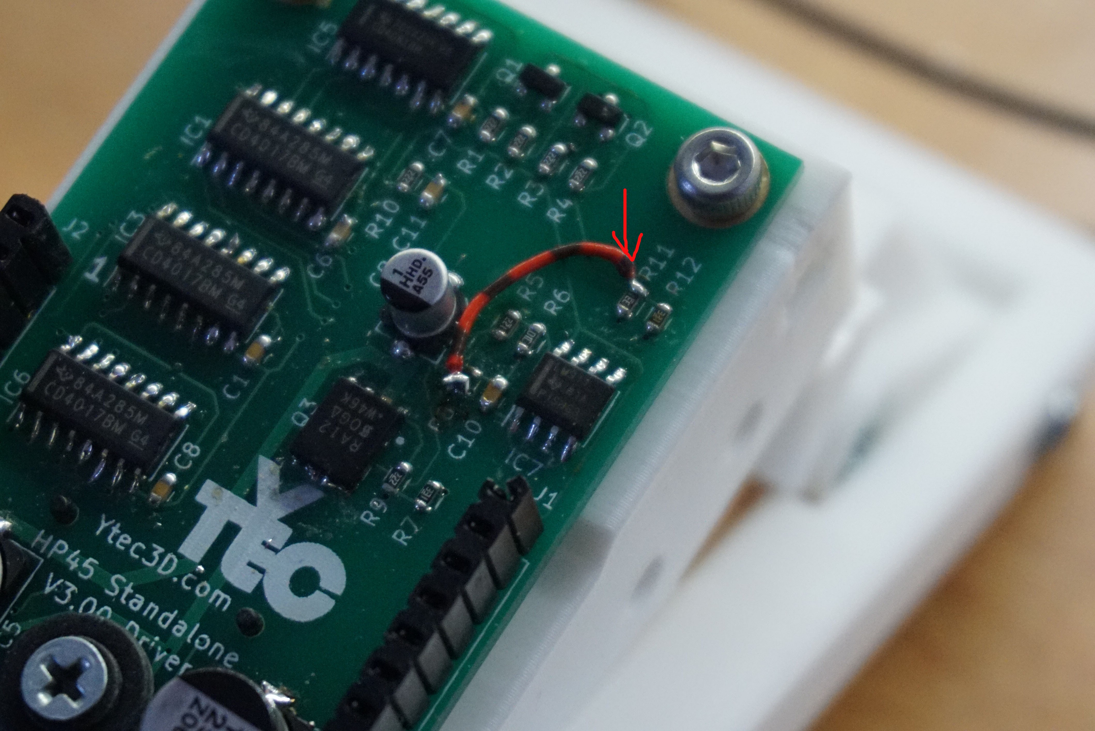 Now the check pin is pulled to 3.3V and the check pin is no longer capable of destroying the Teensy.
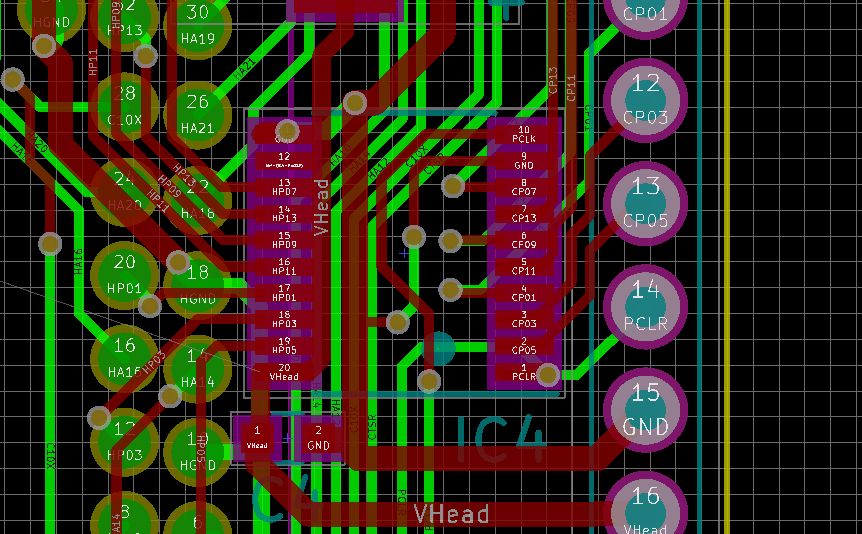
(Edit 20 minutes later: While designing V3.02 I found an even bigger mistake in the PCB on the TLC driver. It shorts 12V to ground, and several signals directly to ground. It is not in the Gerber files (V3.01 still had V3.00gerber files in it) but it is in all versions of the KiCAD files. The TLC driver has moved 2mm to the side and shorted on everything. I will fix and upload ASAP because this is a real problem. I have no clue how this one got in, but it is quite a bad one. My apologies)
Discussions
Become a Hackaday.io Member
Create an account to leave a comment. Already have an account? Log In.