-
1Before you start assembling
You want to build an Oasis. Neat. Be aware that it is a prototype and not a finished, optimized product. Toolchain, Software and firmware still needs to be optimized. Why is there documentation if it is not finished. Because it works.
All the most up to date files for Oasis are here, in the file section of the Hackaday.io page. To make an Oasis you will need 3 files the most. The first is an excel file called 'Oasis total BOM *date*'. This contains the full Bill of Materials for Oasis, mechanical and electrical. The second is 'OA-Y00-A01-00 3D-PDF *date*' This is a 3D PDF of the mechanical build of Oasis. This should help aid in the building of Oasis. The last is a zip file 'Oasis make package *date*' This contains all files and drawings to make an Oasis.
After extracting you will see 4 folders. 'Electronics', 'Firmware', 'mechanical', and 'software'. Each folder contains all necessary files to make an Oasis for that category.
In 'Mechanical' There is a certain file structure in the names. All custom parts and assemblies have the name: 'OA-Ynn-Ann-nn' or 'OA-Ynn-Pnn-nn', where 'n' is a number. 'OA' is the project (Oasis), 'Ynn' is the group, or subassembly. 'Pnn' is a part, 'Ann' is an assembly, and the last 'nn' is the revision. The project starts at 'OA-Y00-A01-00' (as of writing. If you see a higher revision, don't worry and pick that). This contains the full drawing of the assembly, and refers to other subassemblies and parts.
In each subfolder you will find at least one PDF drawing of that subassembly, PDF drawings of parts you might need to make, and STL files of parts you need to print. All drawings and step files are accompanied with STEP files you can open in many CAD packages for reference or to change them.
These drawings, accompanied with the 3D PDF, should help you assemble the mechanicals of Oasis.
Now the bad news. I do not have a full set of photos in the order of assembly. I built what is in the files over 3 months, improving parts as I built. In my drawings, I tried to give a good suggestion for order, but the photo's will not follow that. If you want to assemble it in your own order, feel free. All the the provided photo's are for reference and not in chronological order at all. Nonetheless I hope they will be useful.
-
2Assembling electronics
The electronics can be installed afterwards, but in order to keep this guide as chronological as possible, it is first time to assemble the electronics. In the BOM, under 'Electrical' you will find a list of components, including what name they have on the PCB, and the footprint. I will be hand soldering SMD in this example, so it might be a bit messy in places.
HP45 driver board
The first board and the most complex board is the driver. This driver board controls all addresses, primitives and has the ability to test the nozzles.
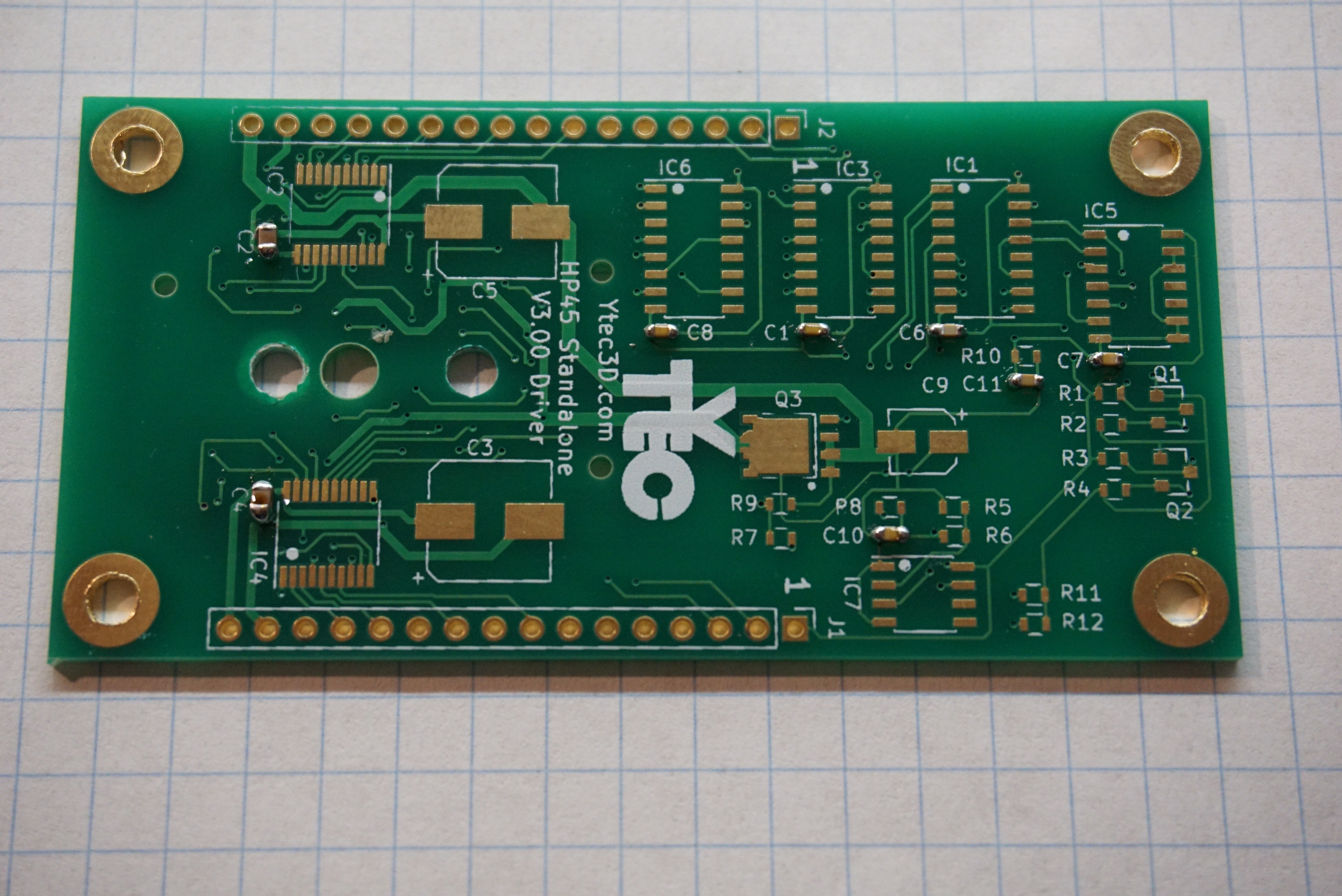
Install the capacitors. The footprint of the capacitors is 0603 and they should be at least 16V. C1, C6, C7, C8, C10, C11 are 0.1uF, C2, C4 are 1uF. Polarity does not matter on these capacitors.
![]()
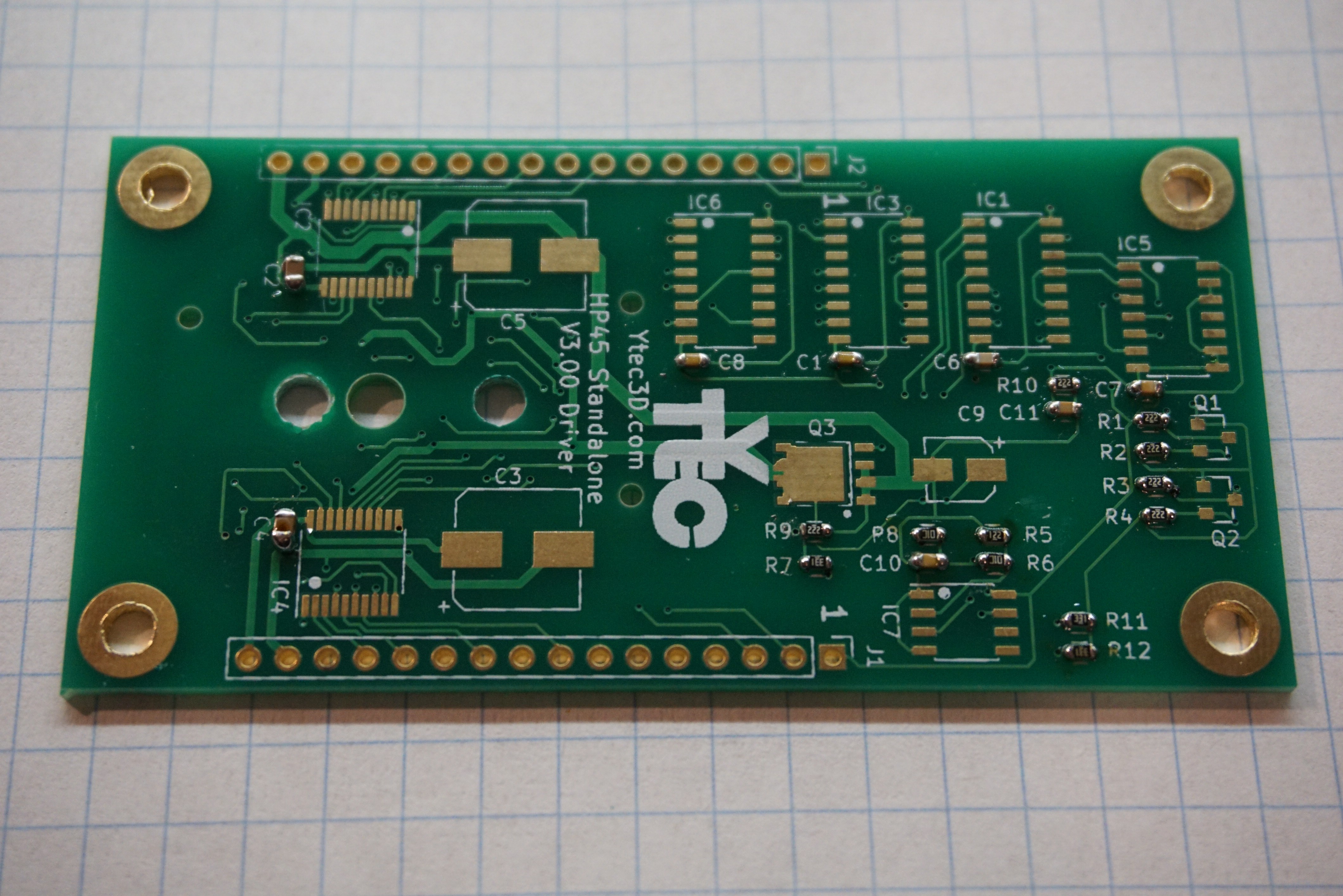
Install the resistors. The footprint of all resistors is 0603, they should be 1% and need to be around 0.1W. R7, R11, R12 are 330Ω, R5 is 1.2kΩ, R1, R2, R3, R4, R9, R10 are 2.2kΩ and R6, R8 are 10kΩ.![]() Install the mosfets. There are several types. Q1 and Q2 are the small ones. They are PMV20CNER and have a SOT-23 footprint. They only serve to shift level, so any low threshold voltage N channel mosfet should work. Q3 is the big one. It is a SIRA12DP-T1-GE3 in an SO-8 power pack. It needs low on resistance and a gate voltage lower than 3V. The dot marks the orientation for Q3.
Install the mosfets. There are several types. Q1 and Q2 are the small ones. They are PMV20CNER and have a SOT-23 footprint. They only serve to shift level, so any low threshold voltage N channel mosfet should work. Q3 is the big one. It is a SIRA12DP-T1-GE3 in an SO-8 power pack. It needs low on resistance and a gate voltage lower than 3V. The dot marks the orientation for Q3. ![]()
The IC's are plentiful on the driver board. IC1, IC3, IC6 are HEF4017 with package SOIC-16 3.9mm. The exact 4017 is not important, only that it is at least 15V. IC5 is HCF4081, the package SOIC-14 3.9mm. Again, only voltage is important. IC2, IC4 are TLC59213. Rhese will be most difficult to solder. The package is TSSOP-20. Foot pitch is 0.65mm. The last component is C7, LM311. It is SOIC-8. On all components there are dots and marks to indicate orientation.![]() Install the Electrolytic capacitors. C3, C5 are 100uF, 16V minimum, package 8mm, height lower than 10mm. C9 is 1uF, 16V minimum, package 4mm.
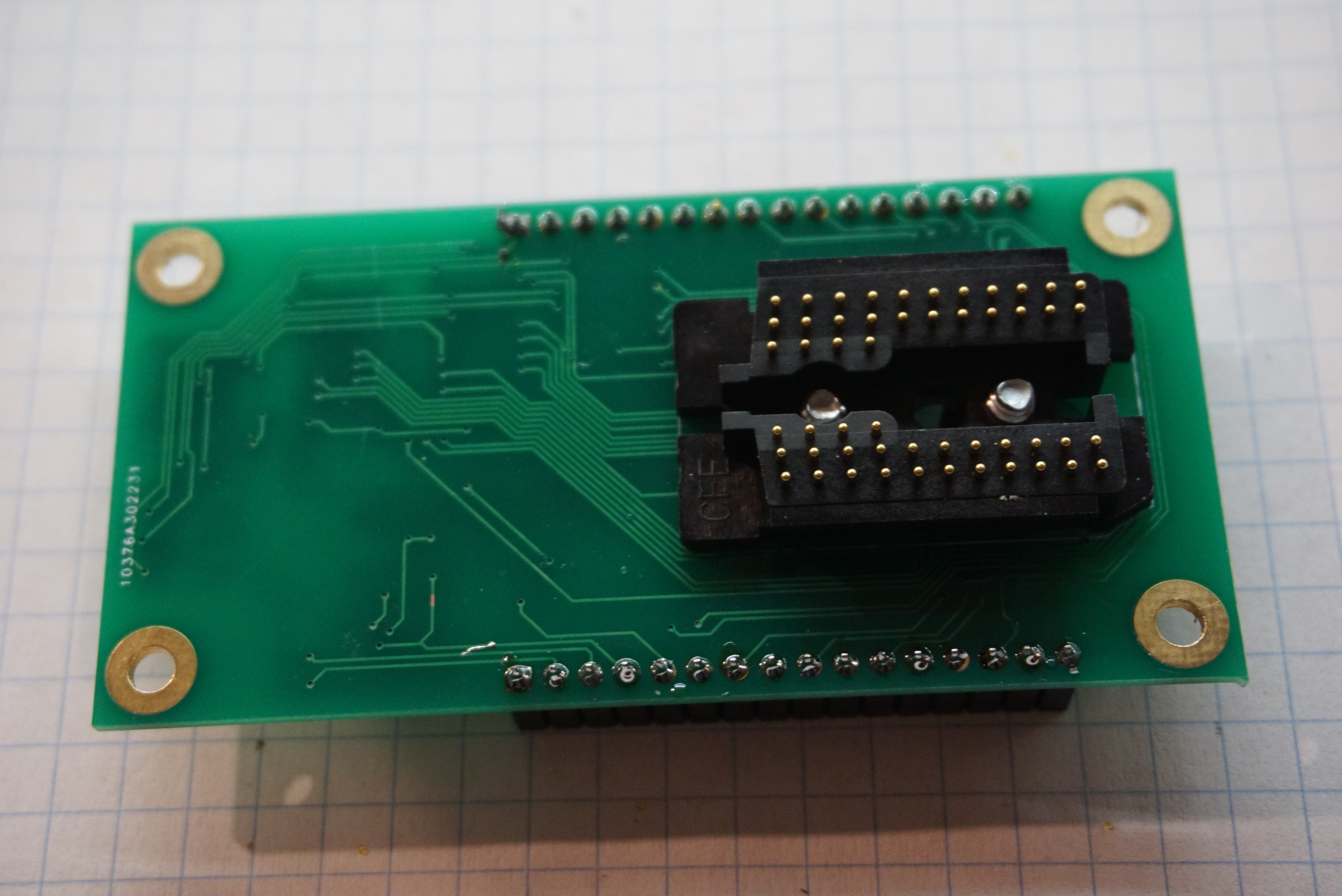
Install the Electrolytic capacitors. C3, C5 are 100uF, 16V minimum, package 8mm, height lower than 10mm. C9 is 1uF, 16V minimum, package 4mm.![]() Mount the HP45 connector using M3x6 or #6 screws (I am experimenting with #6, if they behave I will include them in what I sell. The holes are not actually big enough for #6, so I do have to ream the holes right now.
Mount the HP45 connector using M3x6 or #6 screws (I am experimenting with #6, if they behave I will include them in what I sell. The holes are not actually big enough for #6, so I do have to ream the holes right now.![]() 2x 16 pin female headers, 2.54mm (J1, J2)
2x 16 pin female headers, 2.54mm (J1, J2)![]()
![]()
HP45 controller board
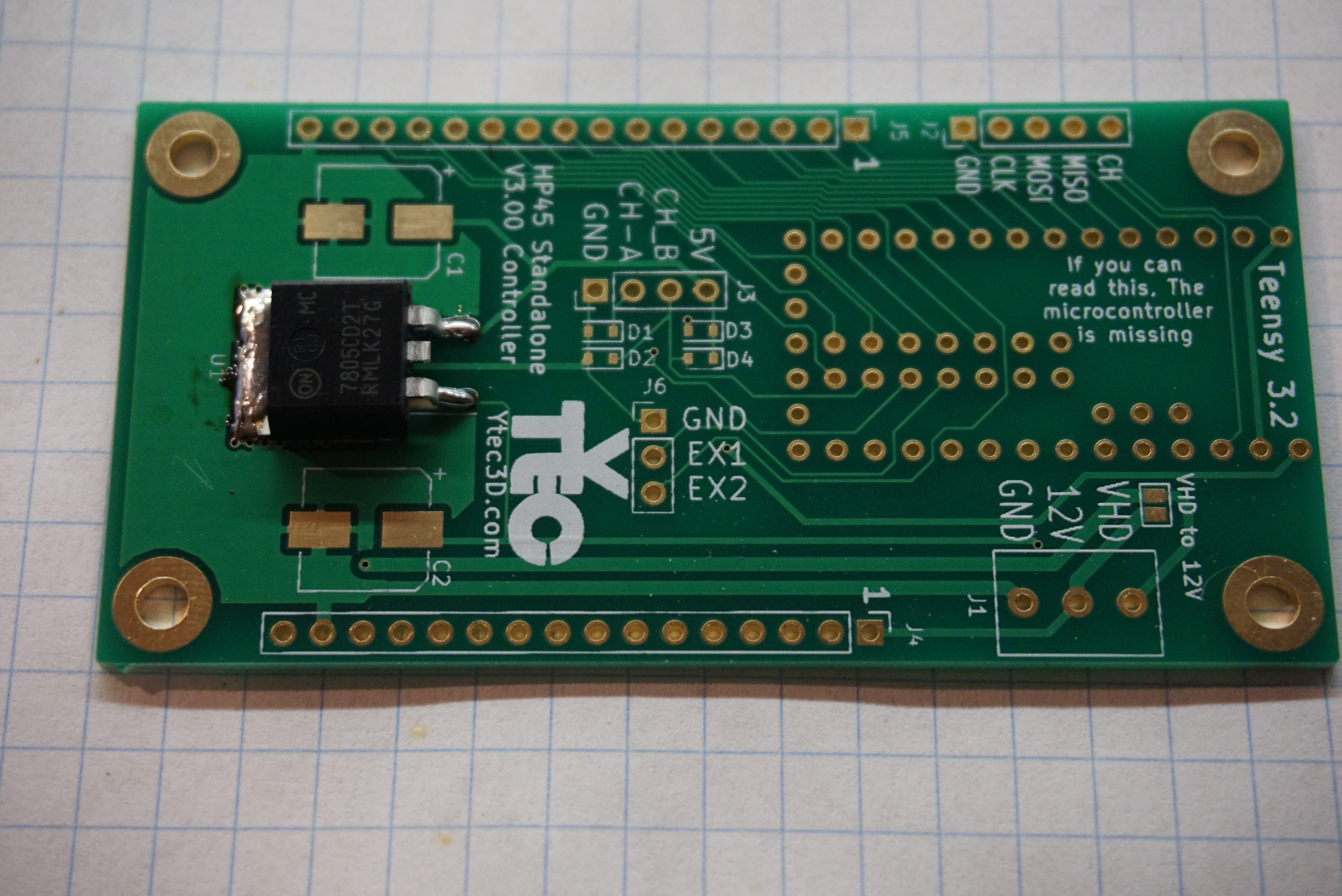
Mount the U1 7805 voltage regulator, footprint TO263-2.
![]()
Place the Teensy 3.2 on the controller to align the male headers. Solder a few of the pins on the Teensy (But NOT on the PCB) to secure the headers. You'll need 2x 1x14, 1x 1x5 and 1x 1x3.![]()
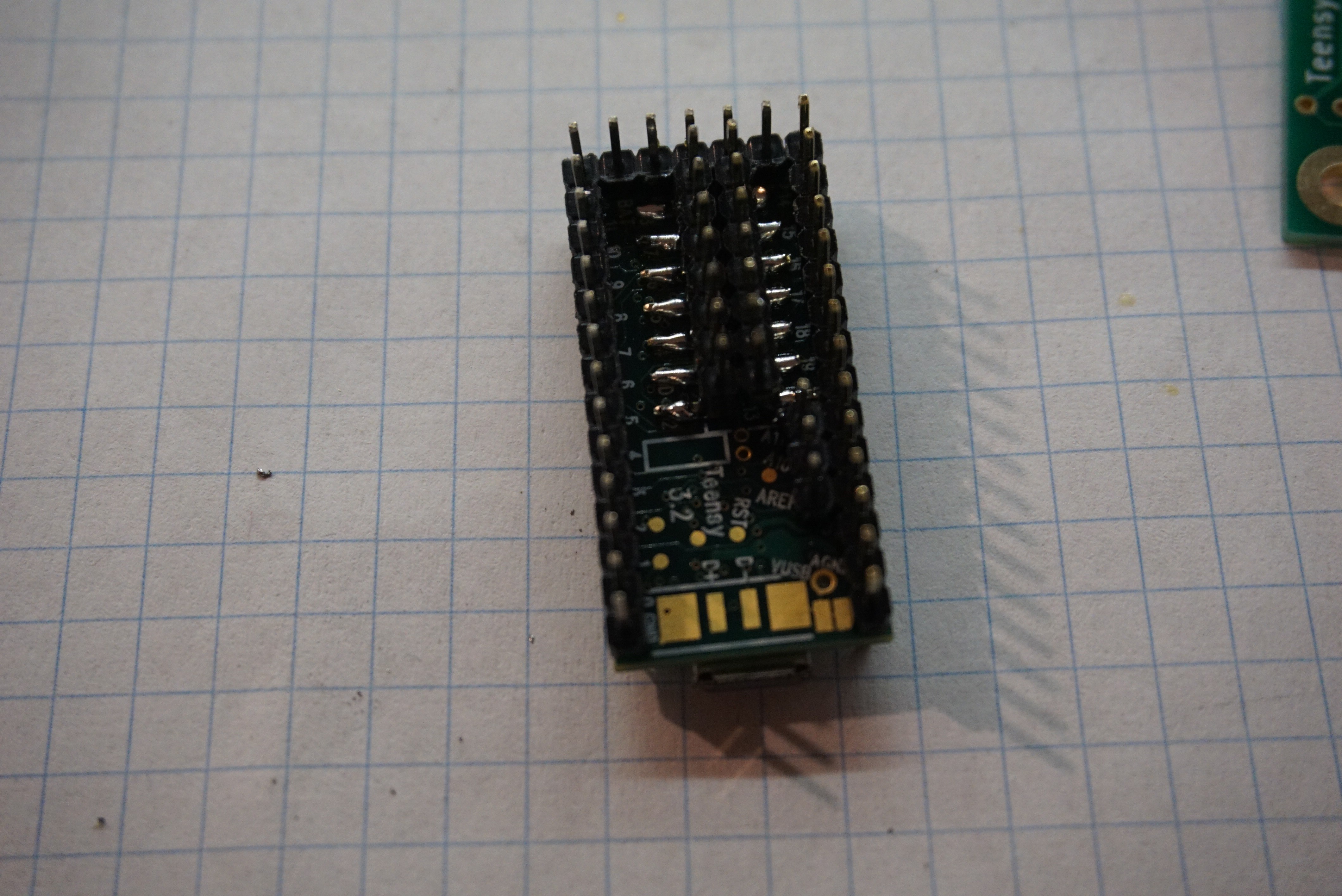
Solder SMD male header 2x7 (or 2x 1x7) under the Teensy 3.2. Make sure it is aligned with other headers. Make sure all SMD pads under teensy make good connection to the Teensy if you permanently solder it in place. Once it is in place, you cannot access it to repair a solder joint.
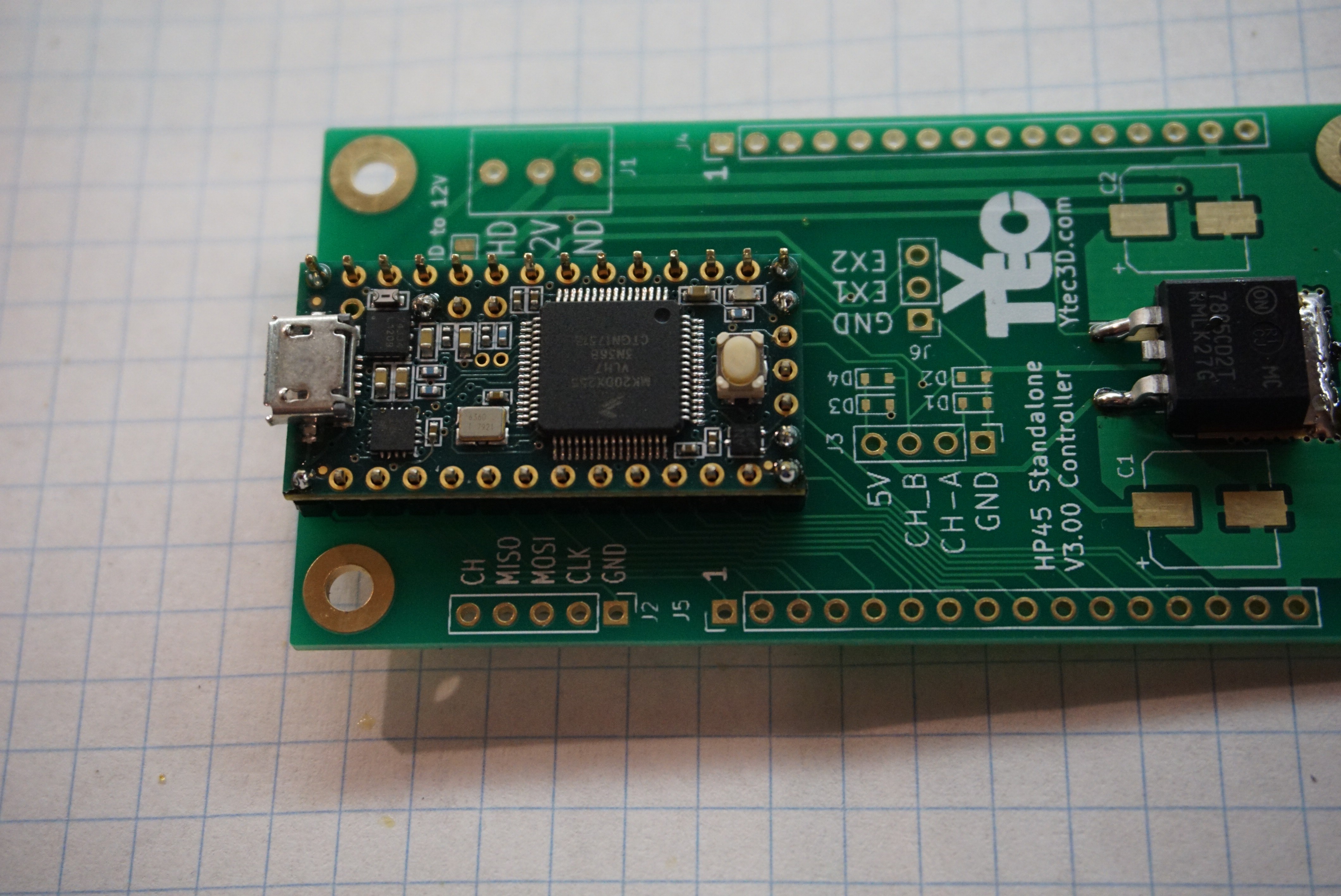
![]() Solder the Teensy 3.2 to controller board. Here you can optionally solder female headers to the board. Be aware though that this will increase the height of the whole assembly to a point where it will not properly fit in Oasis.
Solder the Teensy 3.2 to controller board. Here you can optionally solder female headers to the board. Be aware though that this will increase the height of the whole assembly to a point where it will not properly fit in Oasis.![]()
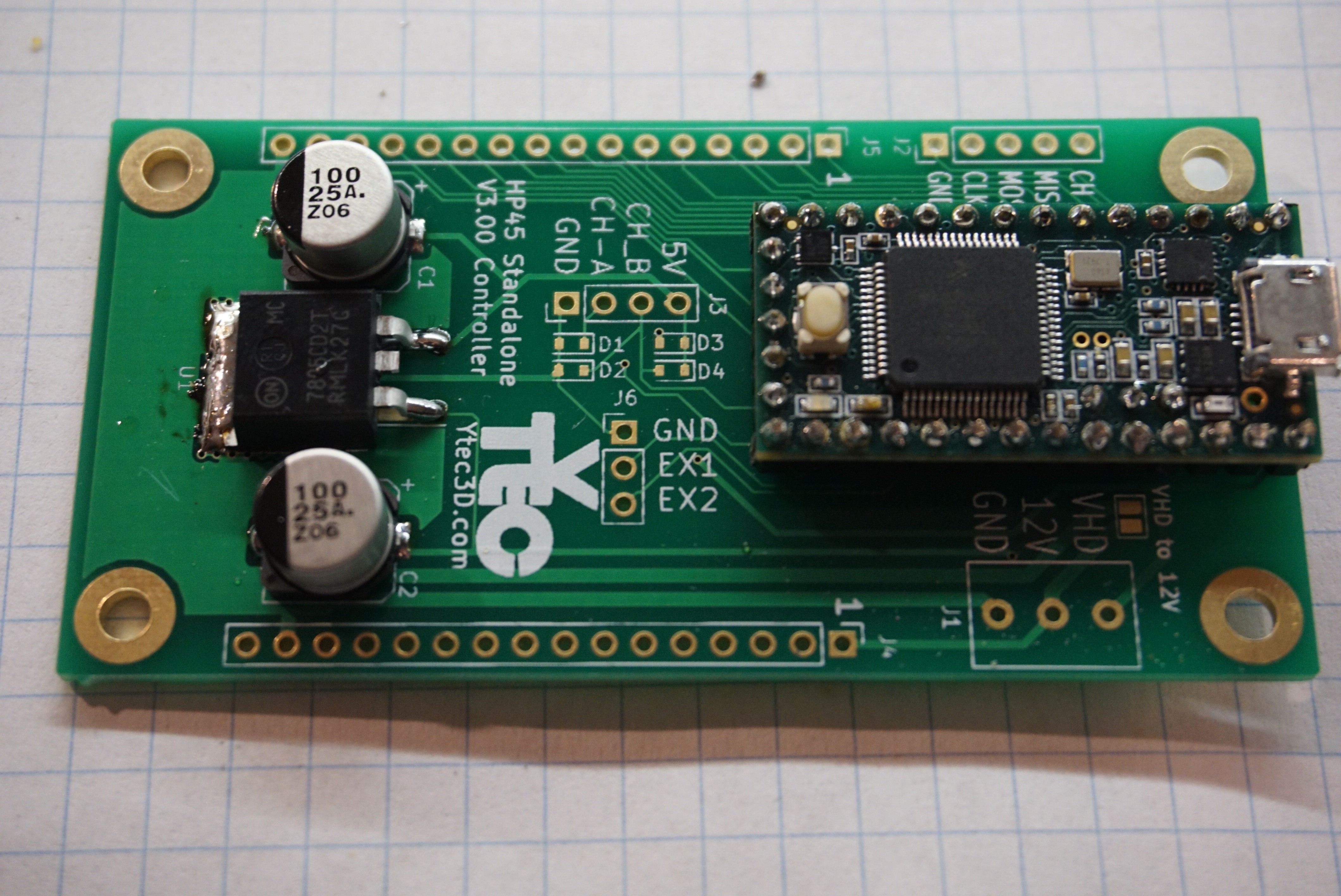
Solder the electrolytic capacitors C1, C2. 100uF, 16V min, package 8mm.
![]()
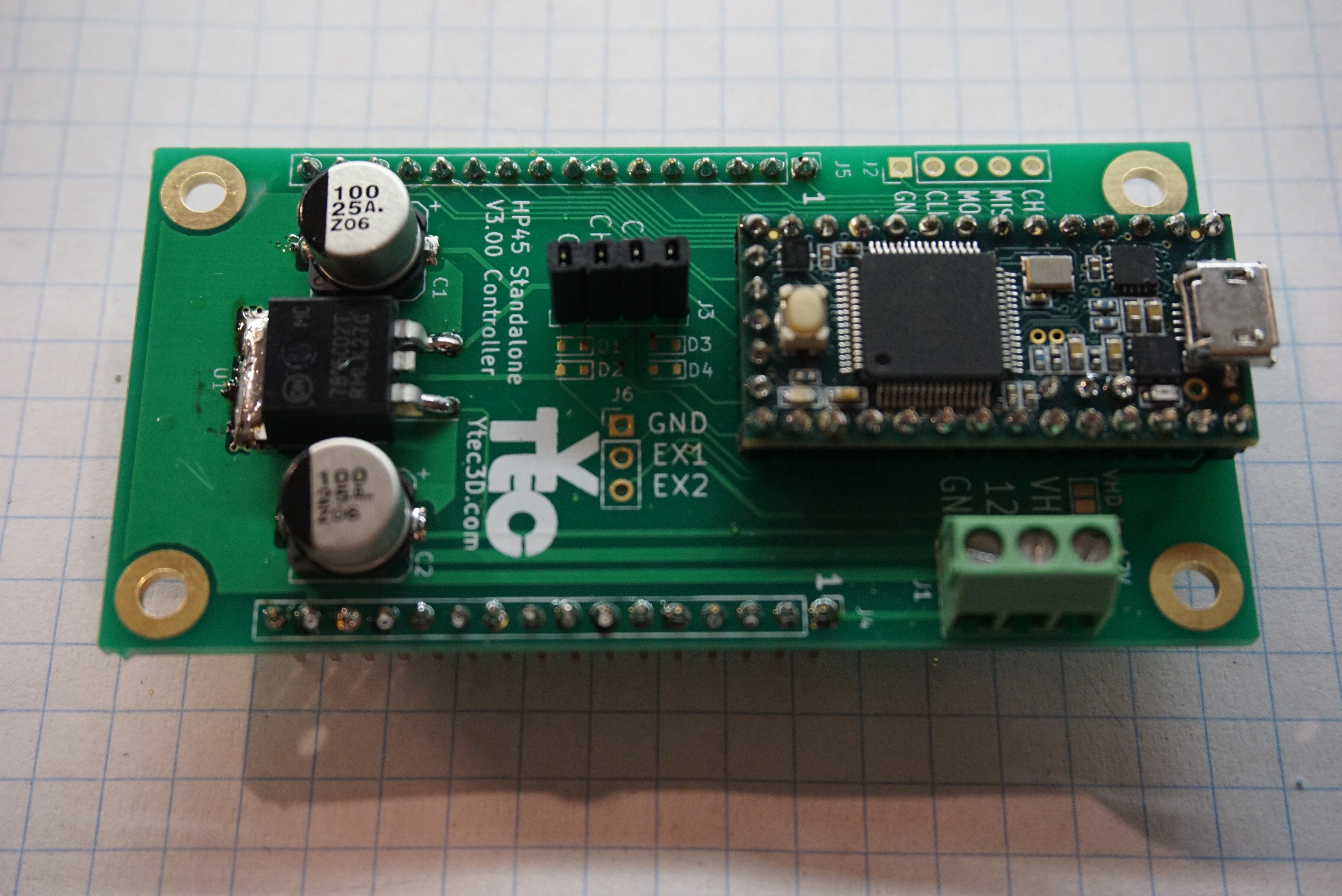
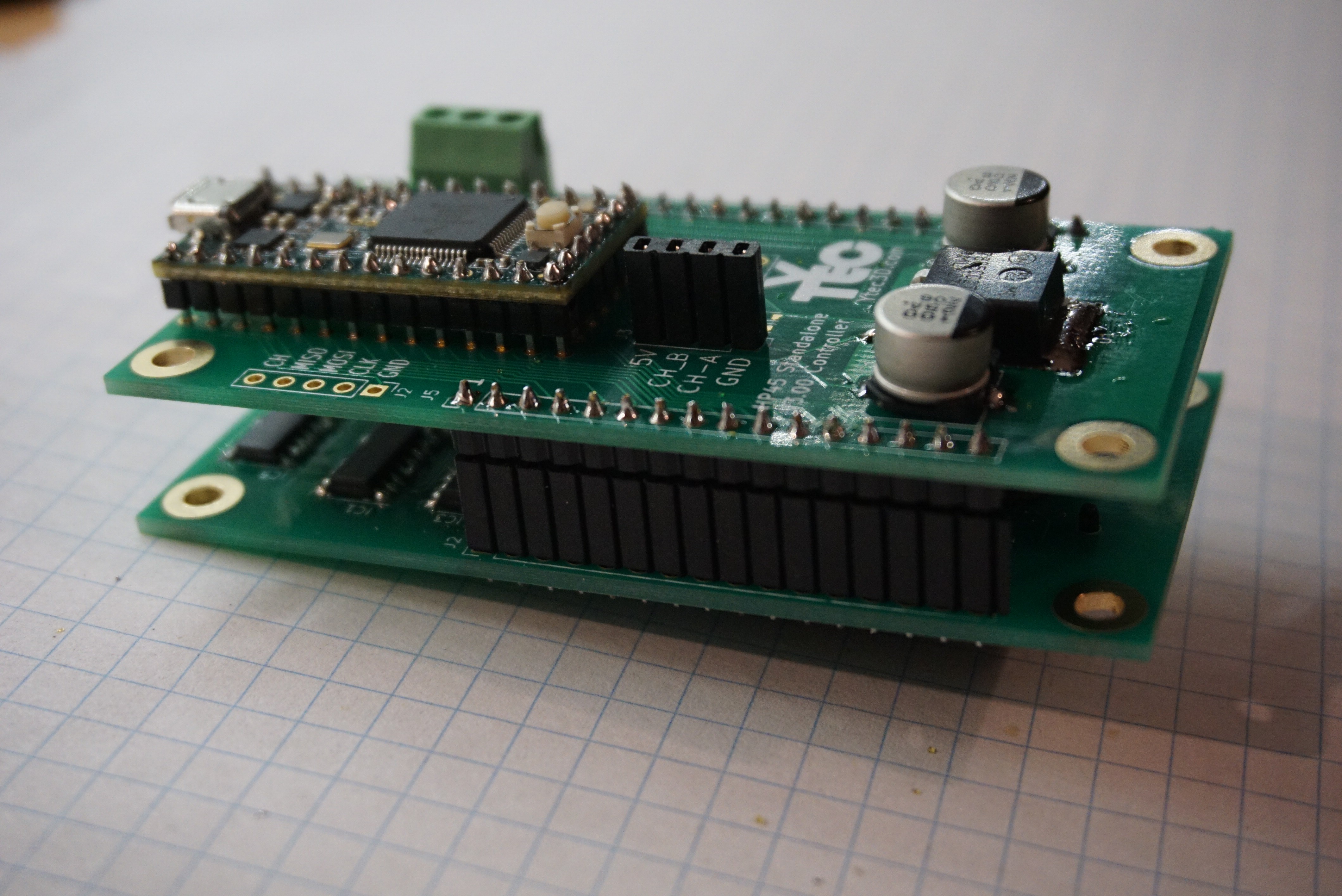
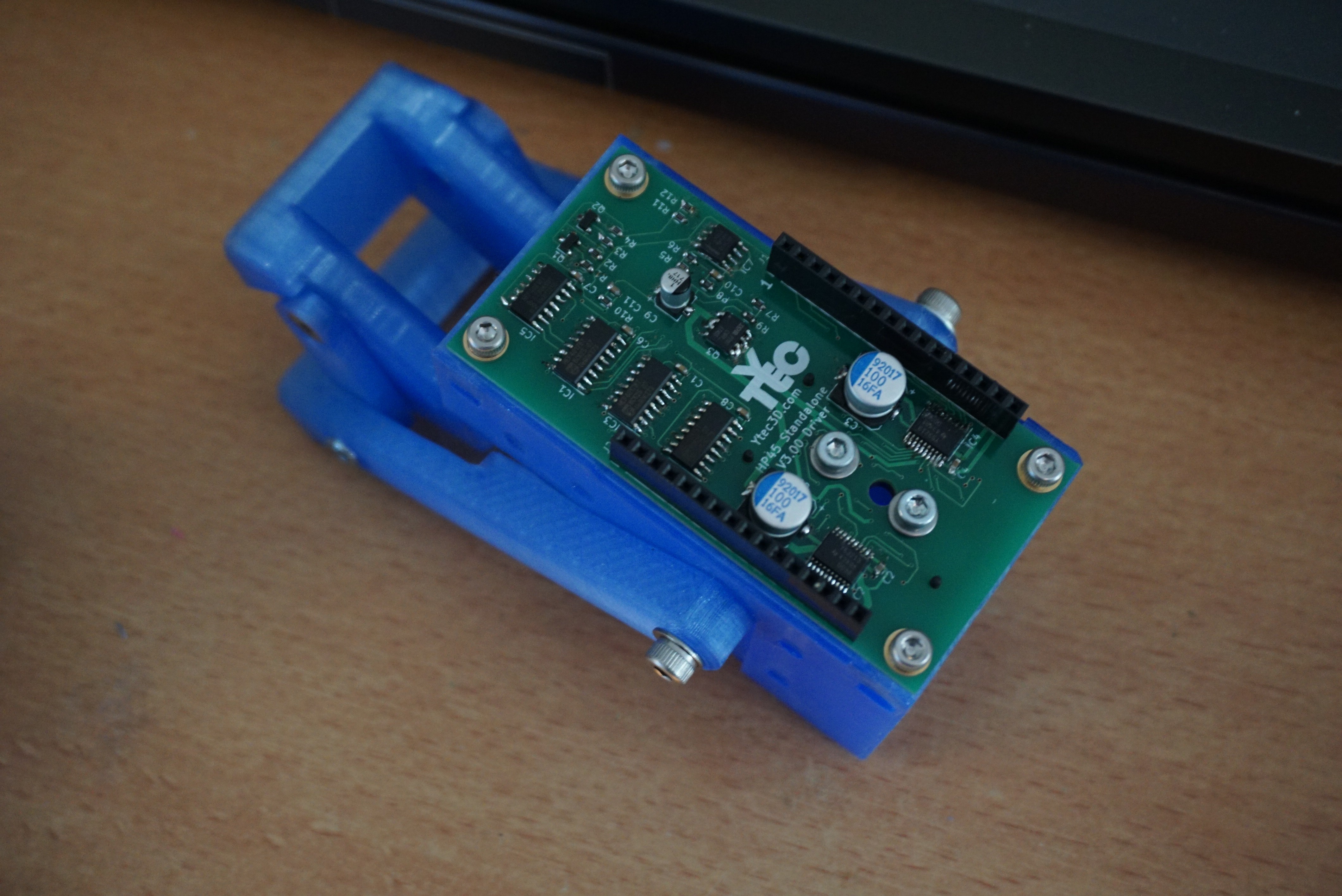
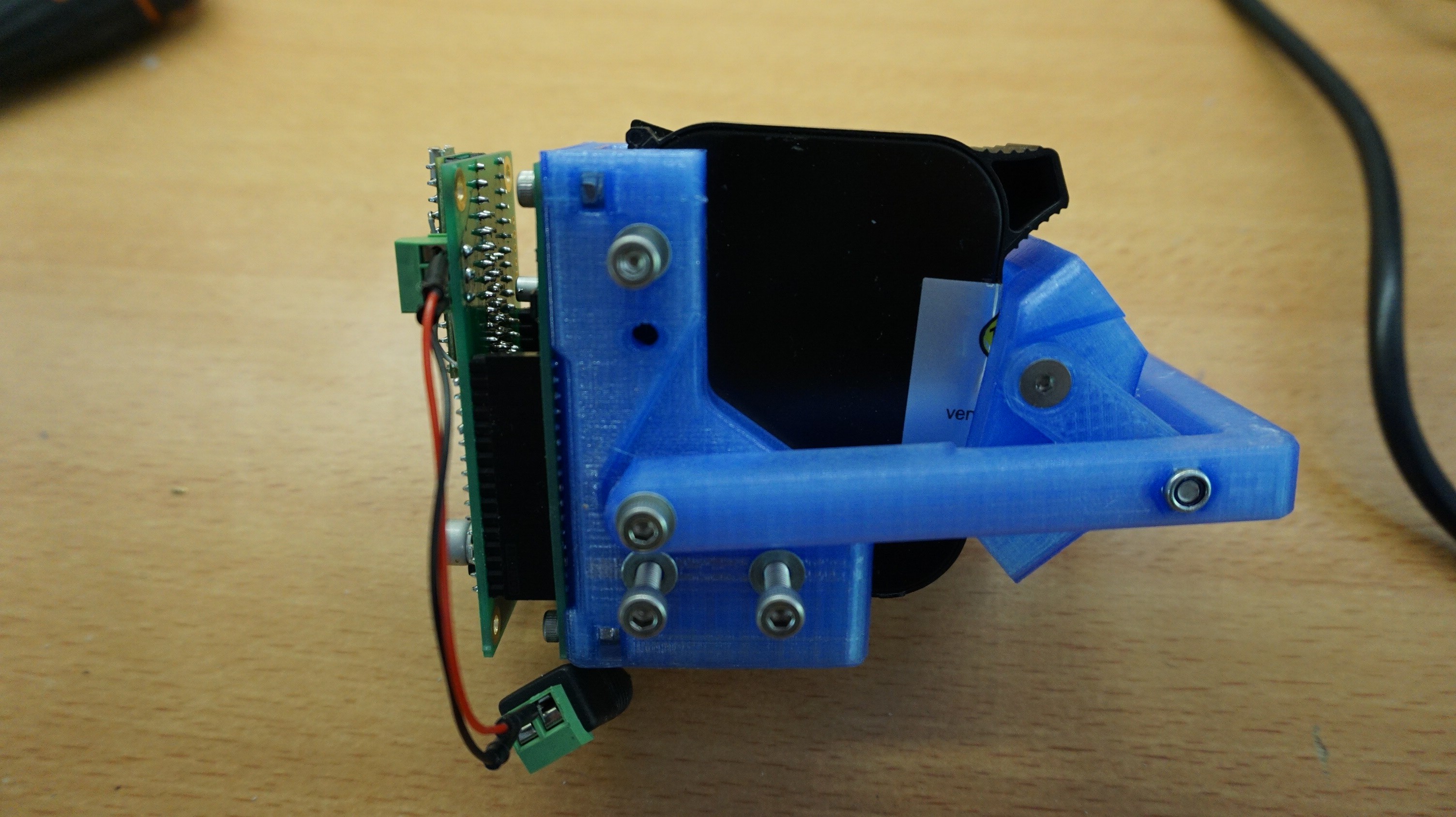
Solder the male headers 2x 1x16, 2.54mm pitch (J4, J5), 1x4 female header, pitch 2.54mm (J3). 1x3 3,5mm screw terminal (J1).![]() Put boards together and enjoy.
Put boards together and enjoy.![]()
![]()
-
3Assembling the frame
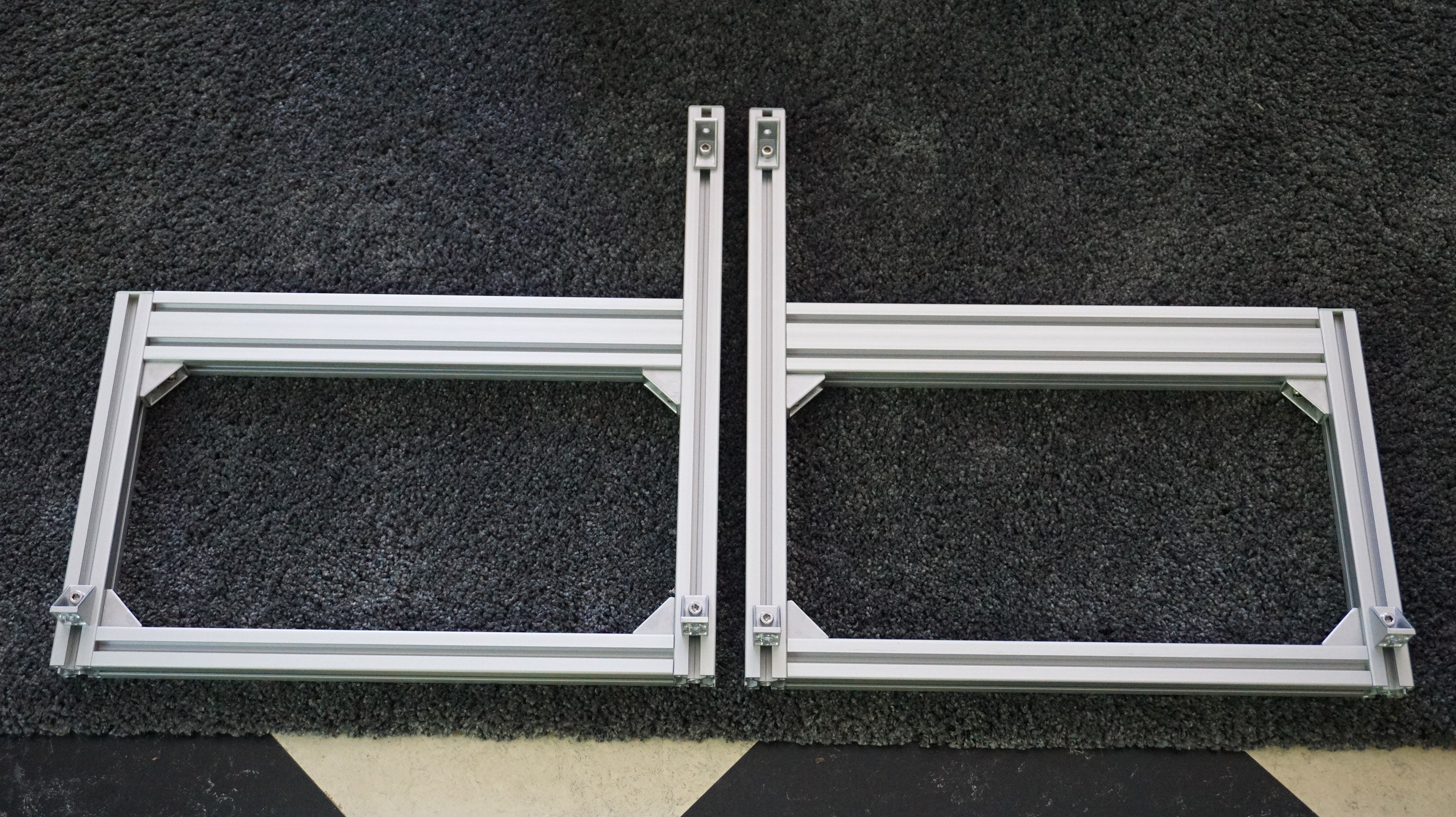
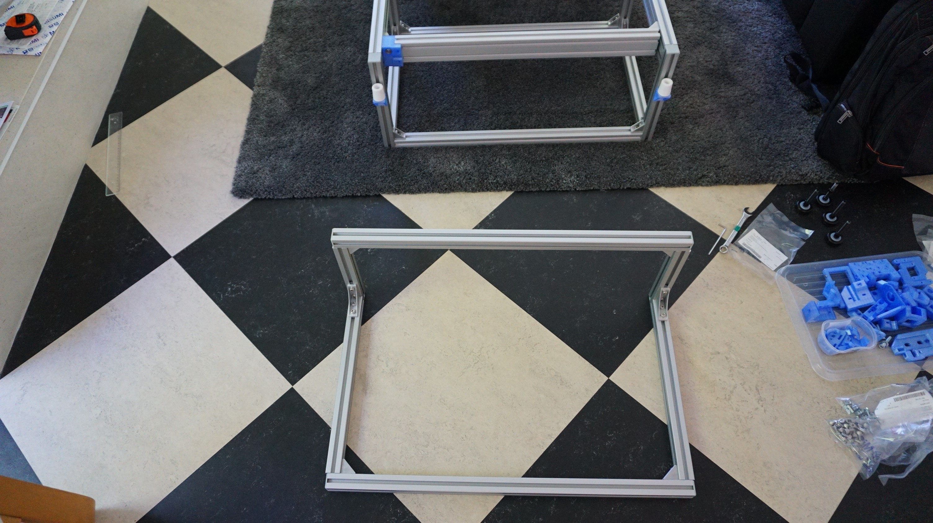
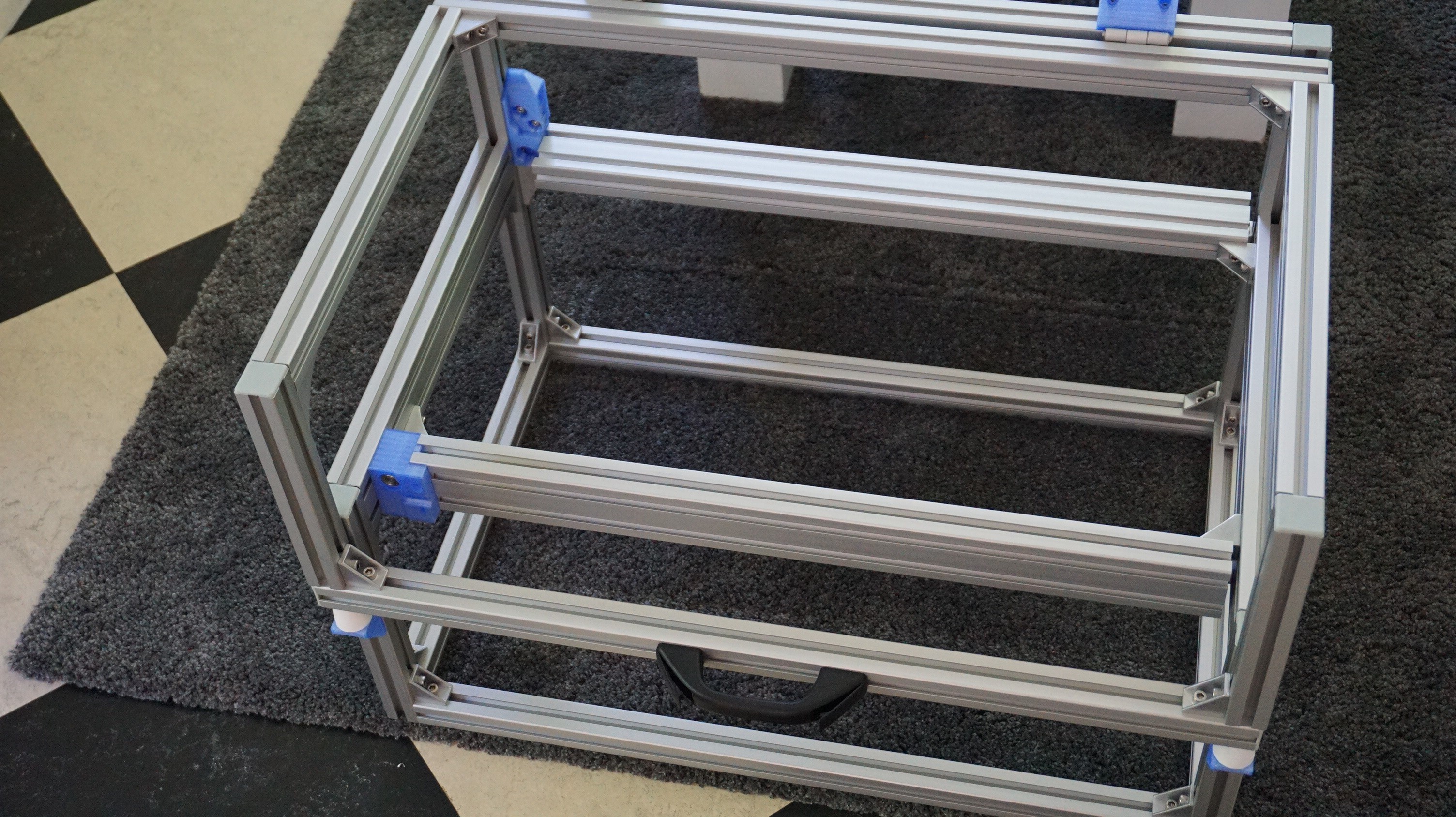
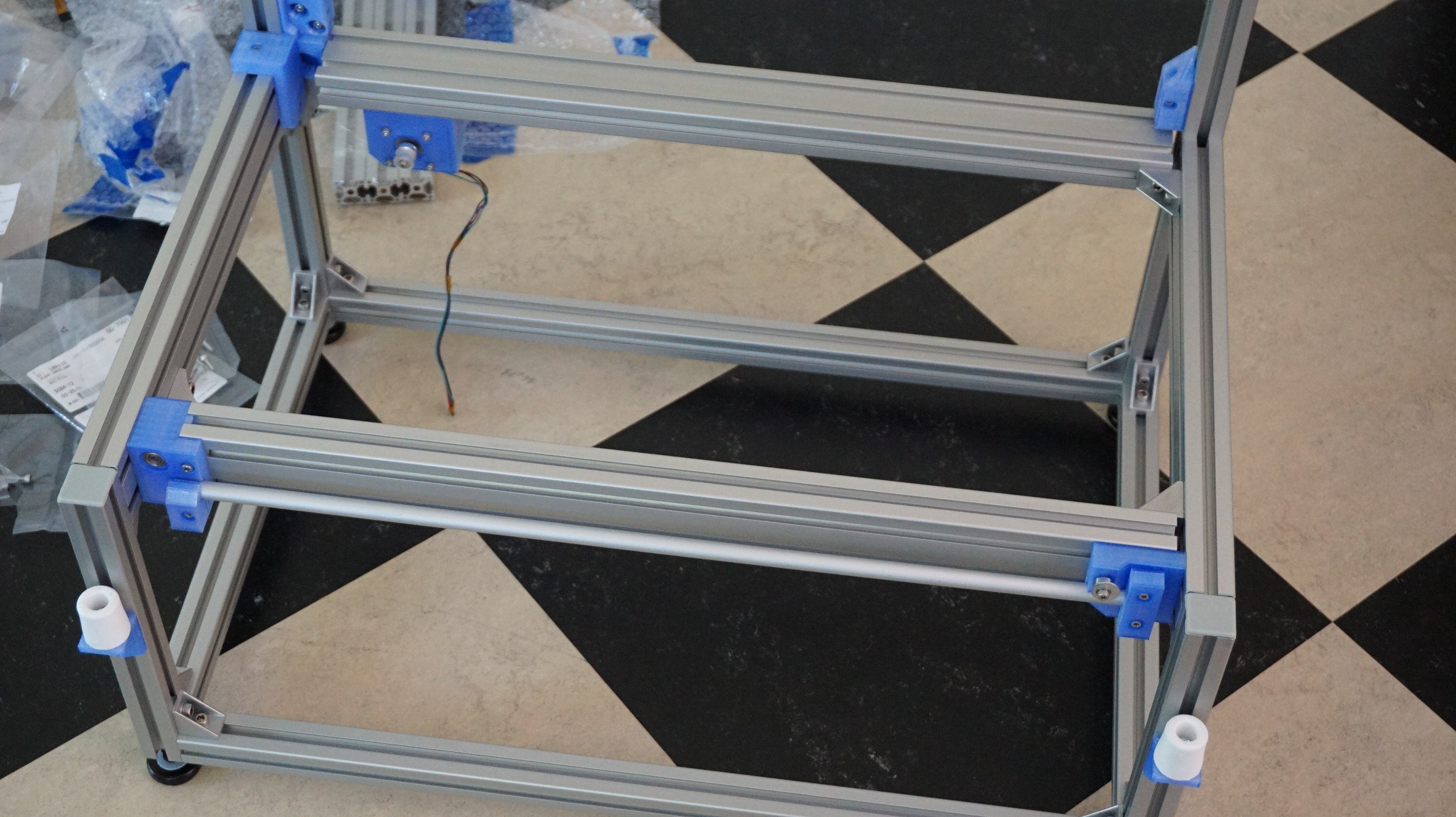
The first component that needs to be built is the base frame. In the drawings this is Y10. The drawings for these parts are: OA-Y10-A01-00 (frame) and OA-Y10-A02-00 (Lid). It is easiest to start with the 2 sides, then add the middle profiles to it. The bottoms of the side frames need to be tapped M8 to hold the feet. The 2 30x60 profiles do not reach all the way. They are 30mm short to allow passage of the X driveshaft and belt.
![]()
![]()
![]()
![]()
![]()
![]()
-
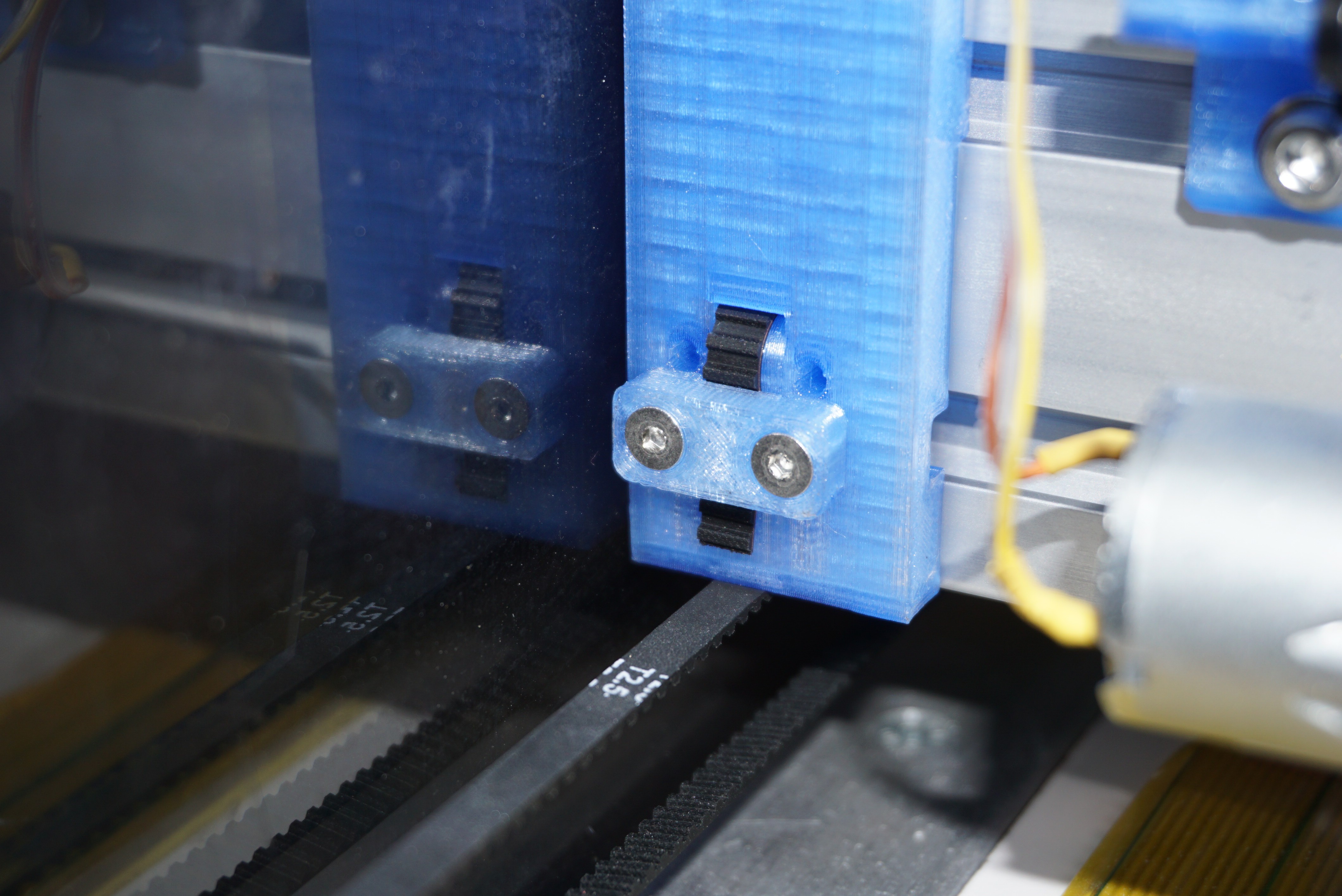
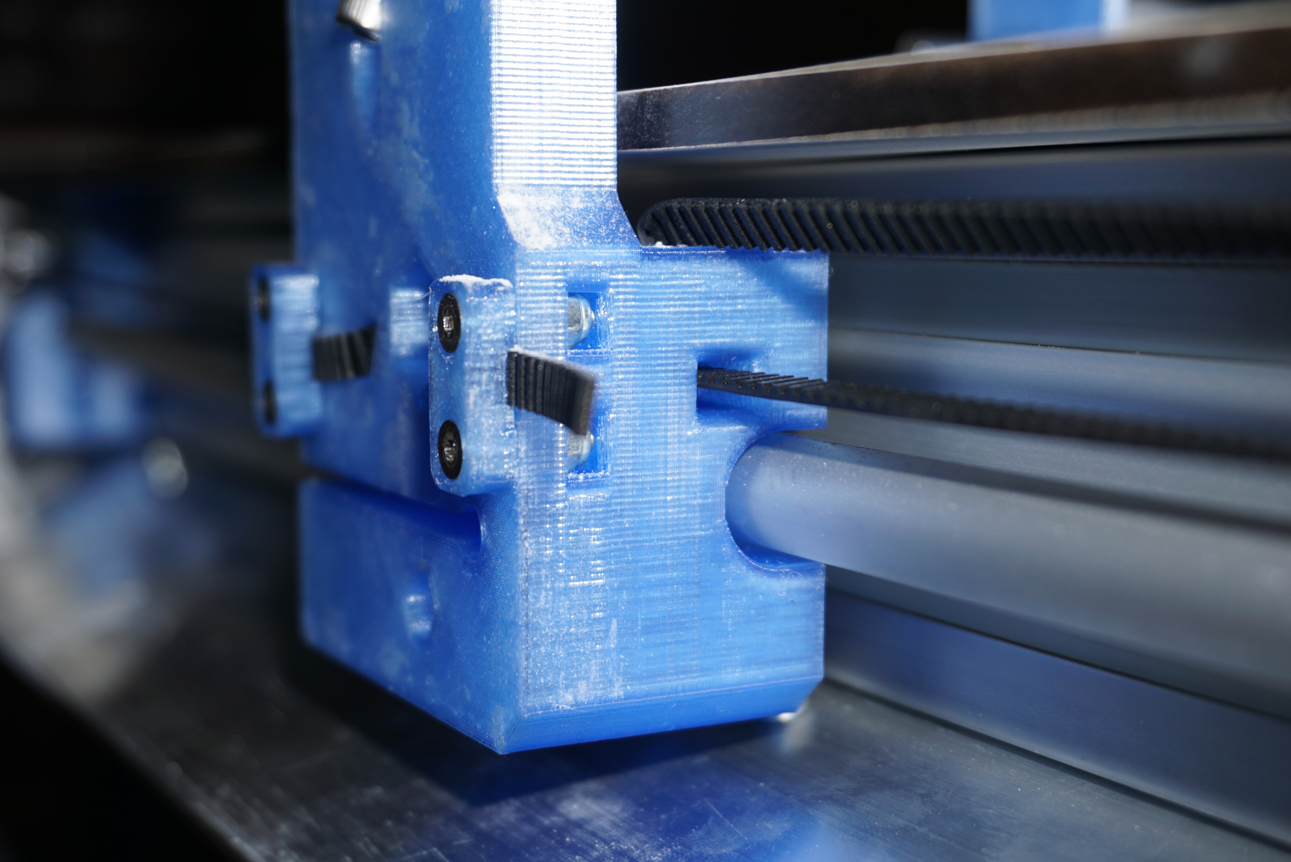
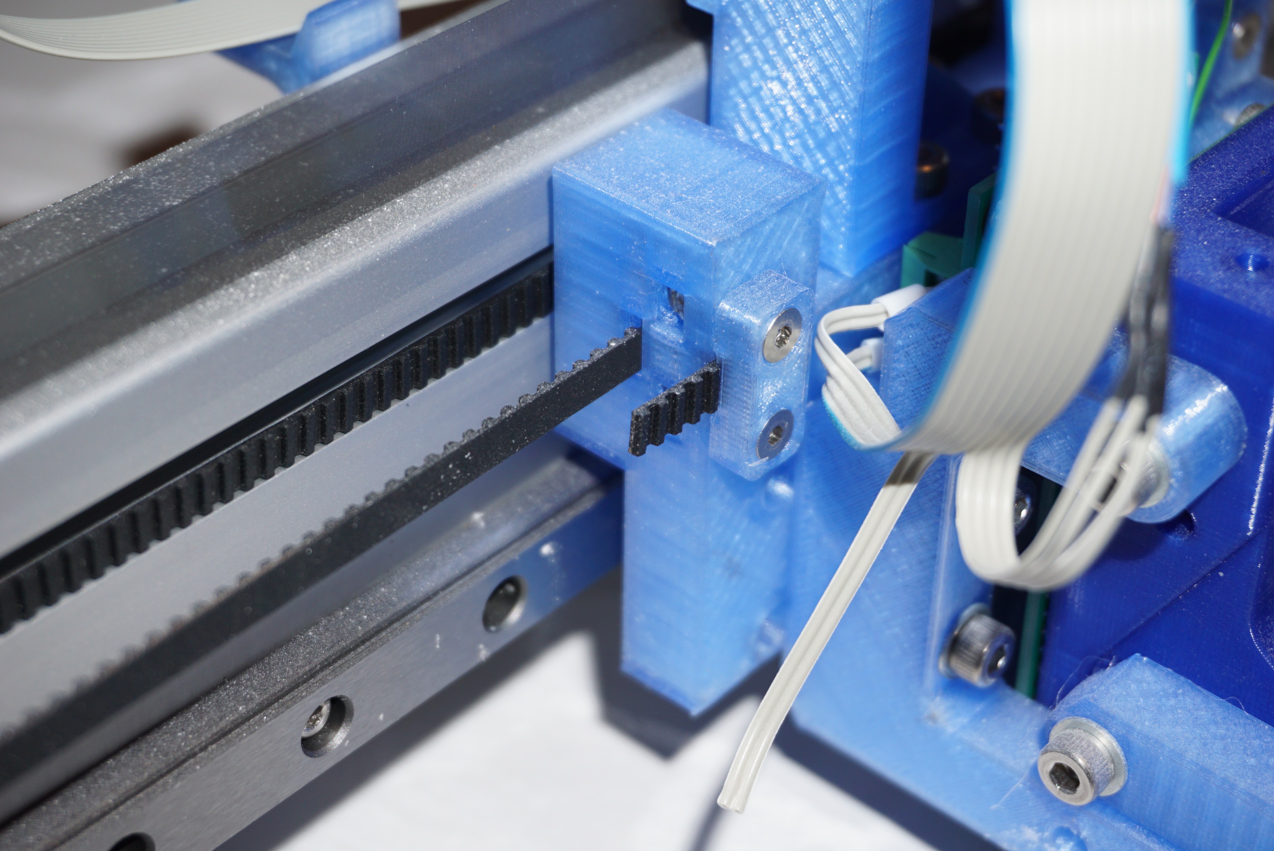
4Assemble the gantry
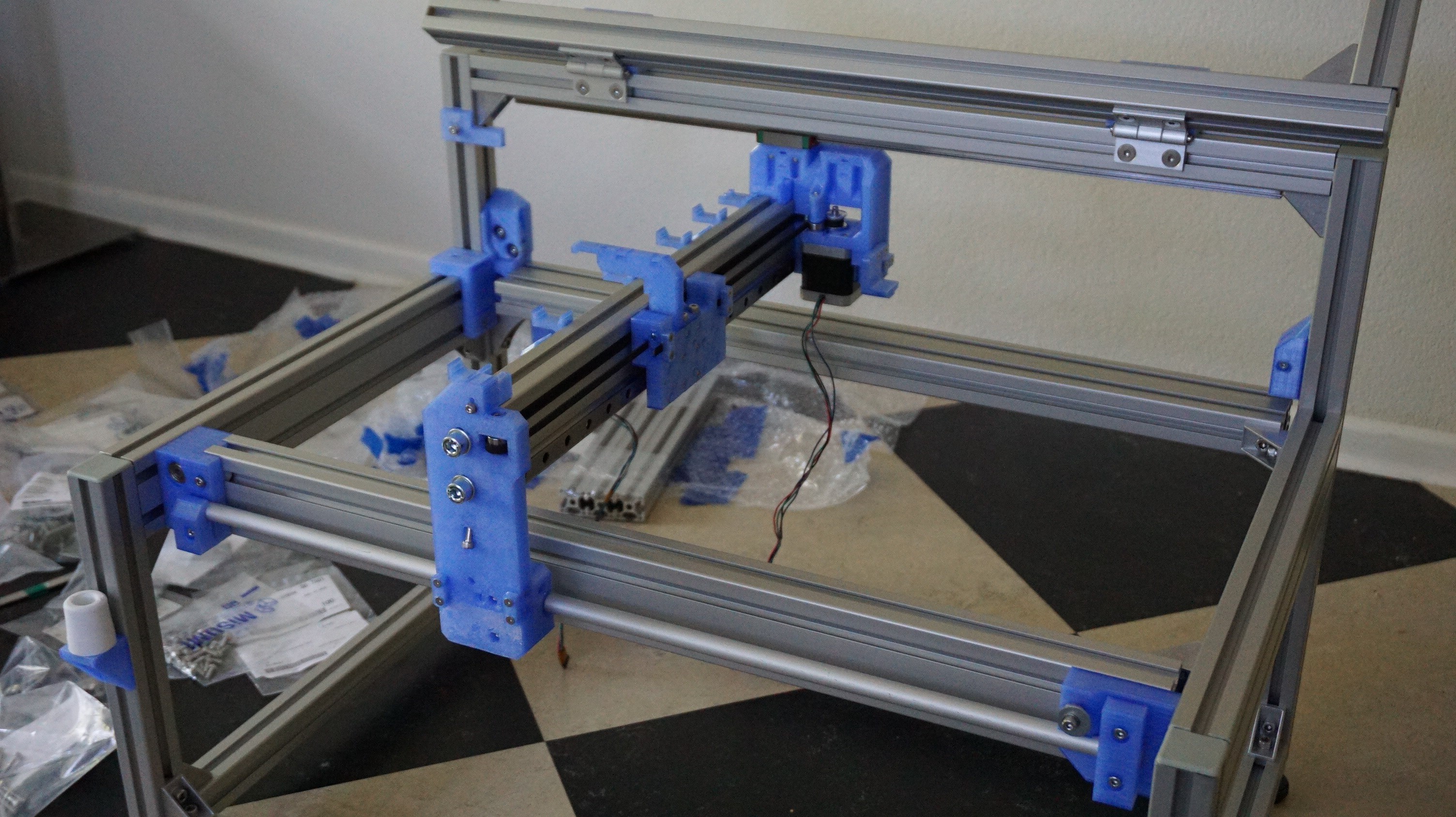
The gantry holds the printhead and the spreader, and moves in the X-direction. In the drawings this is Y20. The drawings for this part is: OA-Y20-A01-02. An important step that may not yet be on the drawings. The 30x60 profile needs to be tapped M8 on both sides to mount the gantry blocks. The timing belts for the block that holds the motor go through holes in the bottom of the block. The timing belts for the 'floating' block enter from the top and make an exotic twist. This is by design.
![]()
![]()
![]()
![]()
![]()
![]()
-
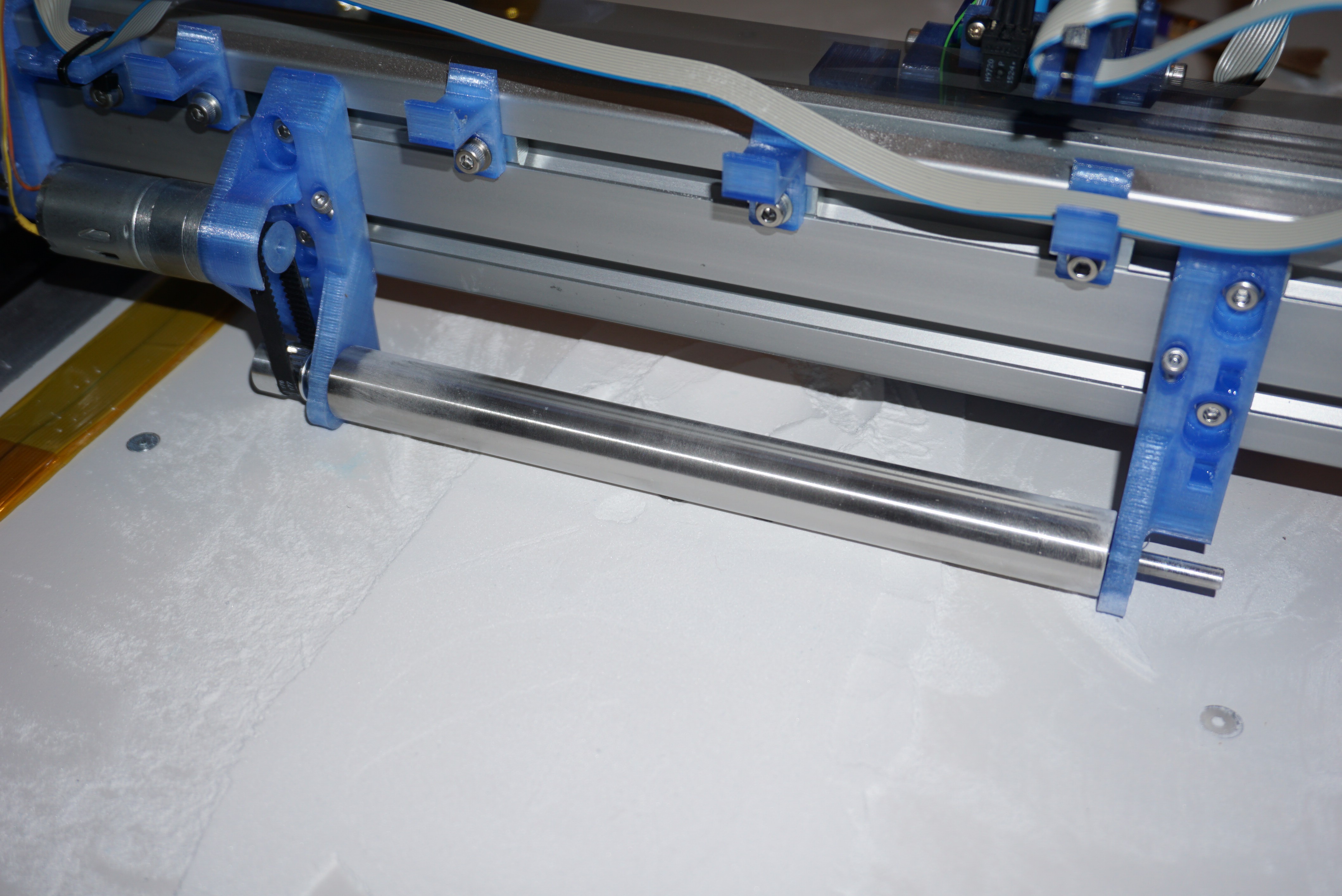
5Assembling the carriage
The carriage is the part that holds the printhead. In the drawings this is Y30. The drawings for this part is: OA-Y30-A01-01. The printhead can be assembled apart from the carriage. It is also usable on it's own (hint, hint).
![]()
![]()
![]()
![]()
-
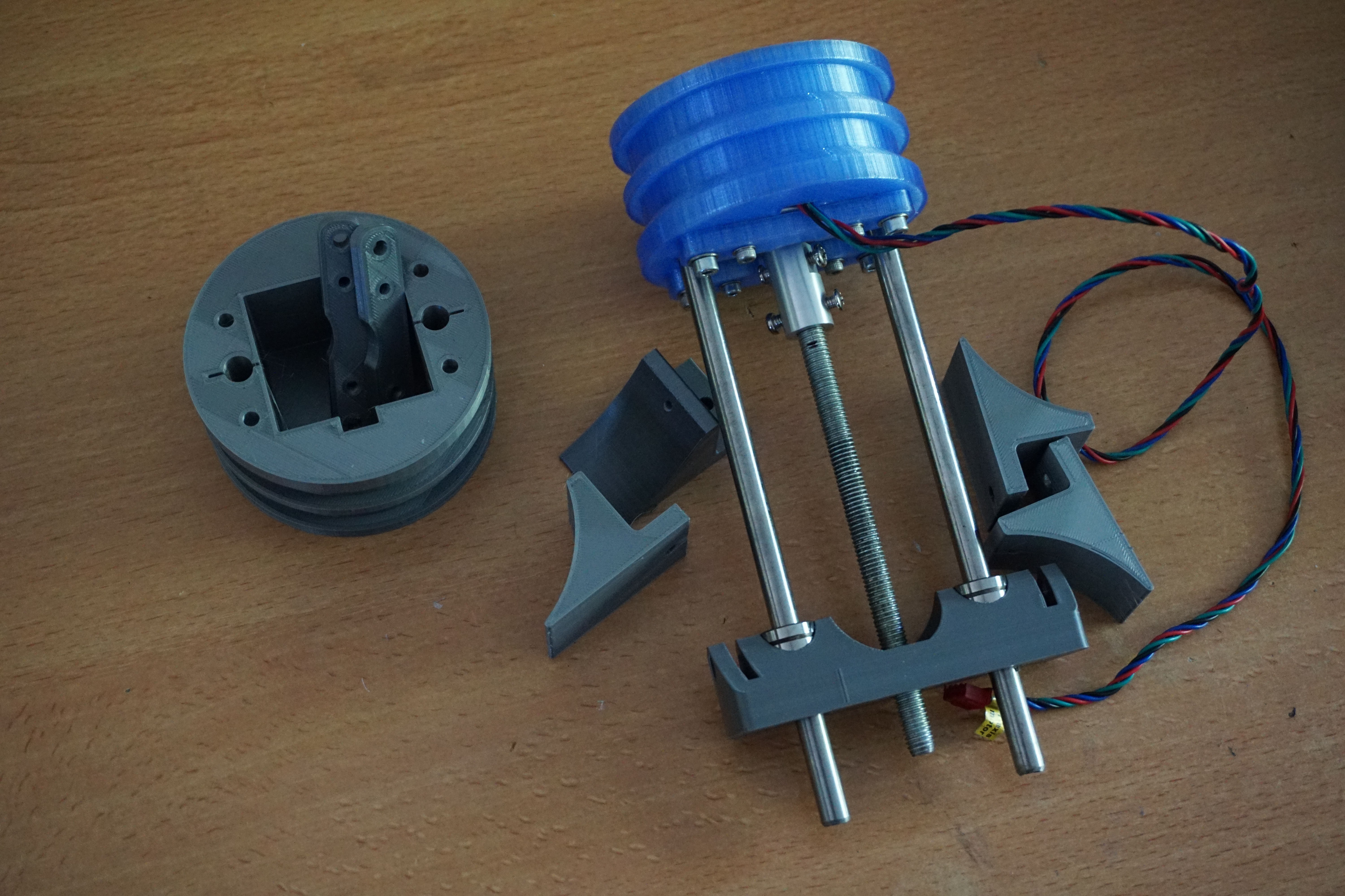
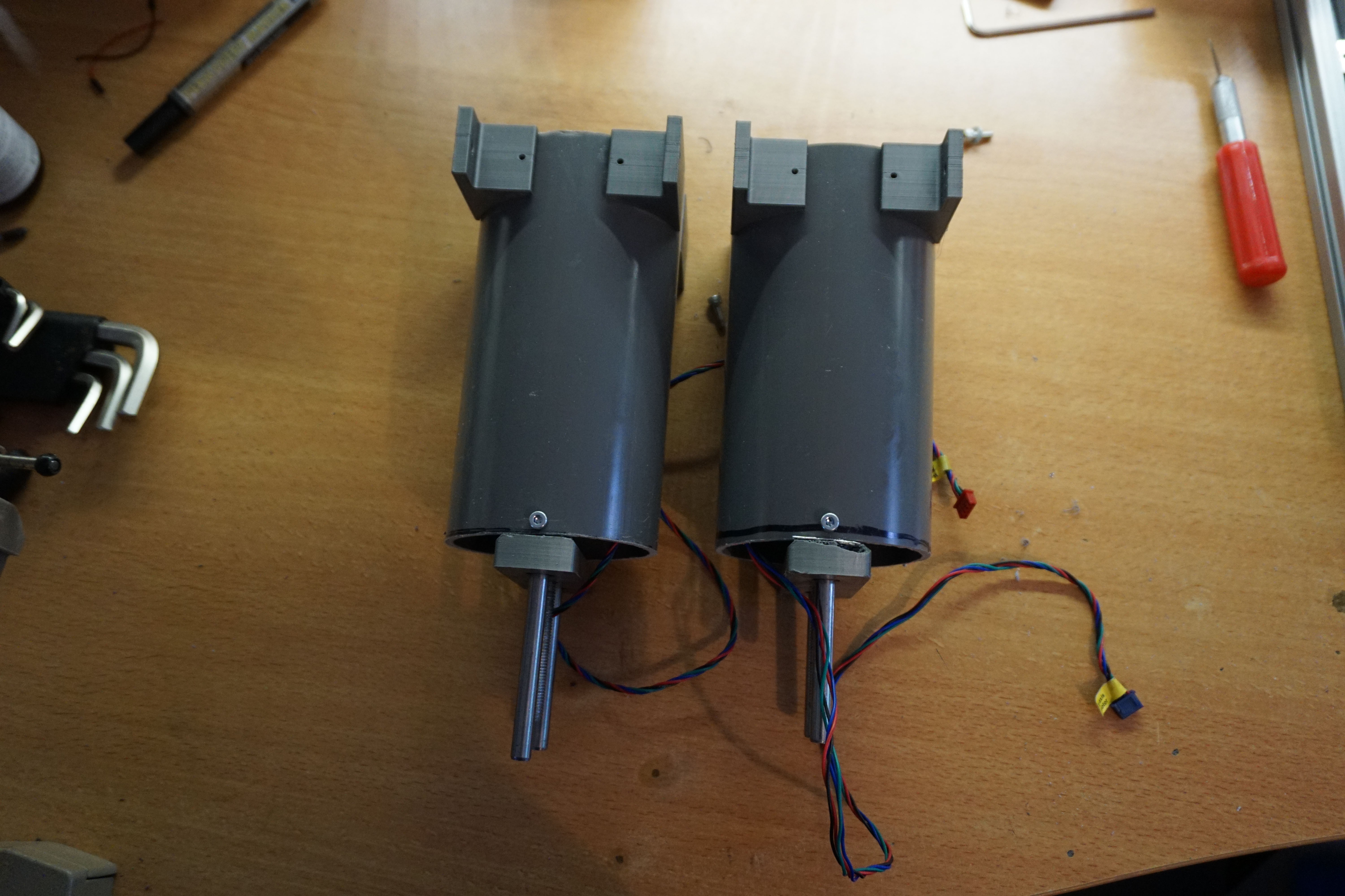
6Assembling the build platform
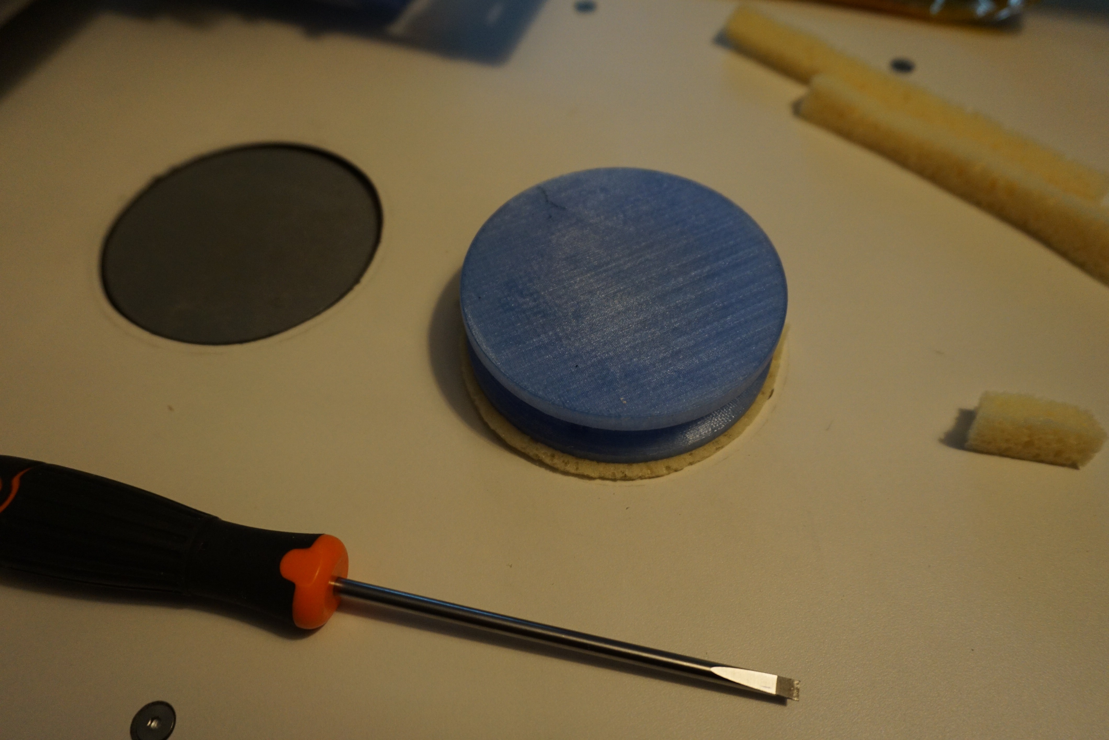
The build platform holds the pistons and is used to build the part in. In the drawings this is Y40 (build surface) and Y50 (pistons). The drawings for this part is: OA-Y40-A01-01 and OA-Y50-A02-00. For the main surface I use HPL, a laminate with a smooth melanine surface. It does clean easily, but does have a tendency to chip. Take your time when cutting and drilling it. The notch in the top left corner is for the cables to pass through.
The pistons are assembled separately and mounted under the bed using 3 30x30 profiles (not shown in photo's). The pistons use sponge as a seal to keep the powder in the piston.
![]()
![]()
![]()
![]()
![]()
-
7Assembling the bin
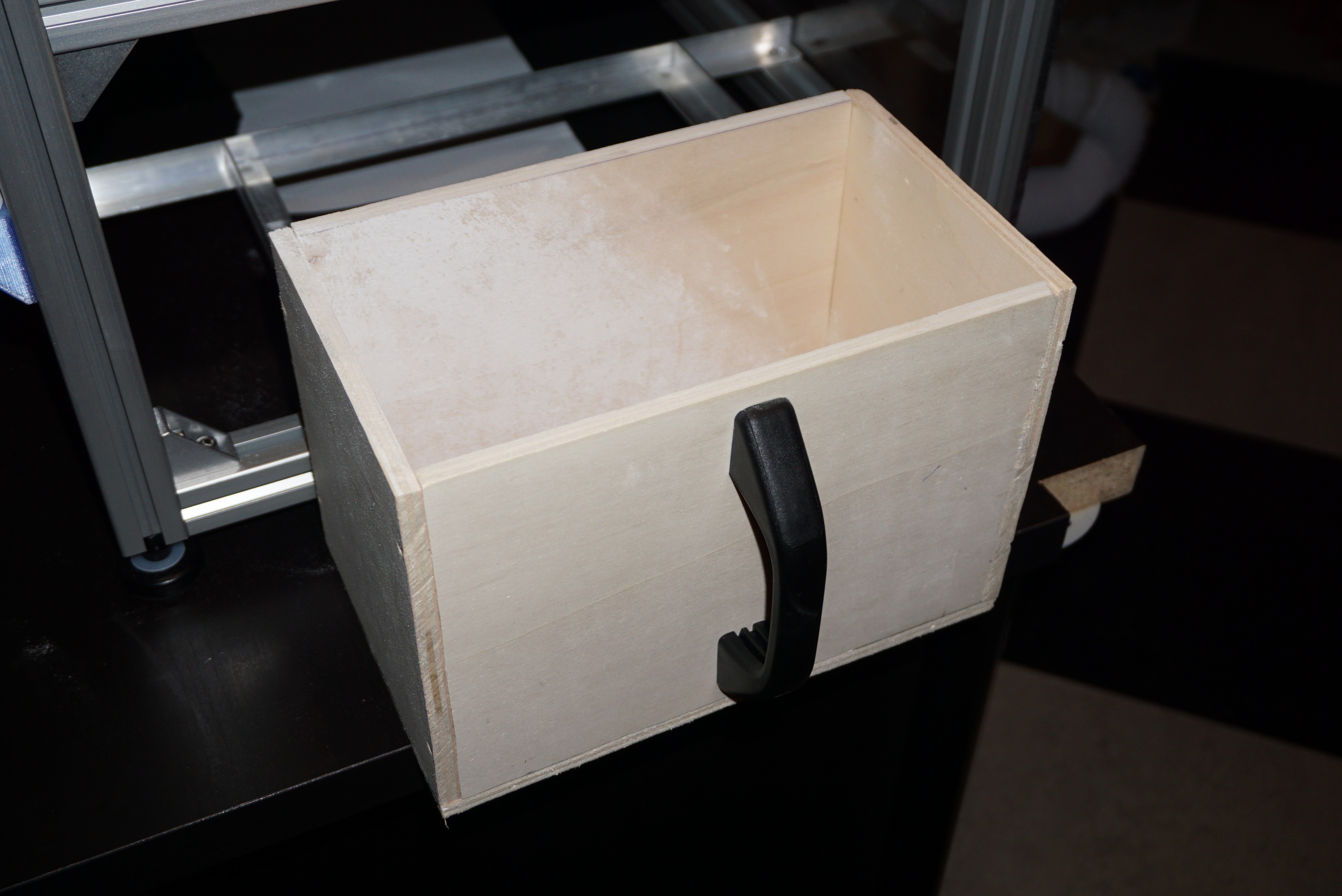
The bin captures the excess powder. In the drawings this is Y15. The drawings for this part is: OA-Y10-A01-00. Not much to it really. A rectangular, wooden bin.
![]()
-
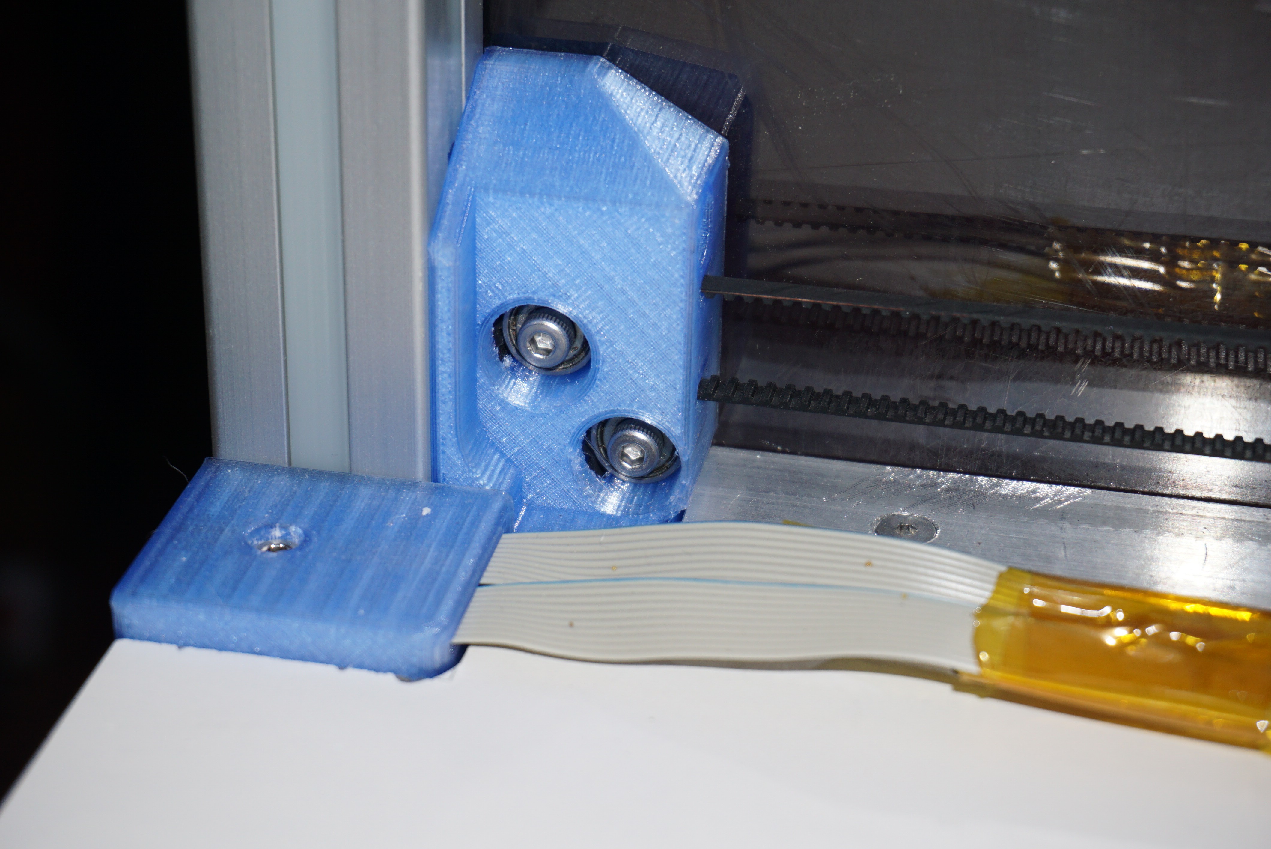
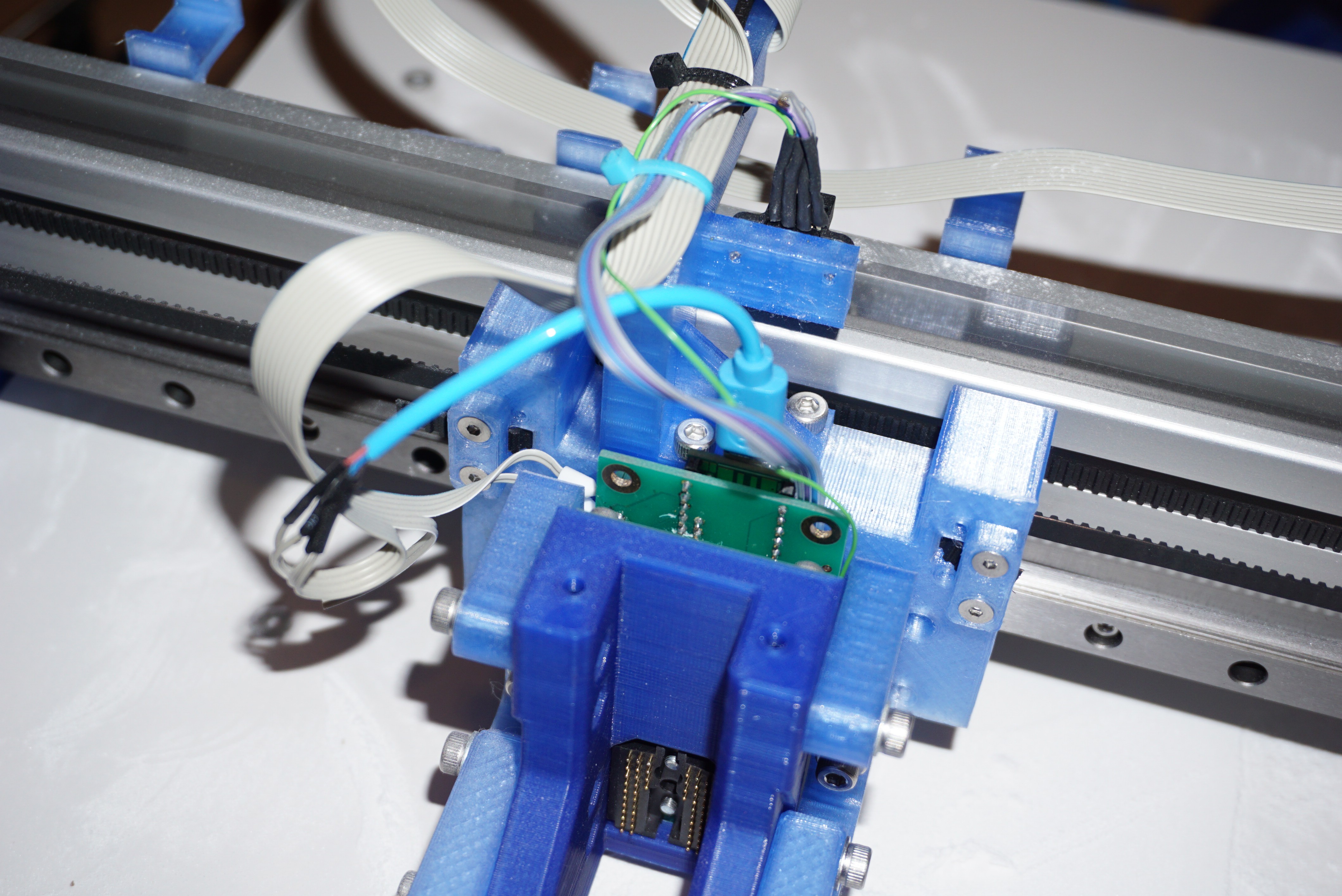
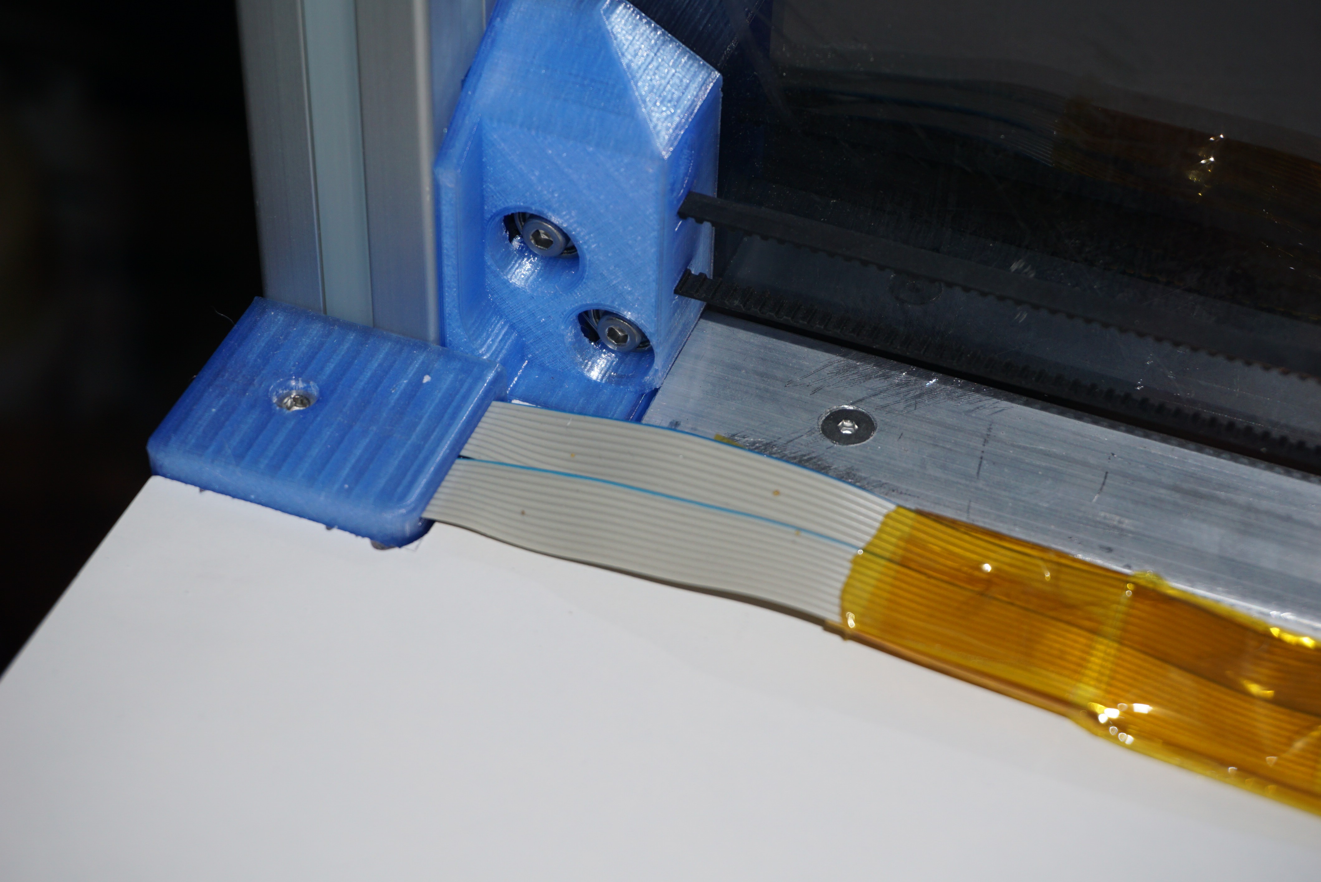
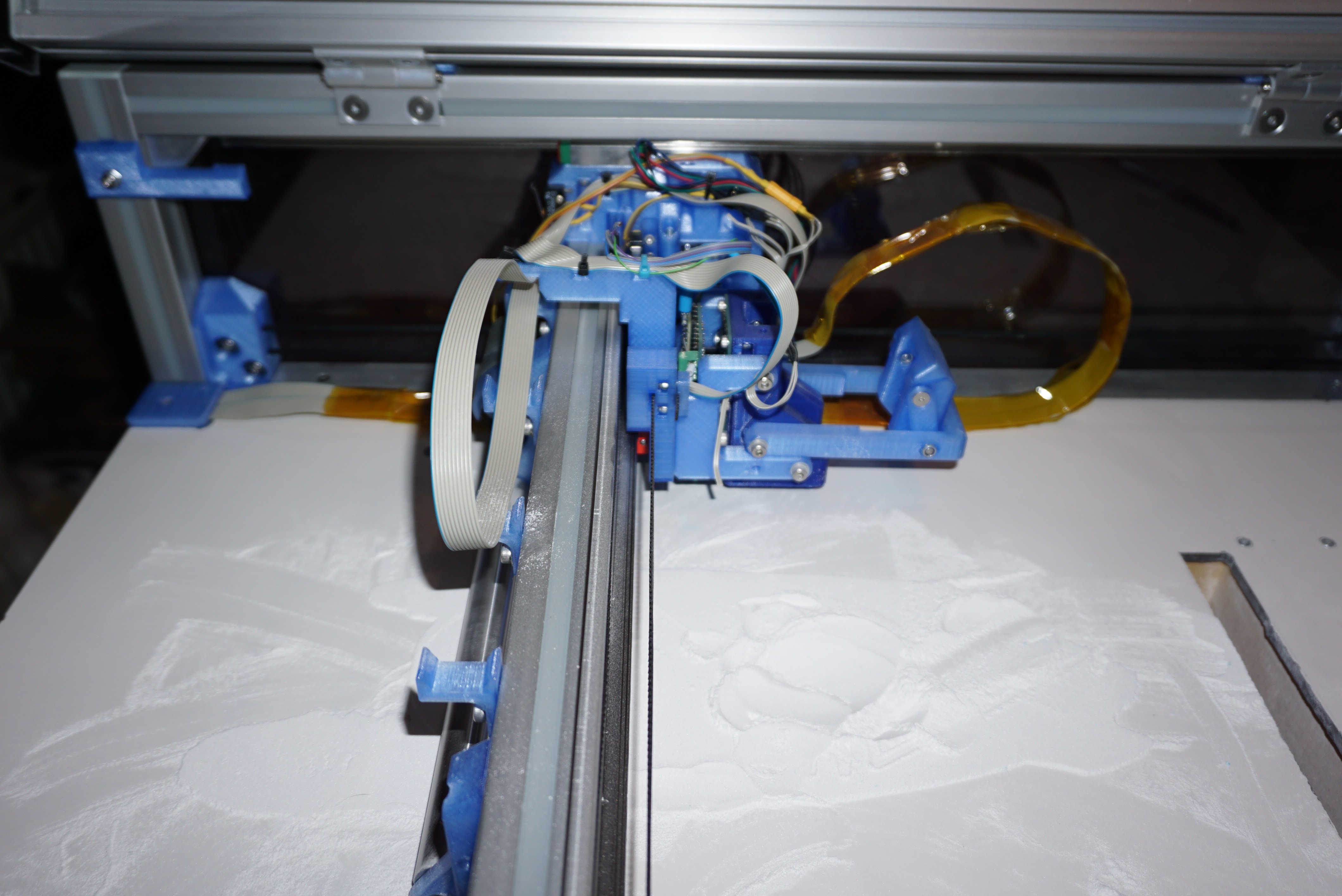
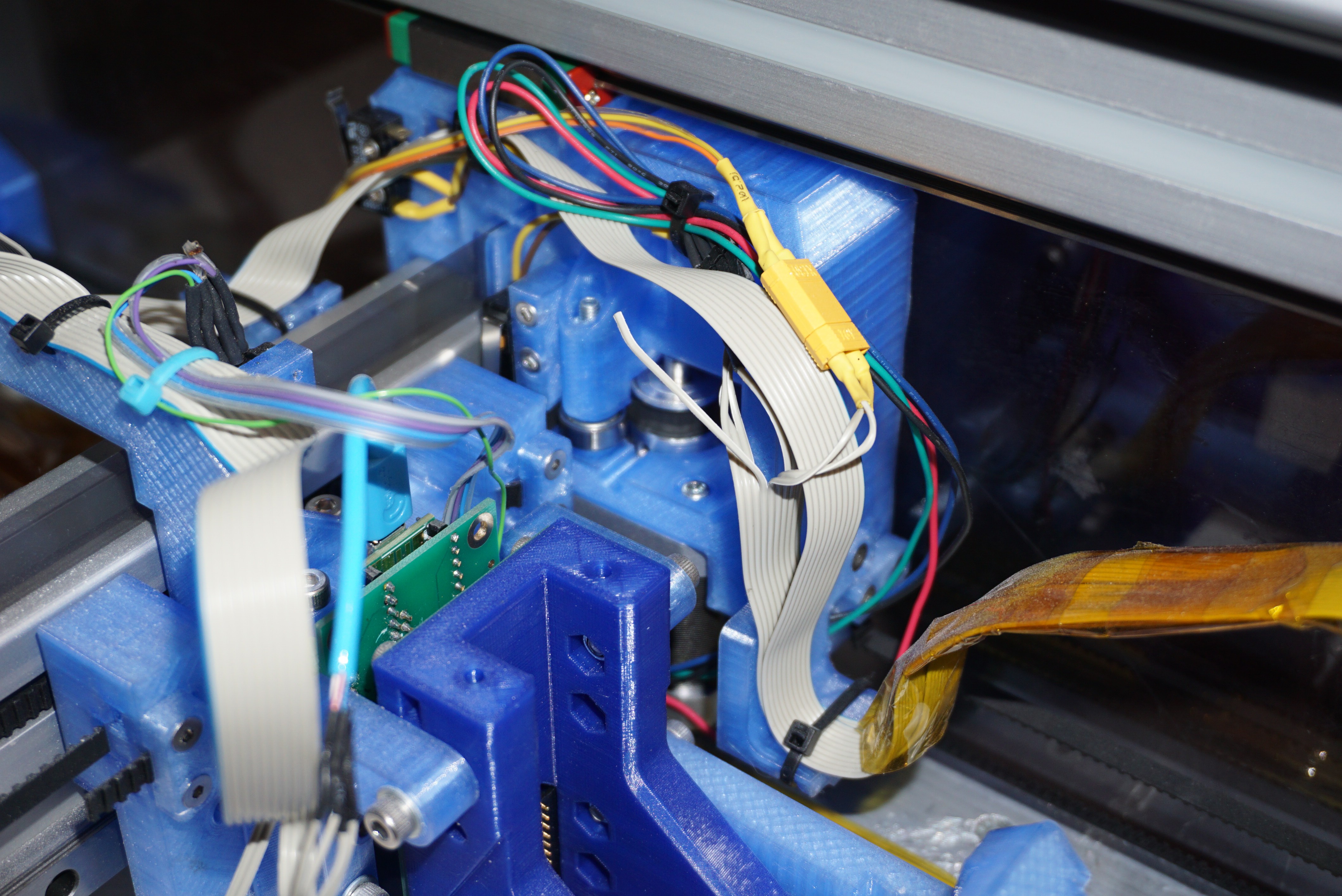
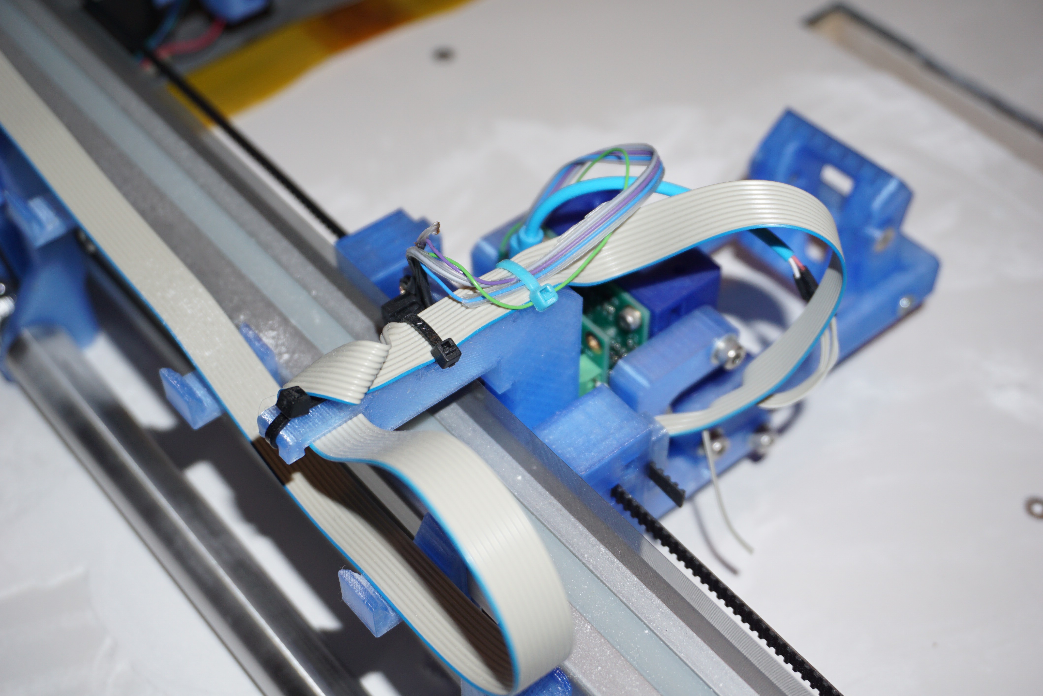
8Wiring Oasis
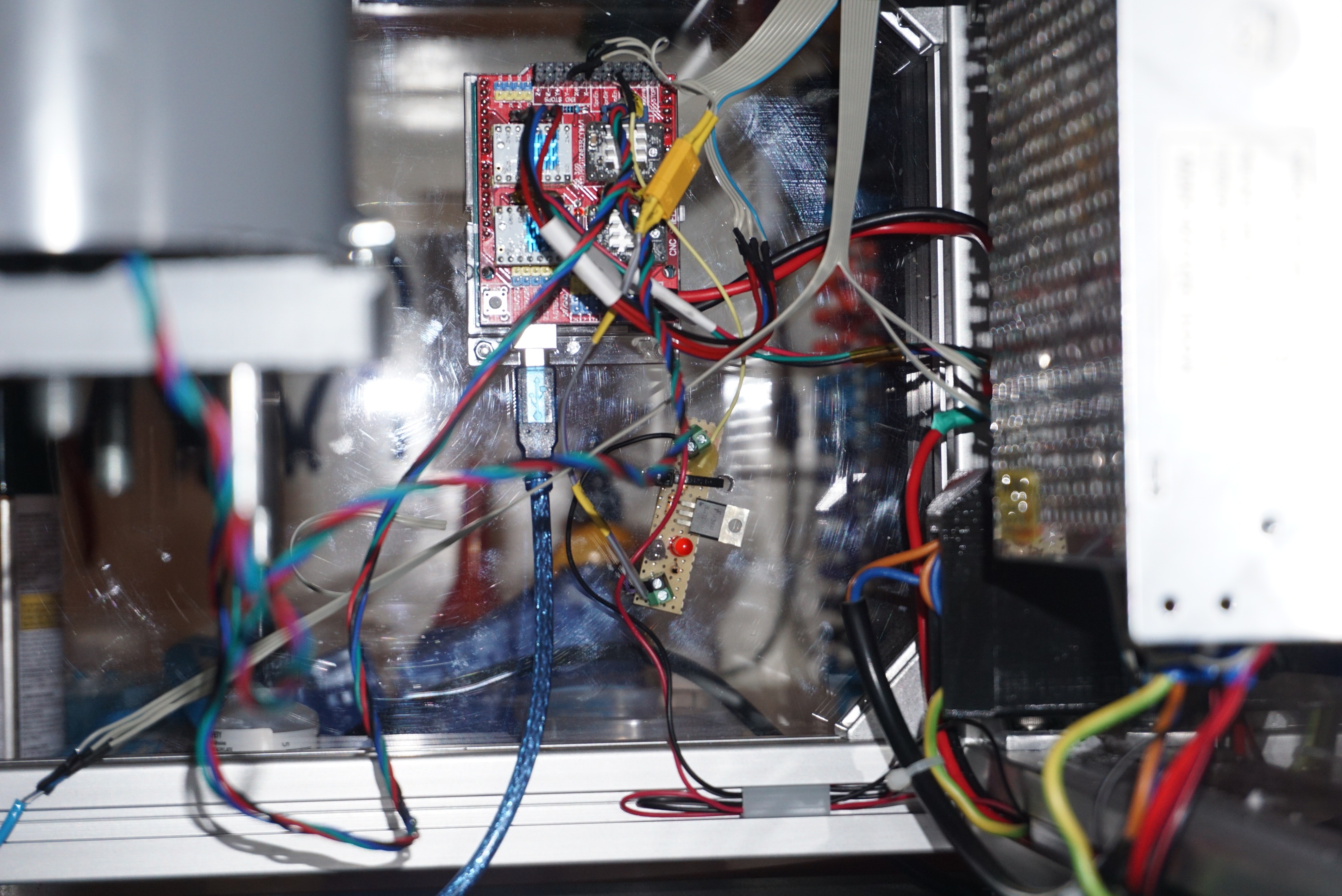
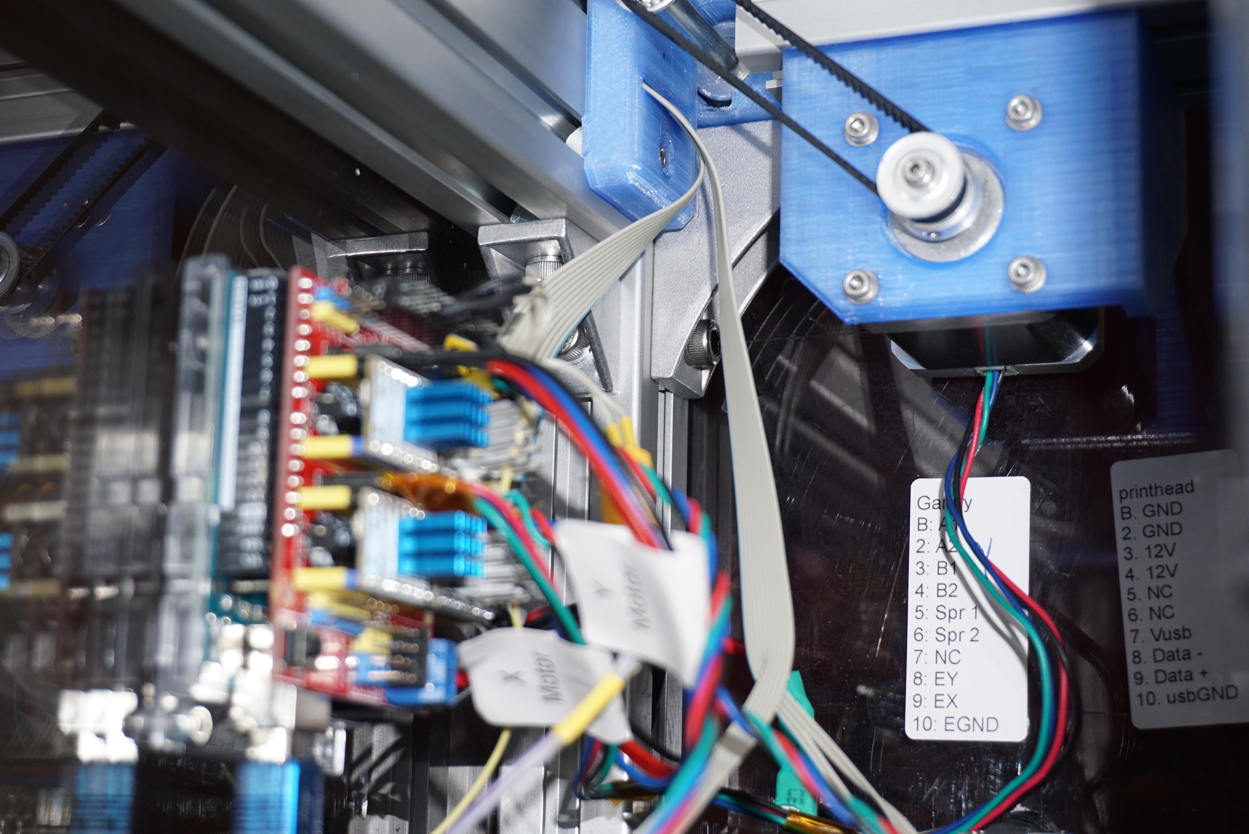
Once Oasis is assembled, the printer can be wired up. The wiring under the printer consists of 12V power supply, fuses, GRBL (with x motor and 2 pistons) and the spreader circuit. Near the back left of the printer is a special part that gives a dust free path to the top of the build area. From here, the wiring is managed in 2 10 wire flatcable paths. The 2 flatcables go to the gantry. The first of the flatcables now splits up into 4 motor wires, 3 encoder wires (2 signal, 1 ground) and 2 spreader motor wires. The other cable goes over a cable guide to the printhead, and has 2 12V wires, 2 ground wires and 4 USB signal wires.
![]()
![]()
![]()
![]()
![]()
![]()
-
9Flashing the firmware
For this step you will need the Arduino IDE, and teensyduino installed.
HP45
Connect the Teensy 3.2 on the HP45 board with USB to the PC. For the HP45 firmware, Open "HP45_Standalone_V3.00.00" (or higher) from the make package->Firmware->HP45 in the Arduino IDE. Select Teensy 3.2 from the boards, select "96MHz (Overclock)" for speed, and select the port the Teensy is on. Compile and flash the firmware. If no errors were returned, the firmware should now be running. You can try this by sending "GTP" to the printhead through the serial monitor (With NL or carriage return on). It should echo "GTP n" where n is a value.
HP45 standalone only depends on the external "Encoder" library, which should be included with Teensyduino.
GRBL
For the GRBL controller, first in the find the folder "grbl" in Make package->Firmware->GRBL->GRBL Uno 4 axis->grbl-master. Find where Arduino stores libraries. On windows, this is usually "C:\Users\'yourname'\Documents\Arduino\libraries". Copy the lasy folder called 'grbl' there. Now, in arduino, under file->examples you should find a grbl option. Go here, and pick 'grblUpload'. Select arduino Uno, the right port and upload this sketch to the Arduino Uno controlling the CNC shield.
In most cases this should be it, but GRBL is a bit special. More information on configuring GRBL can be found here. It will say there is a newer version of GRBL. Ignore that. Oasis uses 0.9 because it has a branch of GRBL that can handle 4 axes.
Connect the Arduino Uno with the CNC shield with USB, and through the Arduino serial monitor, with 115200 baud, connect to the Arduino. You should be greeted with a GRBL version. Now type '$$' to get the current configuration of GRBL. This is not correct for Oasis. The desired values are in a file 'Default settings.txt' where the GRBL library was found. A copy of that list is also below. You can set a setting by typing '$100=80' for instance. This will set the X steps per millimeter to 80. Do this for all values that do not match the list below.
$0=10 (step pulse, usec)
$1=255 (step idle delay, msec)
$2=0 (step port invert mask:00000000)
$3=2 (dir port invert mask:00000010)
$4=0 (step enable invert, bool)
$5=0 (limit pins invert, bool)
$6=0 (probe pin invert, bool)
$10=2 (status report mask:00000010)
$11=0.010 (junction deviation, mm)
$12=0.002 (arc tolerance, mm)
$13=0 (report inches, bool)
$20=0 (soft limits, bool)
$21=0 (hard limits, bool)
$22=1 (homing cycle, bool)
$23=1 (homing dir invert mask:00000001)
$24=300.000 (homing feed, mm/min)
$25=3000.000 (homing seek, mm/min)
$26=250 (homing debounce, msec)
$27=5.000 (homing pull-off, mm)
$100=80.000 (x, step/mm)
$101=80.000 (y, step/mm)
$102=2560.000 (z, step/mm)
$103=2560.000 (A, step/mm)
$110=18000.000 (x max rate, mm/min)
$111=18000.000 (y max rate, mm/min)
$112=200.000 (z max rate, mm/min)
$113=200.000 (A max rate, mm/min)
$120=500.000 (x accel, mm/sec^2)
$121=500.000 (y accel, mm/sec^2)
$122=100.000 (z accel, mm/sec^2)
$123=100.000 (A accel, mm/sec^2)
$130=500.000 (x max travel, mm)
$131=350.000 (y max travel, mm)
$132=100.000 (z max travel, mm)
$133=100.000 (A max travel, mm)
GRBL is now ready for use.
-
10Converting an STL to SVG for Oasis using Slic3r
For technical reasons Oasis uses Slic3r SVG's. Before a file can be 3D printed, it needs to be converted using Slic3r. For this instruction I will use Slic3r 1.2.9 on windows 8.1. Since this can be a bin finicky, this guide.
Configuring slicer
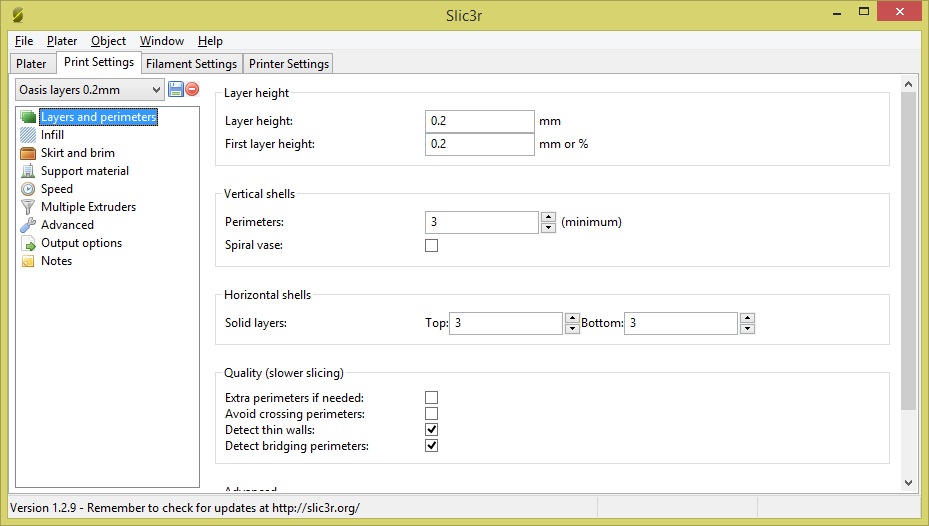
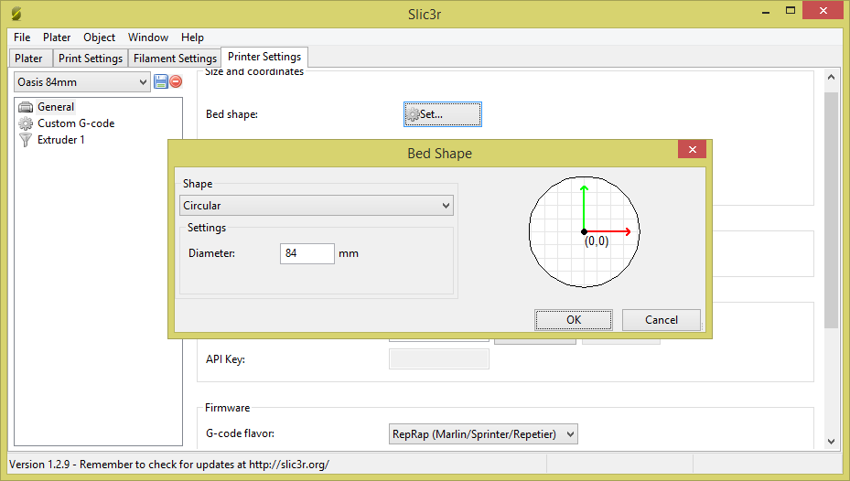
After having downloaded and installed Slic3r, open it. There are 2 settings of interest before you can use Slic3r. Layer height and print area. In layer height you want both your first layer and layer height to the value you want to print at. In my case this is 0.2mm right now. An optional but handy setting is bed shape and size. Set this to you printer bed shape, so you won't try to print too big. I use 84mm round. In both settings, set what you need, then press the save button on the left and name it whatever.
![]()
![]()
Orienting an STL
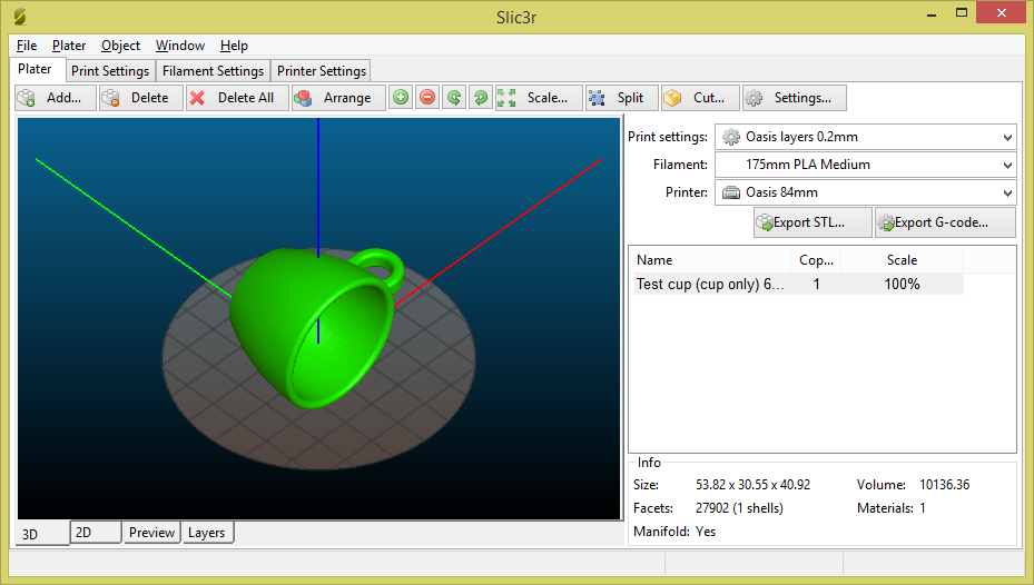
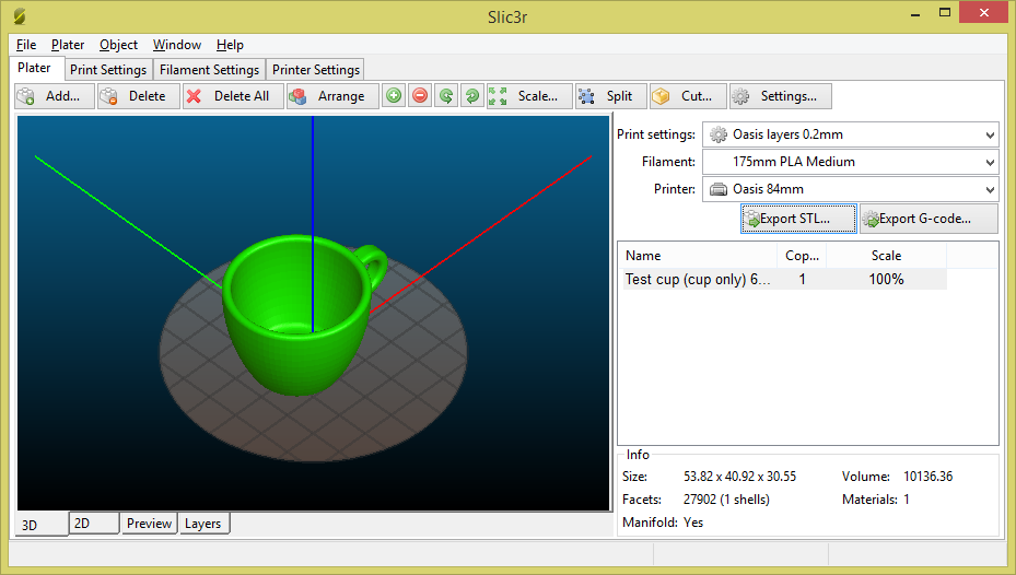
Not all STL's are oriented correctly. If you work in Solidworks they rarely are. Slic3r Slice to SVG does not use the Plater window, but slices straight from the STL file. This means that you will have to orient your part and save it. Load the file you want to print into Slic3r. Use the 'right mouse button>Rotate' to orient the part for printing. Scaling is also possible with 'right mouse button>Scale. Then press 'Export STL' and save your file in a place where you can find it.
![]()
![]()
Converting and STL to SVG
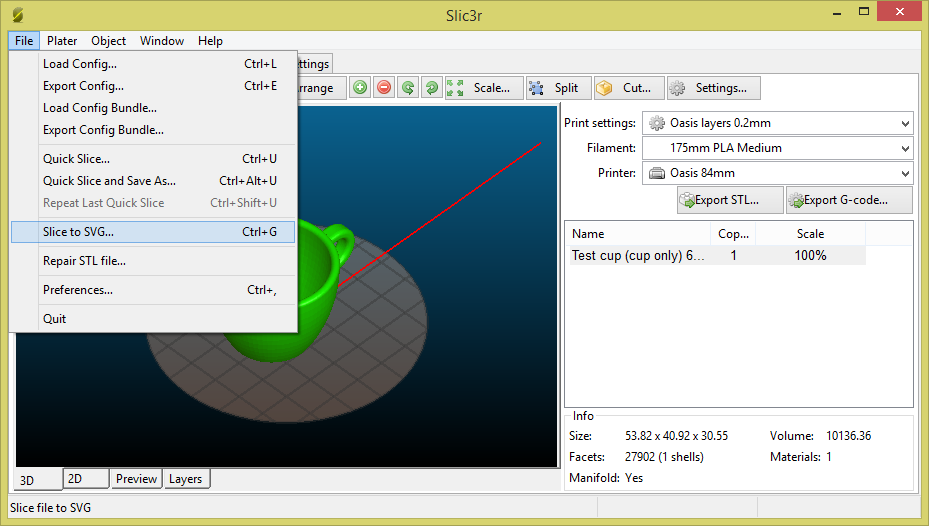
When you are sure your STL file has the right size and orientation, go to 'File>Slice to SVG...' It will first ask you what file to slice, then where to save it (and under what name, be sure it will be called .svg), then give a confirmation when it is sliced. The saved SVG file is now ready for use in Oasis controller.
![]()
![]()
Oasis 3DP
A powder and inkjet 3D printer based on HP45 inkjet technology
 Install the mosfets. There are several types. Q1 and Q2 are the small ones. They are PMV20CNER and have a SOT-23 footprint. They only serve to shift level, so any low threshold voltage N channel mosfet should work. Q3 is the big one. It is a SIRA12DP-T1-GE3 in an SO-8 power pack. It needs low on resistance and a gate voltage lower than 3V. The dot marks the orientation for Q3.
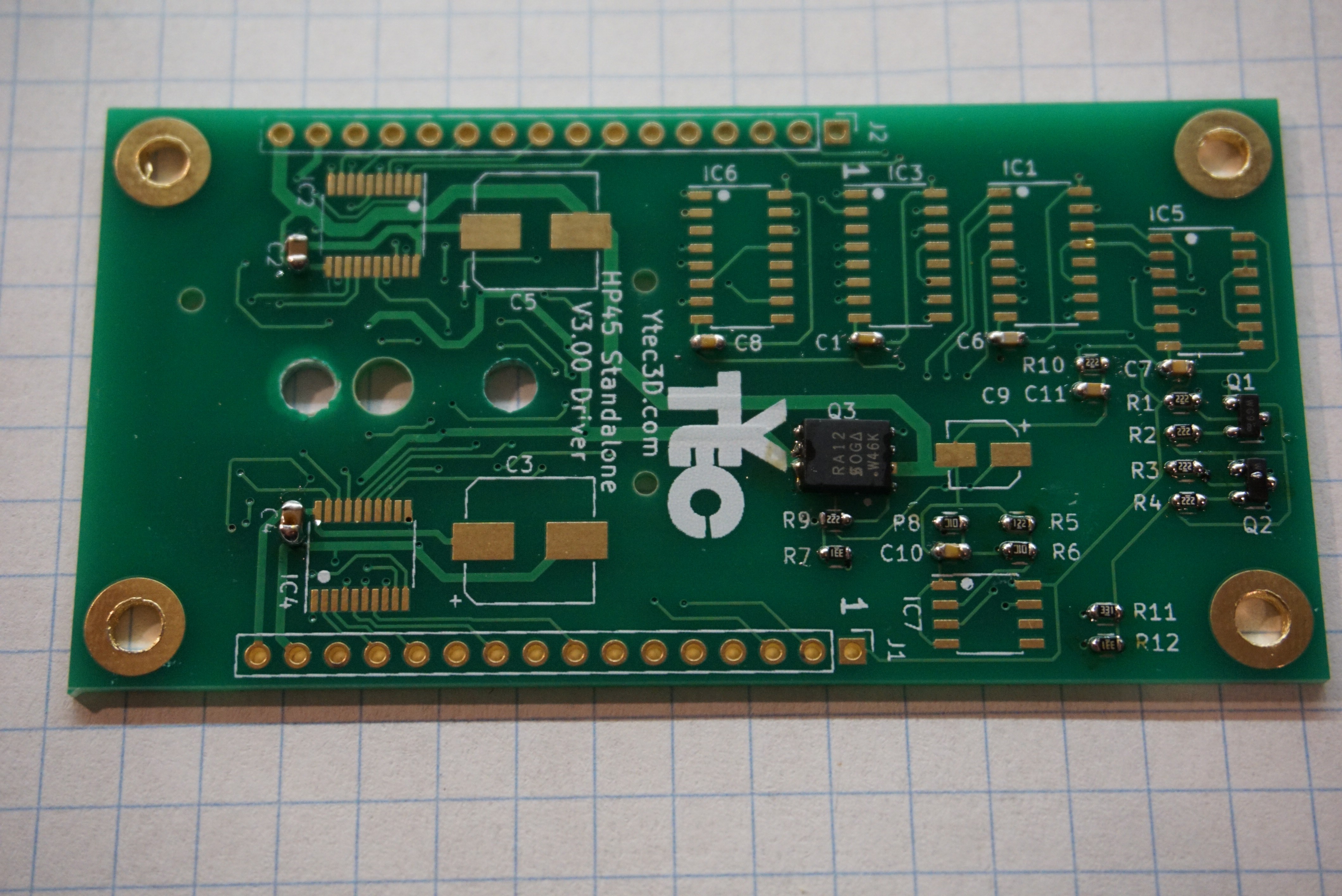
 Install the Electrolytic capacitors. C3, C5 are 100uF, 16V minimum, package 8mm, height lower than 10mm. C9 is 1uF, 16V minimum, package 4mm.
 Mount the HP45 connector using M3x6 or #6 screws (I am experimenting with #6, if they behave I will include them in what I sell. The holes are not actually big enough for #6, so I do have to ream the holes right now.
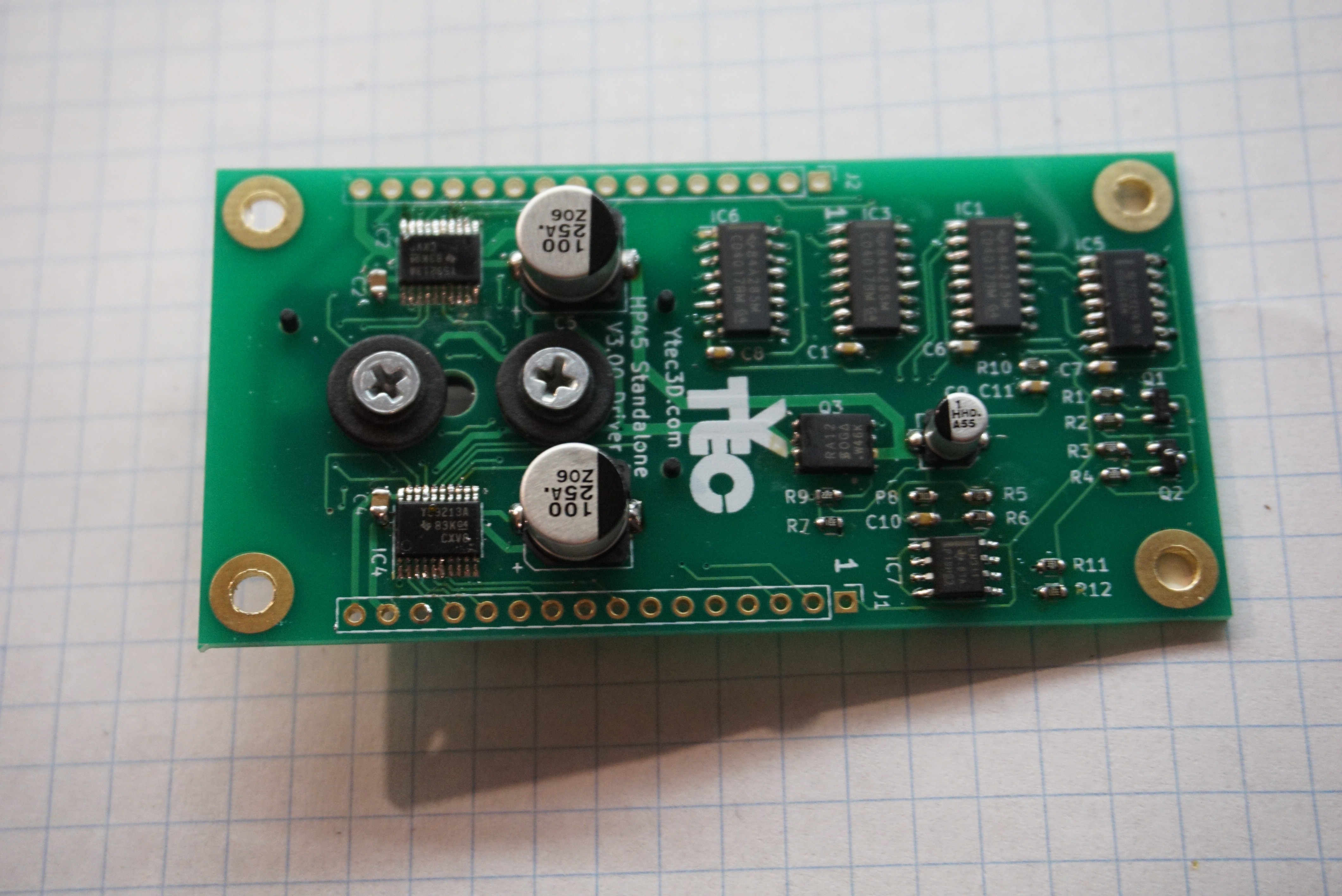 2x 16 pin female headers, 2.54mm (J1, J2)
 Solder the Teensy 3.2 to controller board. Here you can optionally solder female headers to the board. Be aware though that this will increase the height of the whole assembly to a point where it will not properly fit in Oasis.
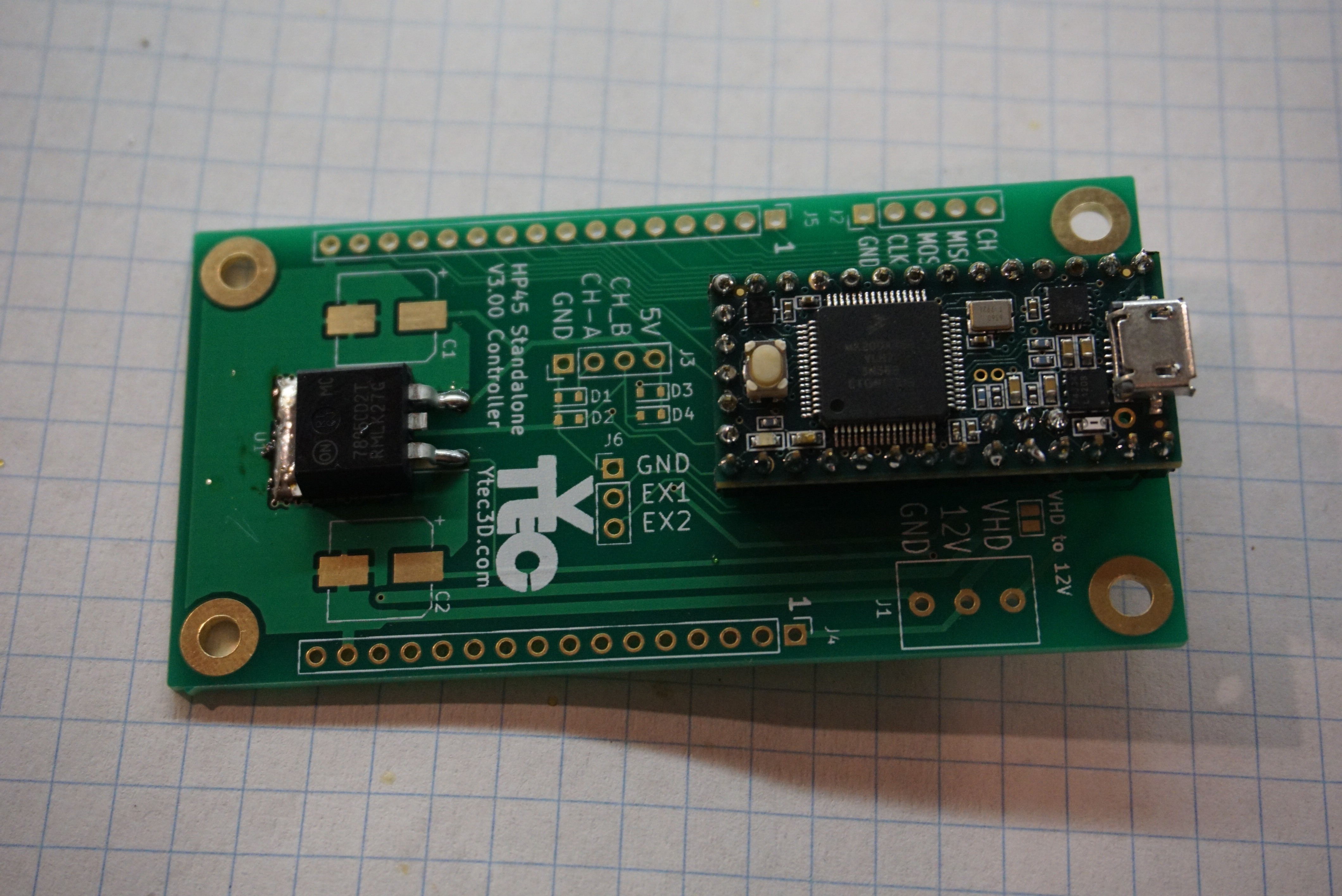
 Put boards together and enjoy.


Discussions
Become a Hackaday.io Member
Create an account to leave a comment. Already have an account? Log In.
How is the raspberry pi interfaced? Where can I get more information on this?
Are you sure? yes | no
I did some mistake and I try it without update v3.02 .. I fix it now . but I am taking
GTP:-C
after when I try to GTP
whay is the meaing of it?
Are you sure? yes | no
Solved .. that is hardware problem in controller card. Old controller card there are a mistake at Hen and Tsr.
If you swap HEN and TSR (cut the traces and add new wired) it should work.
Are you sure? yes | no