I spent the past weekend designing several PCB's. The number on the boards is 3.00, which suggests there are 2 more versions (there are). Both older versions have too many additional components. One is just expensive because of it, the other has given unknown issues that weren't there before. I decided to make a bare bones controller with only the essentials that have worked so far. All boards mentioned are 40x80mm, the smallest I can make the board and make it easily fit behind the printhead. Smaller is possible, but I nether want nor need that right now.
I will try to keep the Files updated when I publish logs. If I forget remind me. For now I will keep the files on my site until I figure out hop to properly use Github.
A download for the PCB's can be found here: https://ytec3d.com/oasis-download-page/
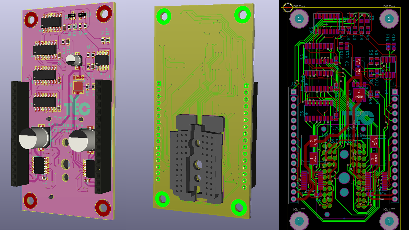
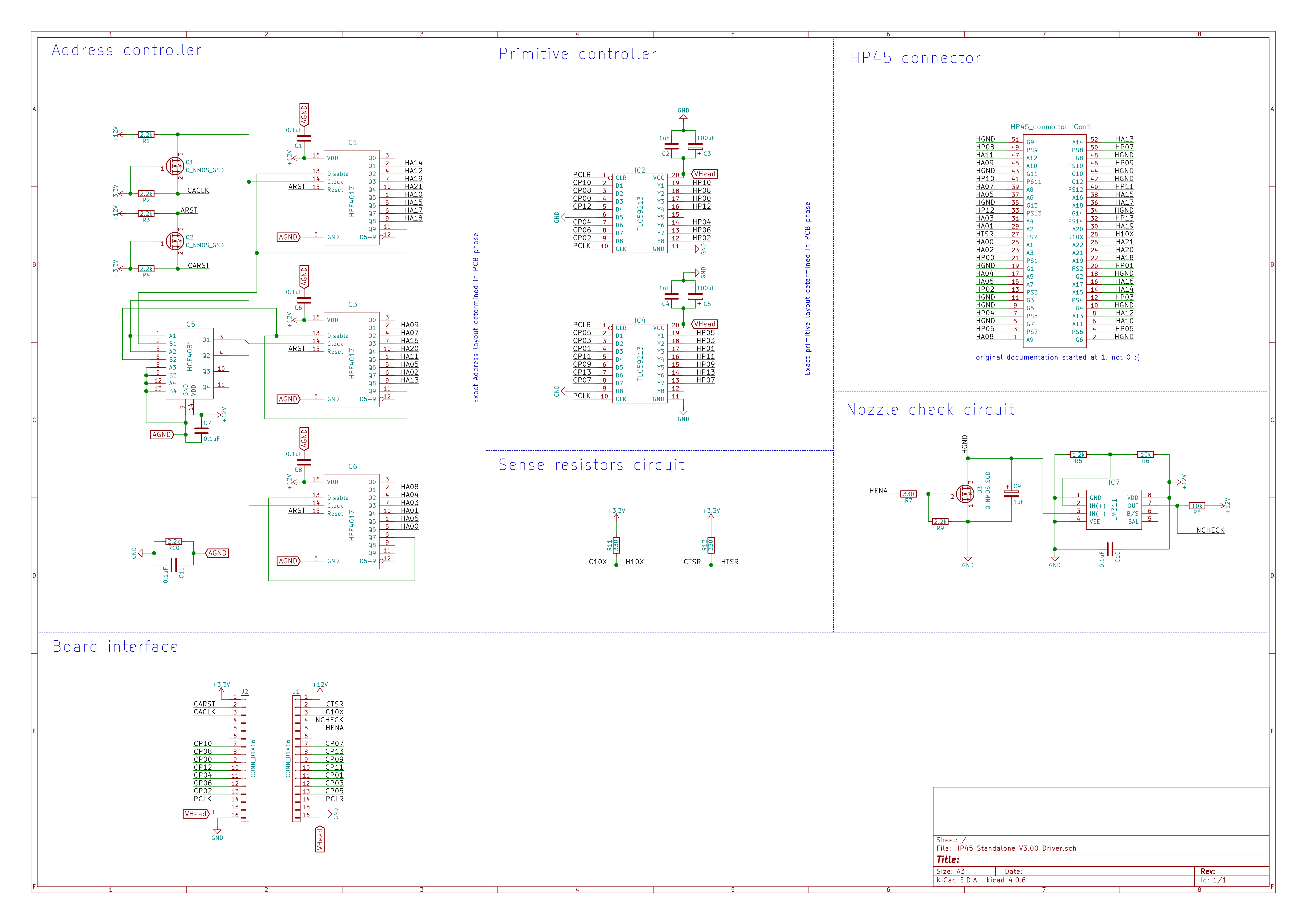
Driver board
The driver board hold all components that interface with the HP45. There is nothing new compared to the previous log, so I won't go into too much detail. The TLC59213's are the high side drivers used to power the primitives. I have experimented with double driver chips to solve some issues with the number of primitives that can fire at once. Because this did not seem to fix it, I have not included this. The 4017 and 4081 with level shifter is perhaps not the most elegant or compact. solution, but it has worked incredibly well so far. The nozzle test circuit also leaves room for improvement, but I first want to make this printer work, then make the circuit better.
The driver board interfaces with the controller through 2 16 pin headers. The power arrives on the controller board. This is also to easily add some specific features later.
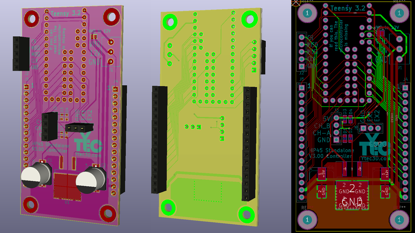
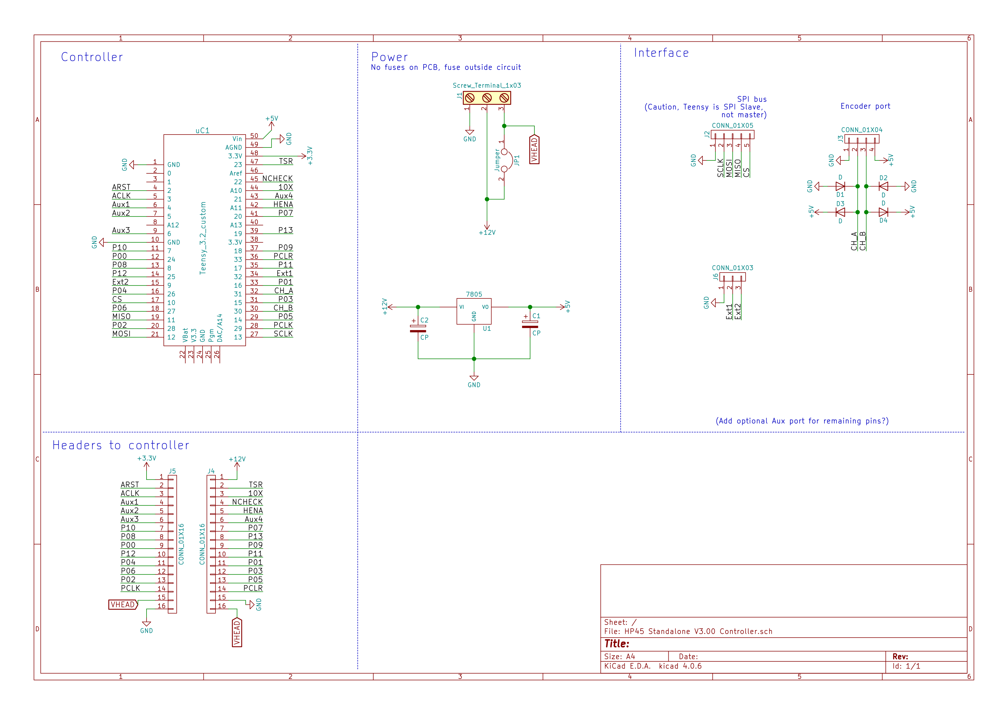
Controller board
The controller board holds a Teensy 3.2 right now. It can talk over SPI and USB serial through headers or USB port. Normal serial is not connected to the header and can be used, but is not on a header of it's own. The board has all Teensy I/O pins (including the ones on the back of the teensy) broken out to the 2x 16 pin headers. I am not using all these pins right now, but having them on the board might be useful to add stuff later. Also on the board is a 5V regulator to turn the 12V into 5V (So the teensy regulator does not have to struggle). Finally, there is a header for the encoder that is used to synchronize the printhead with the gantry.
Encoder strip used
The encoder used is the Avago HEDS-9740#150 with 150 lines per inch optical strip. I tried a normal encoder but this was way more compact. This stuff is normally used in inkjet plotters, so it should do well in my printer.
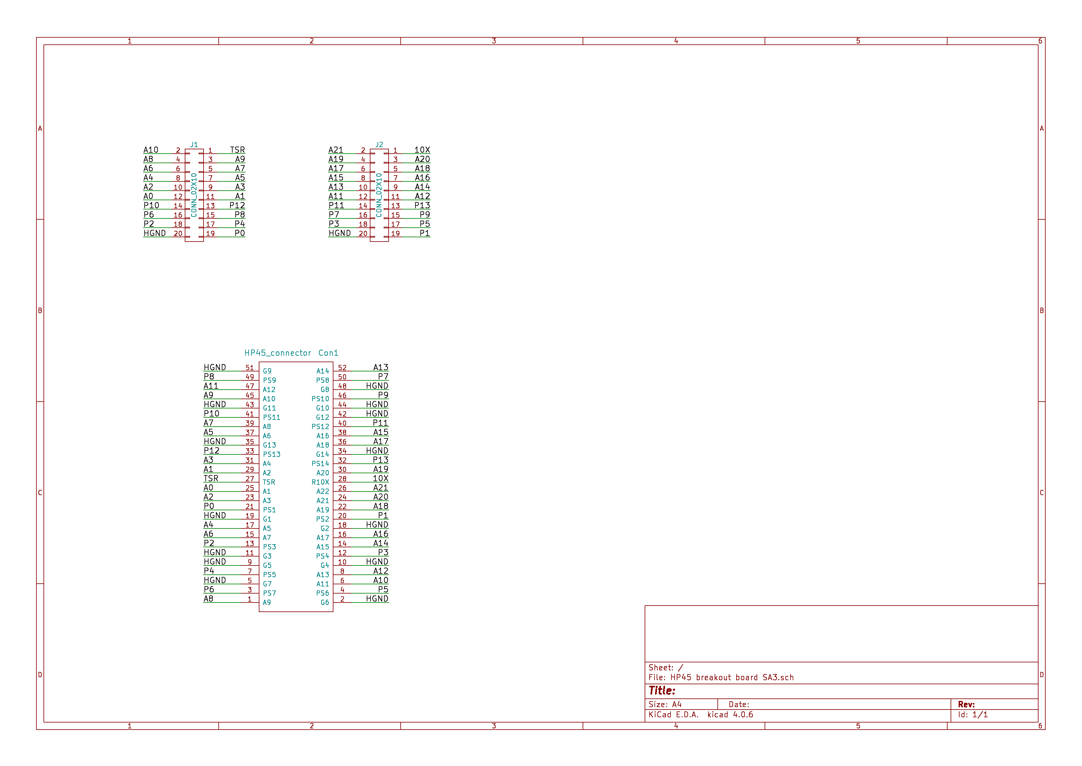
Breakout
While I was at it, I made a breakout board in the same size for future experiments. It directly breaks out all the high side pins to 2 2x20 headers. 1 ground on each header is included.
B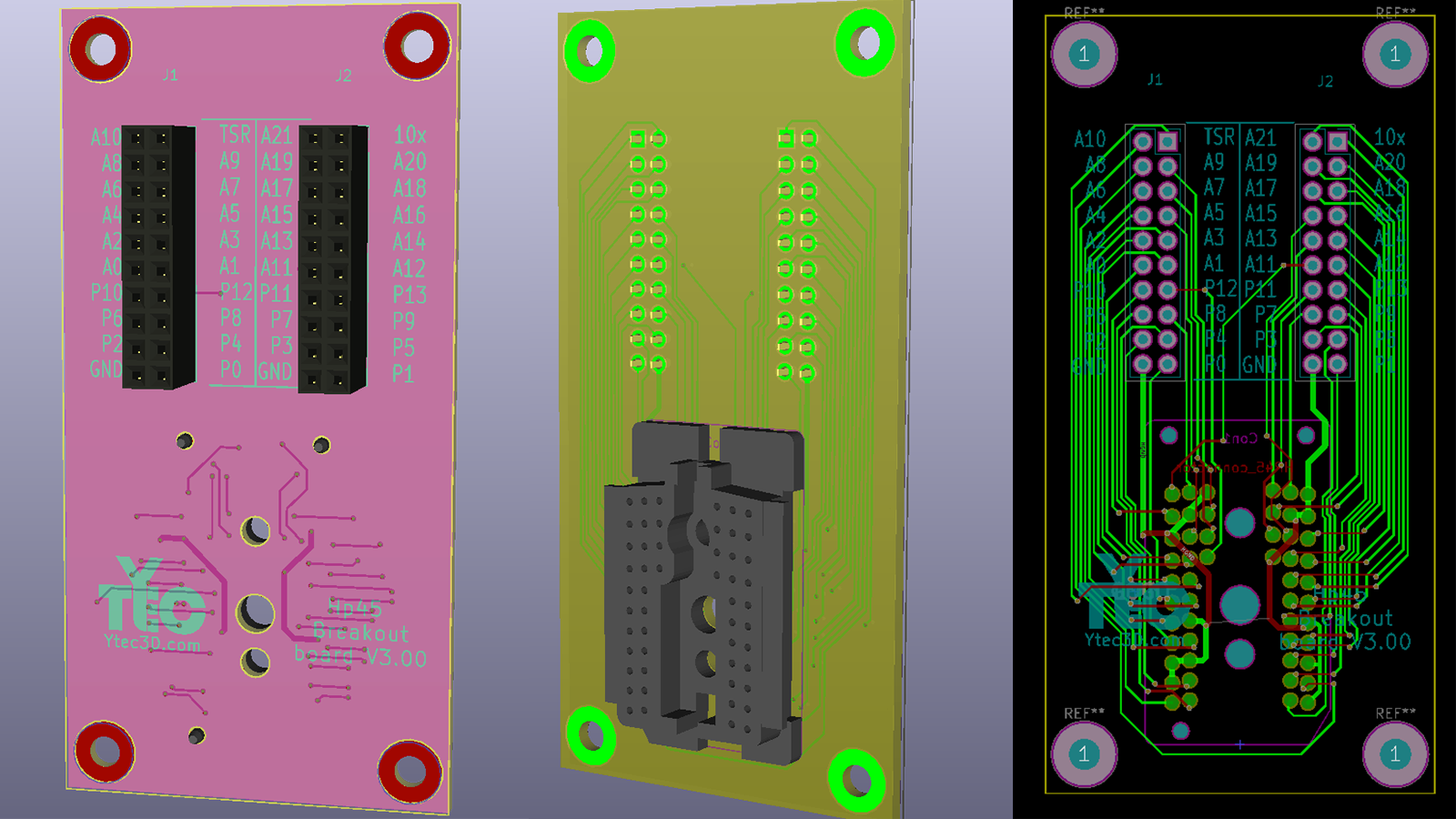
All PCB's will be reviewed until this weekend. After that a Batch of every PCB will be ordered.
Discussions
Become a Hackaday.io Member
Create an account to leave a comment. Already have an account? Log In.