Oasis would not be much without a frame and a gantry that moves the head. The last few weeks, while the PCB's are under the way, I have worked on the frame of Oasis. because 3D design has few milestones that would be log-worthy, it has been quiet. To reiterate, the design is done in Solidworks (2014). I would love to learn fusion 360 or something more open source at one point, but I am not going to learn it for a project of this scale. Solidworks is something I have available and I am good at.
Right now the frame, gantry and some printbed related parts are almost ready. I hope to be ordering the parts somewhere this or next week. The actual hoppers are not done yet. These can be added later and the first few months I can work without a hopper. All green parts are 3D printed and should be supportless.
The printer is designed around a few standard parts. The frame is made from 30x30mm and 30x60mm aluminium extrusion (Slot width 8mm, center hole M8). A lot of other 30mm aluminium extrusion should be compatible. The linear rails are Hiwin MGN12H. The timing belts are GT2, and the stepper motors are Nema 17. Most of these parts are fairly standard in 3D printing land. I also tried to keep as few bolt sizes as possible. Right now I have: DIN 912: M3x10, M3x20, M4x12, M4x20, M4x30, M6x12, (M6x16), M8x30; DIN 963: M3x10, M3x16, M4x16; DIN 7991: M6x12.
Printhead carriage
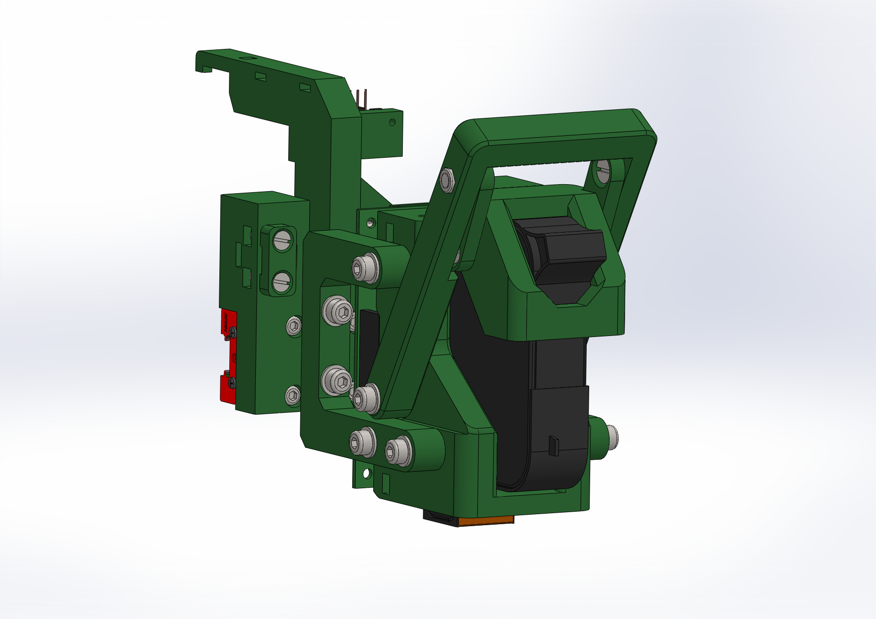

The printhead is arguably the most interesting part of this project. Right now I have the 3D printed carriage for the printhead and controller, and the frame and bearings to mount it to the gantry. The gantry moves in the Y-direction. The carriage is mounted to the gantry using 2 Hiwin linear bearings (MGN12H). To lock the printhead in place, I am using a latching mechanism that locks around the printhead when it is moved up. The big arm that reaches to behind the printhead is to mount the encoder and to pick up the cable
Gantry

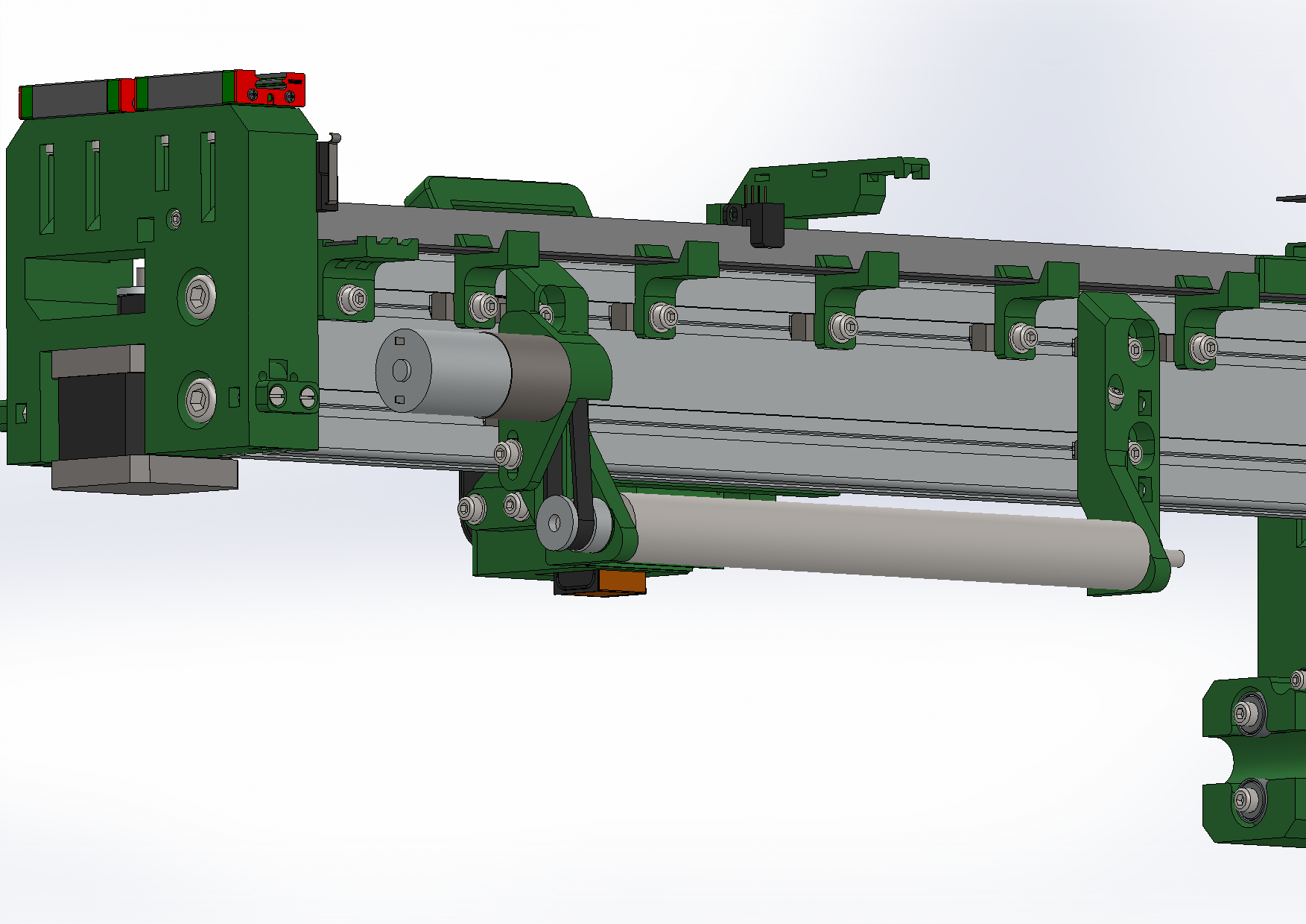
The gantry is the frame that moves in the printhead in the X-direction. The center of the gantry is a single 30x60 aluminium extrusion (from Misumi, but others should work too). On either end there are bearing blocks that allow the gantry to move in X, one using 2 linear rail carriages (fixed side), and one using a simple round rod (free side), not to over define the gantry too much. Both sides will have a timing belt. On the aluminium extrusion there is the guide for the carriage cable, and the encoder tape that the carriage uses. Also on the fixed side there is the motor that moves the carriage, both endstops and a cable pickup.
The spreader mounted on the back of the gantry is used to spread the powder from the feed hopper into the build hopper. It is a Misumi rotary shaft. This way I can get a part that is really accurate, but I will try to find an alternative for people without access to either a lathe or Misumi later (remind me if I forget).
Main frame
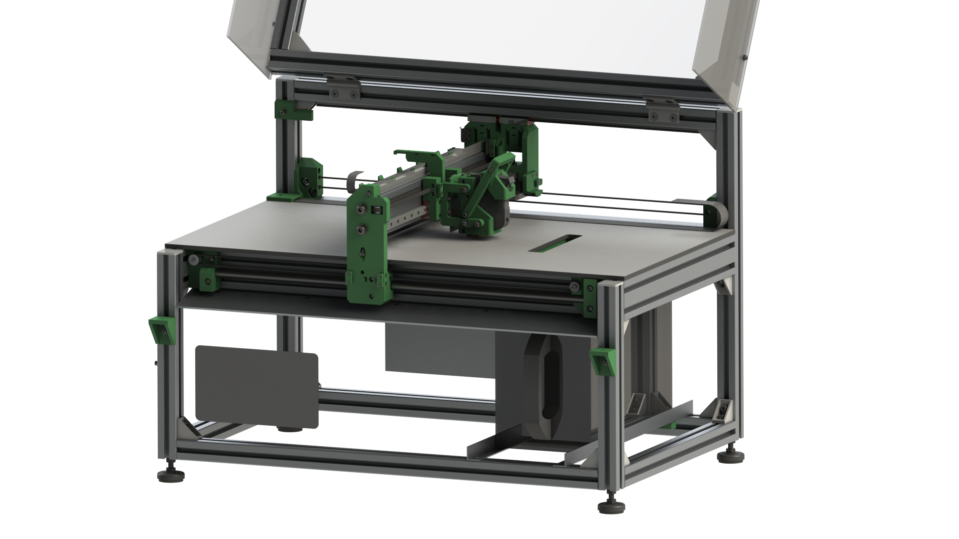
The Main frame holds all components and is made from 30x30 and 30x60 aluminium extrusion. I have considered making a frame from a sheet material, but I have done that 3 times now, and I have never been really satisfied with it. The frame has become a bit more complicated than I would have wanted, but for a prototype it is going to be fine.
To mount the gantry, there is a linear rail, mounted upside down on the back. It is this orientation to keep dust out of the rail. In the from is the 12mm round rod that supports the free side of the gantry. The free side rod is under the build surface to protect it from most of the dust. The belt for the X-direction is at the height of the free side. On the fixed side it goes up first, using a set of idler rollers.
A start has been made on the build surface. It will consist of a plate of HPL (or something else rigid 6mm'ish thick). At the end of the build surface is the opening where the excess powder will go. Beneath that opening, there is a bin that will catch the excess.
To cover the build area, there is a lid. This is also made of aluminium extrusions, and has either polycarbonate or acrylic sheets to cover the area.

That is all 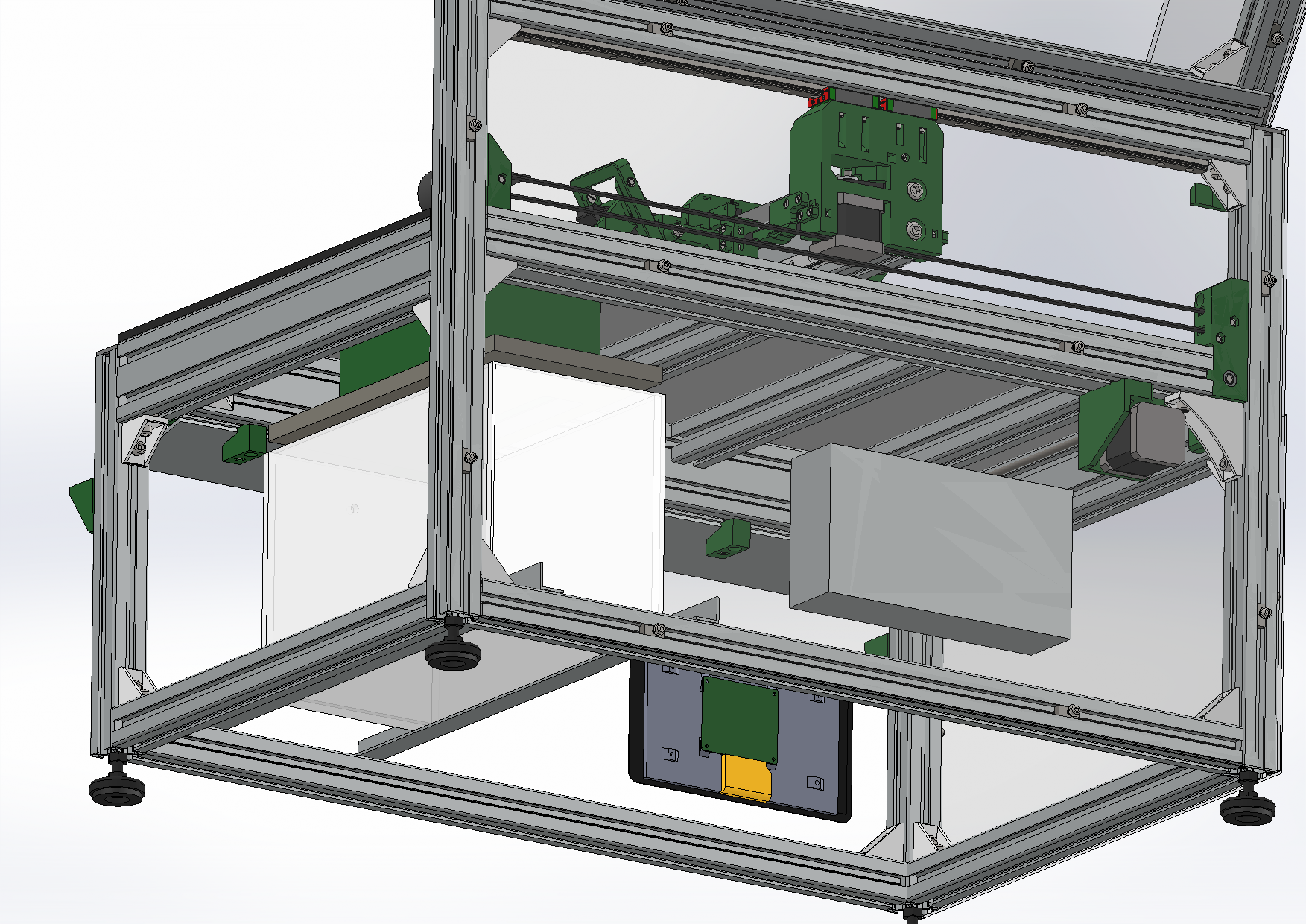
 That is all for now. My next update will either be when the parts for the frame start to arrive, or more likely when the PCB's arrive.
 (PS, the raw files for the frame will be added when I have ordered the frame. Then I will also have a proper bill of materials for the current frame. I will also try to add Step files of the 3D printed parts so other can use them as well)
Discussions
Become a Hackaday.io Member
Create an account to leave a comment. Already have an account? Log In.