The following procedures will be executed to transform voice commands into LED activity:
- Audio waves will be captured and amplified by the Sparkfun Electret Breakout board;
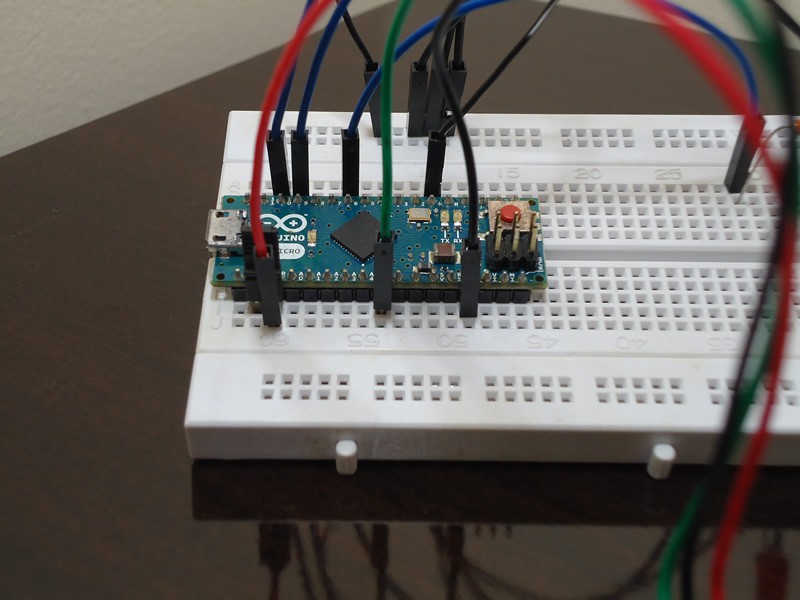
- The amplified signal will be digitalized and buffered in the Arduino using its analog-to-digital converter (ADC);
- The audio samples will be streamed to BitVoicer Server using the Arduino serial port;
- BitVoicer Server will process the audio stream and recognize the speech it contains;
- The recognized speech will be mapped to predefined commands that will be sent back to the Arduino;
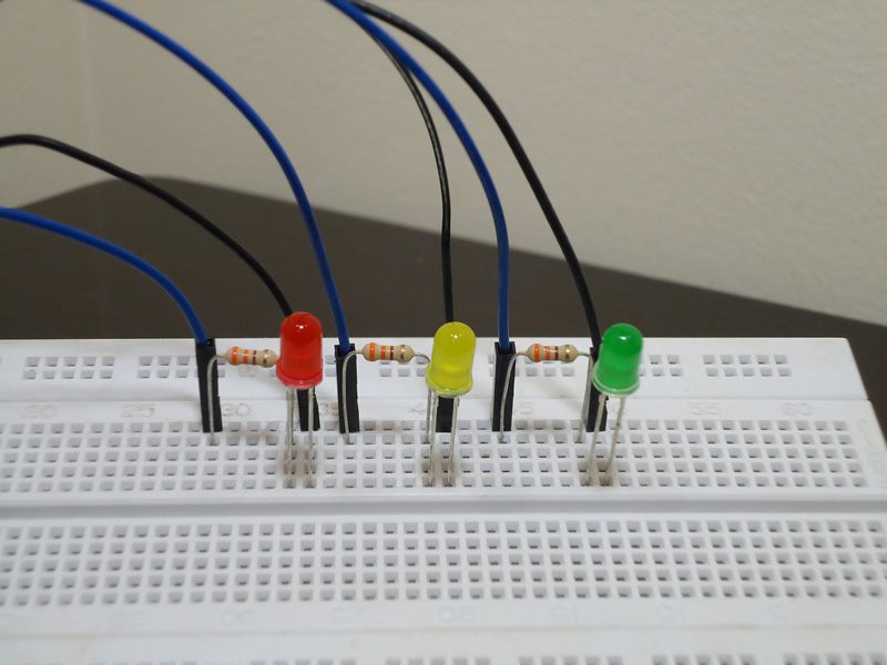
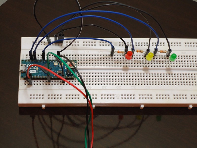
- The Arduino will identify the commands and perform the appropriate action.
The video below shows the final result of this project. Note in the video that BitVoicer Server also provides synthesized speech feedback. This speech feedback is defined in the server and reproduced by the server audio adapter, but the synthesized audio could also be sent to the Arduino and reproduced using a digital-to-analog converter (DAC). In my next project, I am going to try to use the Arduino DUE, one amplified and one speaker to reproduce the synthesized speech using the Arduino itself.
List of Materials:
- Arduino Micro (or any other Arduino board): ~U$ 20.00
- Sparkfun Electret Microphone Breakout: U$ 7.95
- BitVoicer Server 1.0: U$ 9.90
- Breadboard: ~U$ 10.00
- 3 x LEDs: ~U$ 1.00
- 3 x 330 Ohms resistors: ~U$ 0.75
- Jumper wires: ~U$ 0.30


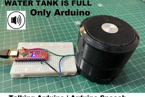
 spark buzzer
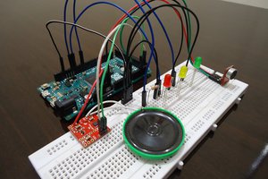
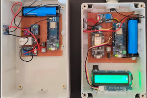
 Lithium ION