Project Brief:
Shoehorn a Raspberry Pi Zero into a NES controller. Load it up with RetroPie and wire up the buttons.
Requirements:
| # | Requirement | Justification | Status |
| 1 | System must be completely contained in a NES controller | A single-unit system is the main aim of the project | Success. External power + HDMI cables required. |
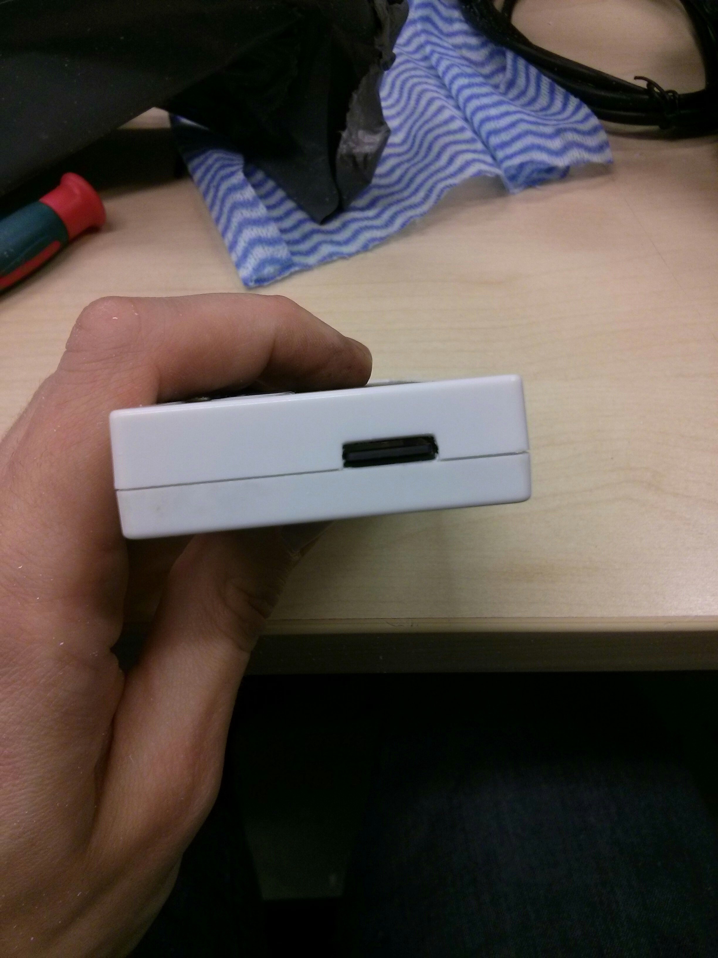
| 2 | All ports accessible | Need access for HDMI + Power. USB OTG port needs to be exposed for peripherals. SD card access required for software + ROM loading | Success. All ports accessible. |
| 3 | GPIO-connected controller buttons | USB OTG port needs to be available for other peripherals (e.g. Xbox controller), therefore the internal buttons must use GPIOs. All internal buttons need to be usable by the emulators. | Success. GPIO-keys based driver setup. |
| 4 | External status LED | So you can see what's going on | Success. bi-color red/green LED shows power + CPU activity |
| 5 | Minimal parts count | Easy to reproduce | Partial. External bi-color LED and resistors needed. Some laser-cut parts and epoxy |
| 6 | All parts easily removable | I always regret it when I glue something in. It always is a pain later | With the exception of the mounting hardware - Success. |
If you don't care about requirement 6, I would recommend generous helpings of hot glue instead of faffing around with bolts.
Method:
Using a real NES controller would be somewhat sacrilegious, so I grabbed a cheap USB one off ebay (£3.50 delivered!): http://www.ebay.co.uk/itm/USB-Classic-Gaming-Controller-Gamepad-For-Nintendo-NES-Windows-PC-Mac-Retro-Link-/381259815139?hash=item58c4db18e3:g:swIAAOSw3xJVVFa~
Obviously a Pi Zero is also required.
First observation is there's just enough room to fit in the Zero without needing to cut up the circuit board. This is good news.
The basic plan is:
- Determine basic location for Pi
- Add internal mounting method
- Cut holes for ports
- Test-fit
- Wire up LEDs
- Wire up buttons
- Mount LEDs and buttons
- Close
- Fix it in software
Mount the Pi:
The depth is just right for a 3mm piece of acrylic to sit the Pi on top of in the bottom half of the controller. So, let's draw and laser cut the appropriate shape and tap the holes for M3 bolts. The Pi's holes are actually M2.5, but who the hell has M2.5 bolts and taps?! So, drill out the Pi holes as well to take M3 bolts.
Next, it was necessary to shave down some of the internal wall of the case to get the Pi's ports close enough to the outside world. The outer wall in the Pi corner became pretty thin, but it's OK. After that's OK it's time to glue in the acrylic - Araldite seems to do the job.
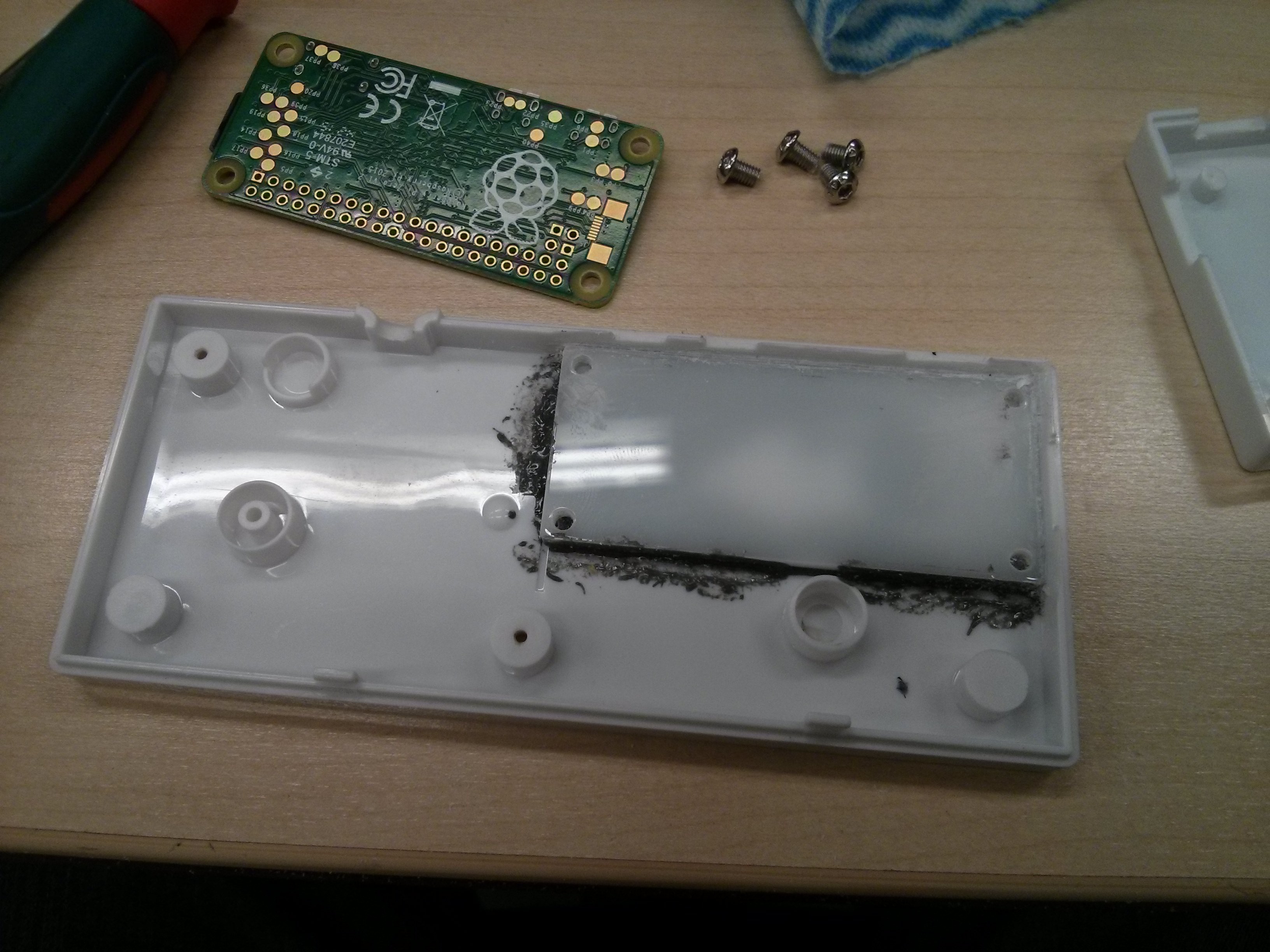
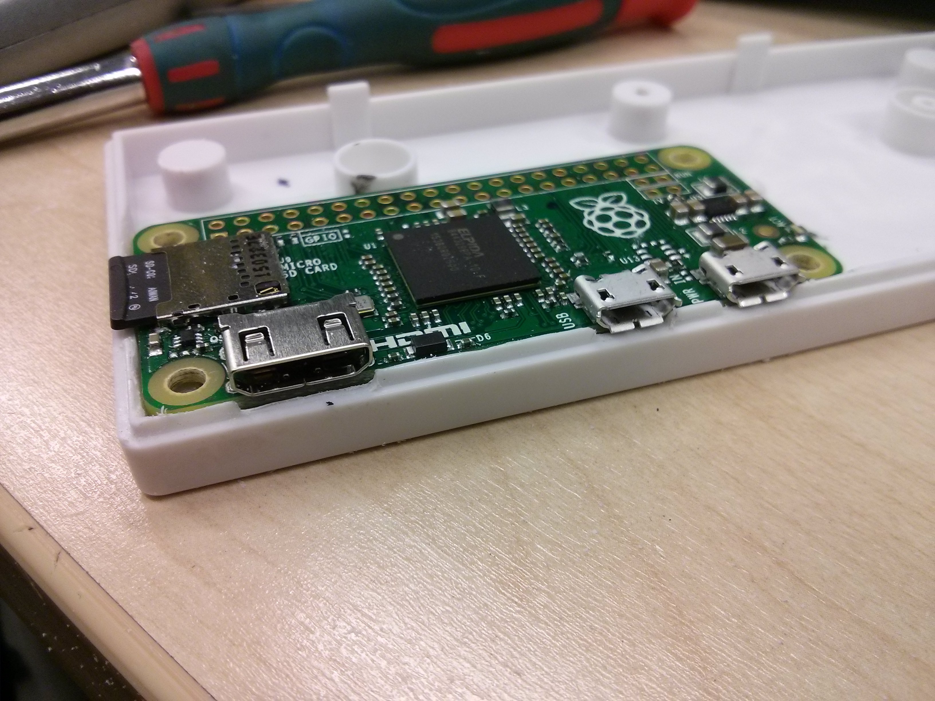
With the mount in place, it's time to start filing out the holes for the ports. Start on the bottom half of the controller, and get the Pi sitting flush with the acrylic mount.
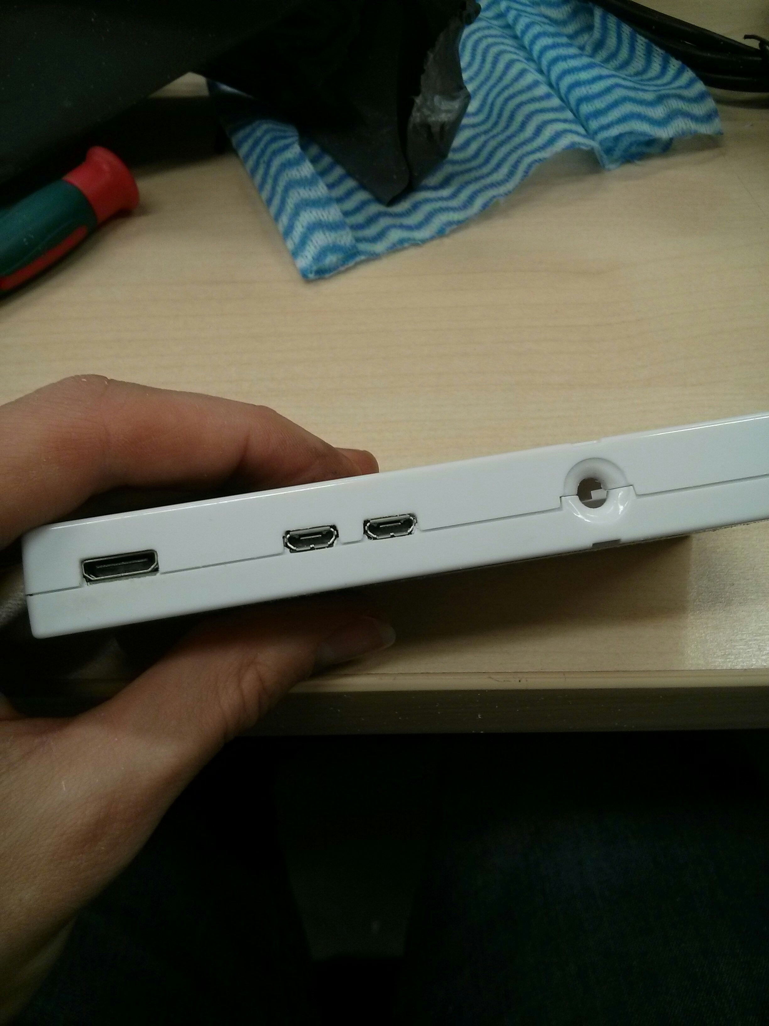
Then bolt the Pi in, and offer up the top-half. Mark the location of the ports and get to work filing them out in the top half too. Better to take this slowly so you get a nice end result. It's a slow job of filing a bit, putting it together, filing a bit more...
Also at this point I tweaked the old cable hole a little to take a 5mm LED (it's almost but not quite 5mm already, minor filing was required).
Hook up the LEDs:
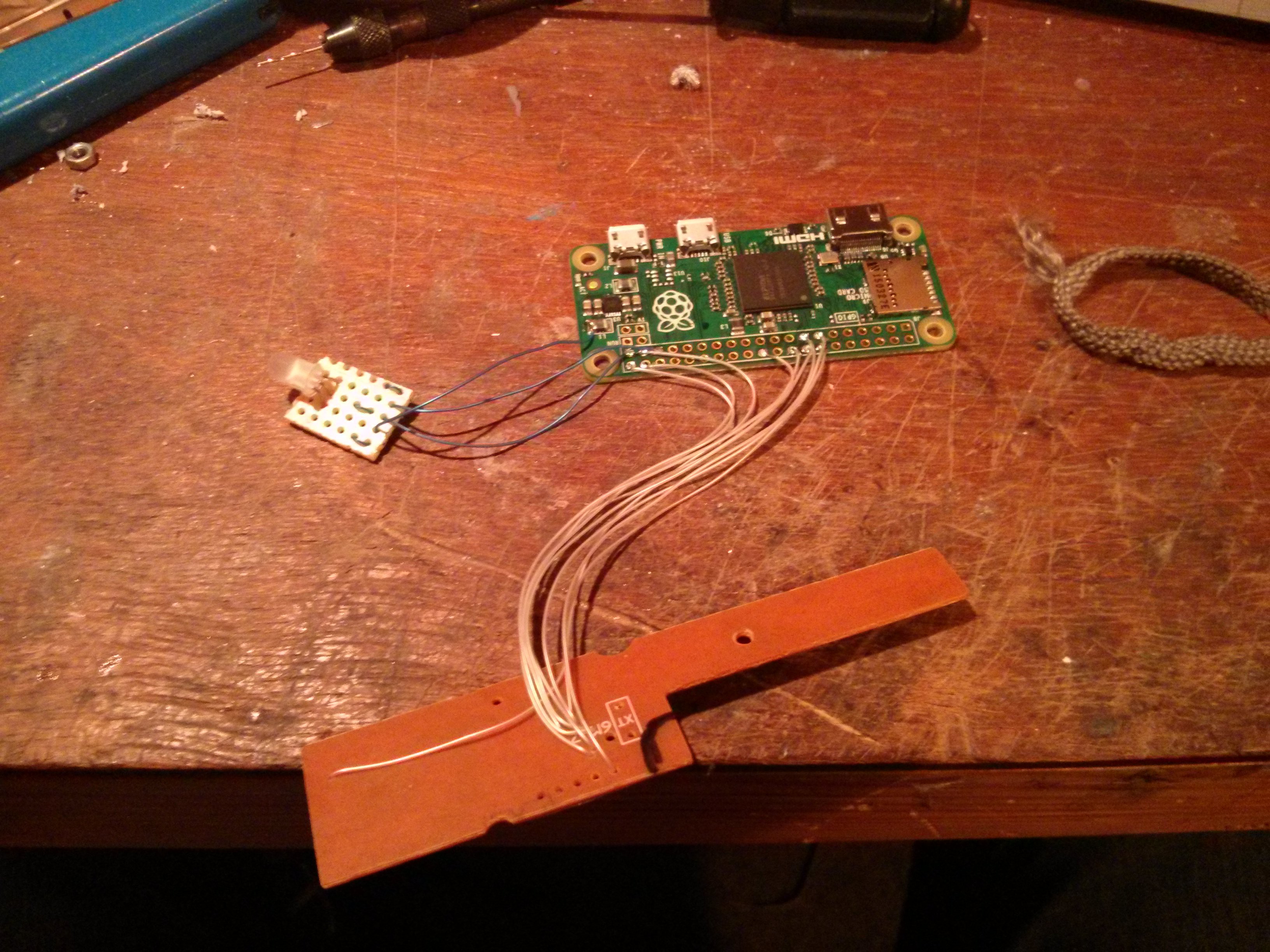
The LED-in-the-cable-hole looks pretty nifty, and it's useful too. I stuck it on a little bit of stripboard with some 0603 resistors. I wired the green LED directly to 3v3 and the red LED to GPIO19. It would be nice to not use up another GPIO, but I didn't trust my crappy iron to be able to pull off the on-board ACT LED without lifting a pad or two. If I need to use GPIO19 later I'll figure something out.
Hook up the buttons:
I want the buttons on GPIO to leave the USB OTG port available. If you don't just wire the USB cable to the Pi and call it done.
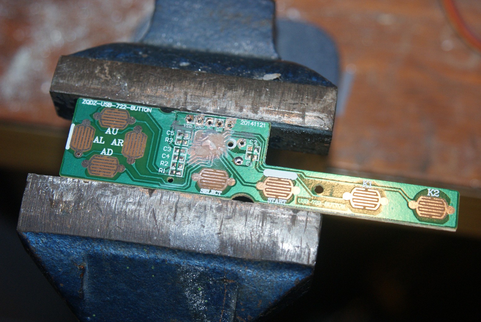
If you want to use GPIOs, you need to remove or disconnect the old chip. The old chip is a black blob of despair.

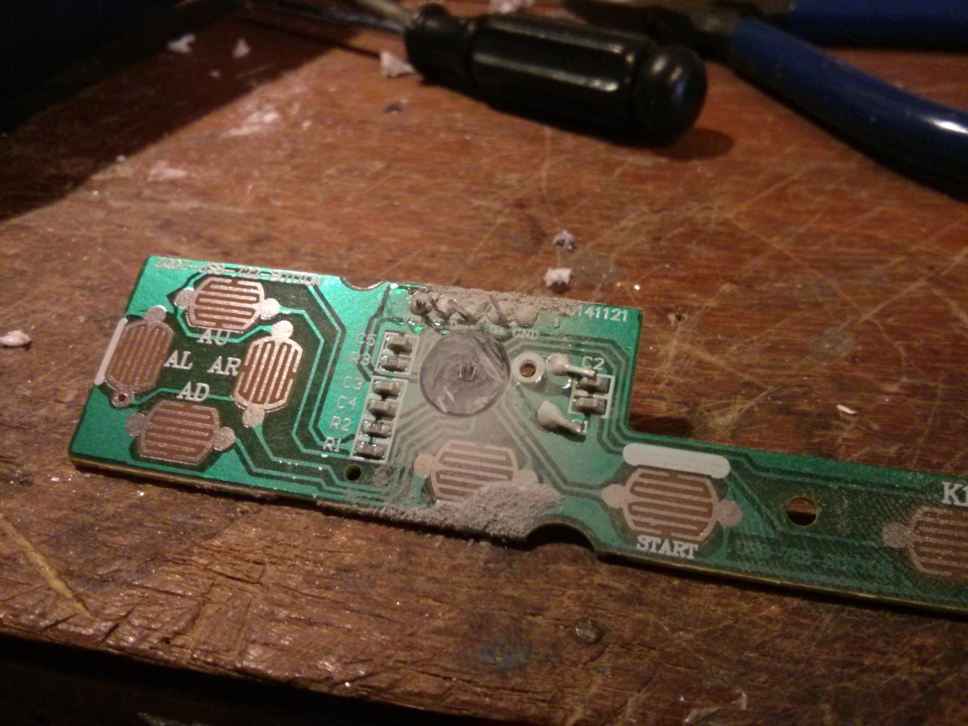
You need to figure out the button wiring. You could probably be smart and use the same wiring the USB controller did, but I wanted a nice simple software setup, so I hacked the board up to give me 8 separate common-cathode buttons. This takes up 8 GPIOs, but makes software way easier. I also took off all of the old components, we don't need them anymore.
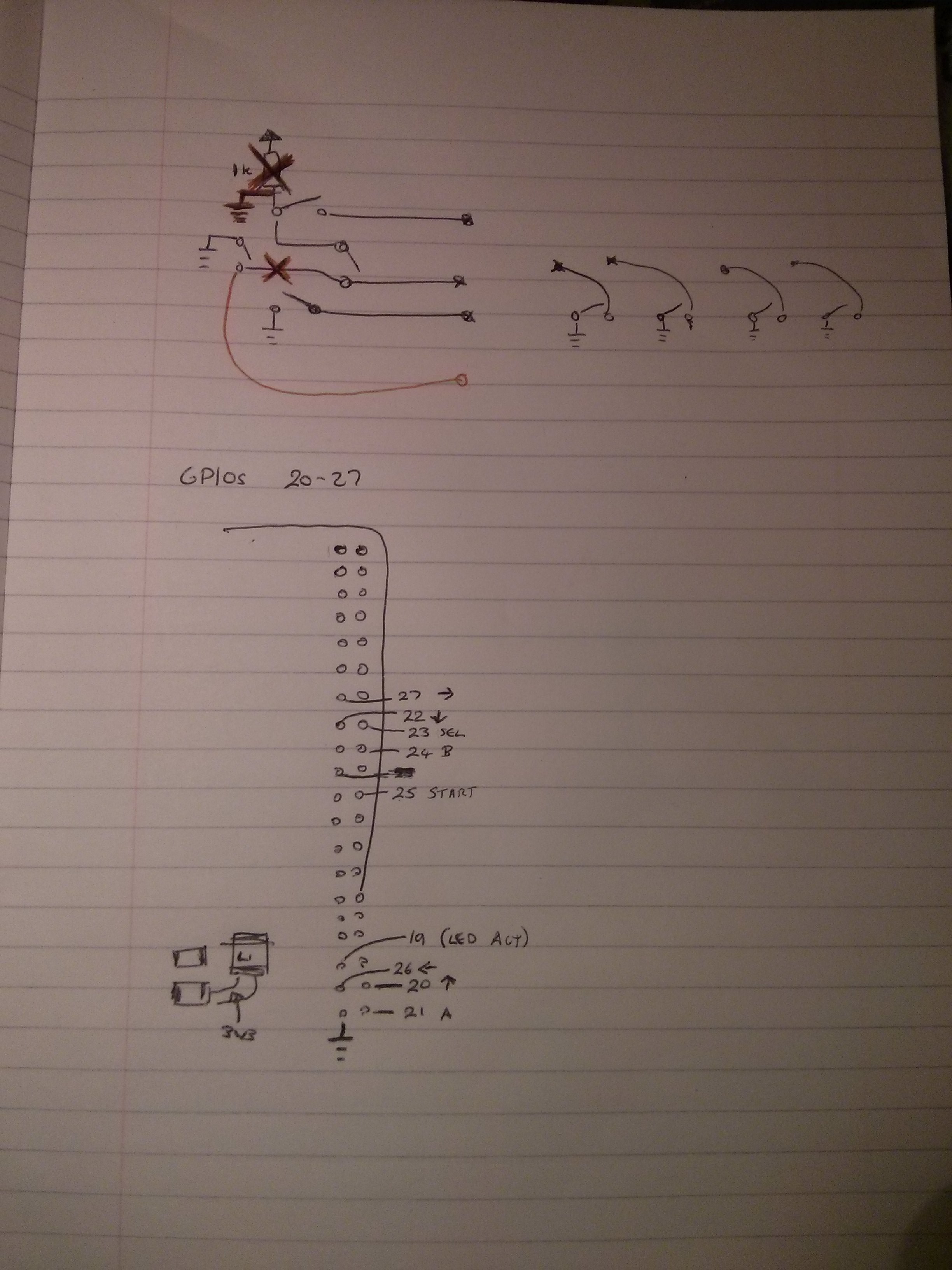
This is the closest I have to a schematic. The mods I made are coloured in red - short one line to ground, cut another.
I took a Dremel with a diamond tip to the black blob, trying not to destroy too much of the board in the process. This not only removes the pesky old controller, but gives us a little board real-estate to use later for wiring.
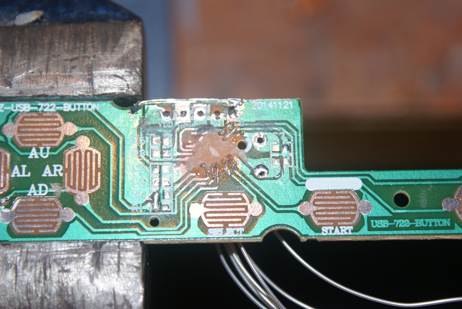
Then, drill some teeny tiny holes to use for wires. I used some 0.25mm solid-core Kynar wire I had lying around, and the smallest drill I had. I think the drill would have snapped if I put it in a power tool, so I drilled the holes by hand with a pin-vice.
With holes in the right places, very carefully expose a bit of copper on each trace you want, near its relevant hole, feed a wire through the hole and solder it to the trace. If you aren't careful the traces will lift, but you probably have 2 or 3 chances on each before you destroy enough trace to make it a problem. From now on, be careful with the wires. Might be a good idea to hot-glue them, but I didn't have any so I didn't.
Obviously you need to wire them to the Pi. I used GPIOs 20-27, just in-case I want to put a DPI screen on the rest of the GPIOs later. I was more concerned about not breaking my connections than connecting the buttons in any kind of order - so I just wired them in any old order and sorted out the mapping in software later.
Mount the LEDs and buttons:
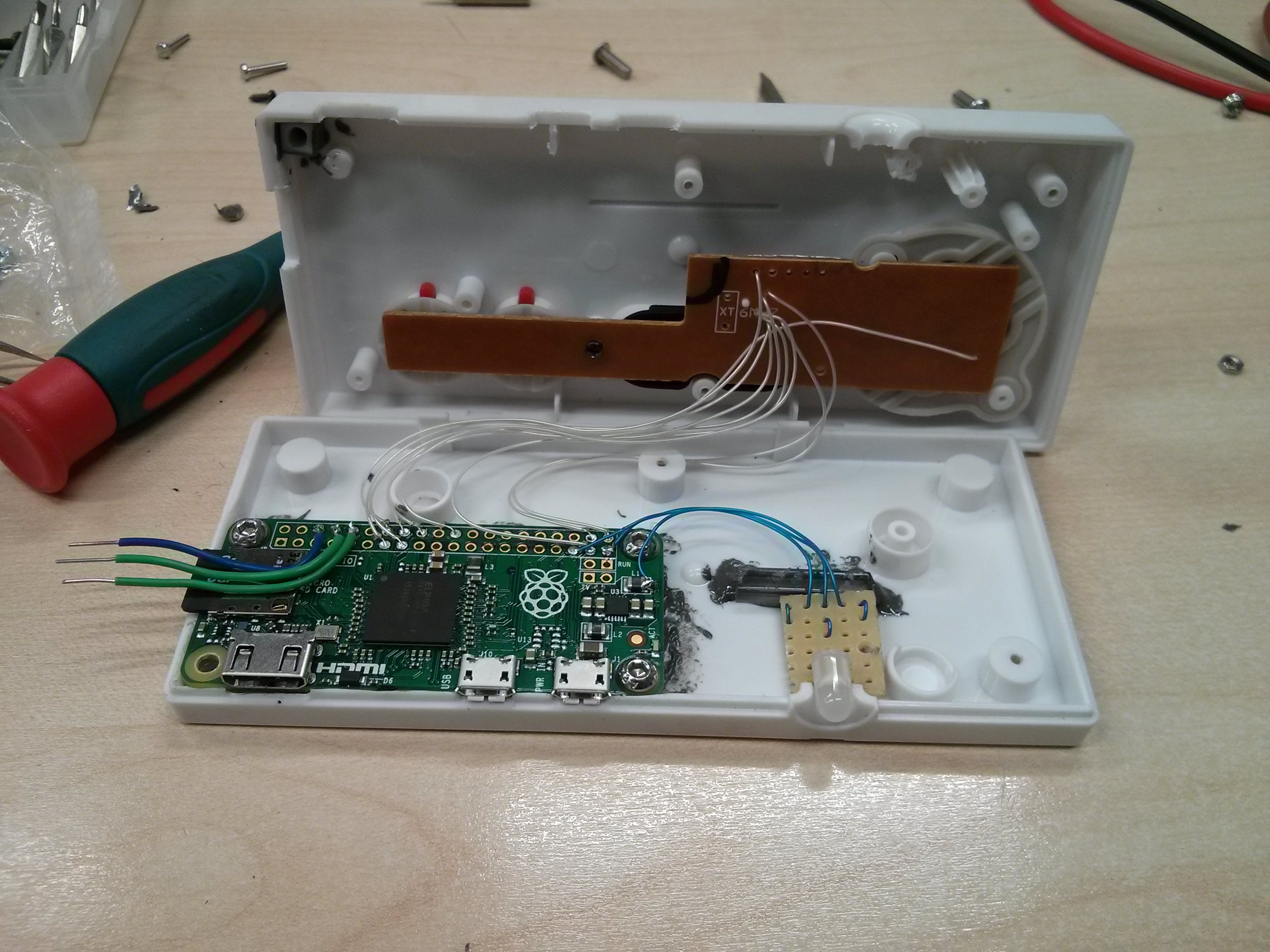
Mounting the buttons is easy. We didn't modify anything on the board, so it screws in like normal. Mounting the LEDs depends on whether you want them to be removable or not. If not, use hot-glue. If so, I glued in a piece of acrylic to hold the LEDs in the hole.
Close:
With any luck, everything should fit together nicely-nicely. We've removed some internal structure of the controller, so it probably won't hold itself together in the Pi-corner. I drilled through the bottom of the case in the outermost Pi mounting hole and glued in a plastic nut in the top half of the case, so I can bolt that corner of the controller together. It's a bit unsightly on the outside, but I can live with it.
The three fat wires are the serial console - useful for initial bring-up when I wasn't near a HDMI port.
Fix it in software:
The basis is going to be RetroPie: http://blog.petrockblock.com/retropie/ Go put that on your SD card.
My favourite part of this project is that I didn't have to write any real code! The whole thing can be configured with a device-tree overlay. Here's how it looks:
/dts-v1/;
/plugin/;

/ {
	compatible = "brcm,bcm2708";

	fragment@0 {
		target-path = "/";
		__overlay__ {
			gpio_keys {
				compatible = "gpio-keys";
				#address-cells = <1>;
				#size-cells = <0>;
				pinctrl-names = "default";
				pinctrl-0 = <&keypad_pins>;
				autorepeat;

				/*
				 * Buttons connected to GPIO 20-27
				 * Connected in a somewhat random order.
				 * Mapped to the default retroarch keys.
				 */
				button@1 {
					label = "Up";
					linux,code = <103>;
					gpios = <&gpio 20 1>;
				};
				button@2 {
					label = "A";
					linux,code = <45>; /* x */
					gpios = <&gpio 21 1>;
				};
				button@3 {
					label = "Down";
					linux,code = <108>;
					gpios = <&gpio 22 1>;
				};
				button@4 {
					label = "Select";
					linux,code = <54>; /* R-Shift */
					gpios = <&gpio 23 1>;
				};
				button@5 {
					label = "B";
					linux,code = <44>; /* z */
					gpios = <&gpio 24 1>;
				};
				button@6 {
					label = "Start";
					linux,code = <28>; /* Enter */
					gpios = <&gpio 25 1>;
				};
				button@7 {
					label = "Left";
					linux,code = <105>;
					gpios = <&gpio 26 1>;
				};
				button@8 {
					label = "Right";
					linux,code = <106>;
					gpios = <&gpio 27 1>;
				};
			};
		};
	};

	fragment@1 {
		target = <&gpio>;
		__overlay__ {
			keypad_pins: keypad_pins {
				brcm,pins = <20 21 22 23 24 25 26 27>;
				brcm,function = <0>; /* Input */
				brcm,pull = <2>; /* Pull-Up */
			};
		};
	};

	fragment@2 {
		target = <&leds>;
		__overlay__ {
			/*
			 * External LED to show CPU activity.
			 * Active-high, GPIO 19
			 */
			ext_act_led: act {
				label = "ext_act";
				linux,default-trigger = "cpu0";
				gpios = <&gpio 19 0>;
			};
		};
	};
};
What it basically does is set up the internal pull-ups on the button pins and set them as inputs, set up a gpio-keys device (turns GPIOs into keyboard events) and add an external LED which shows activity on CPU0.Compile that with your friendly device-tree compiler (that's out of scope for this project - try https://www.raspberrypi.org/documentation/configuration/device-tree.md), then copy it to your SD card (/boot/overlays) and add it in config.txt:dtoverlay=whetver-your-dtb-is.dtb
You can download a pre-compiled .dtb from the links section, but if you do then you need to make sure you wire the buttons in the same order I did! The source is available there too.
I mapped the buttons to the default RetroArch mappings (z, x, enter, shift, up, down, left, right) so I didn't need to change any config in RetroPie.Now if you reboot, the LED should do the CPU activity dance, and the buttons should show up as a keyboard. If either of these things are not true, check "dmesg" for clues, or try "sudo vcdbg log msg".
Your kernel/modules might not have gpio-keys installed. The latest Raspbian distro does, so you can copy kernel.img and /lib/modules/* from there into your RetroPie install if needed.
Play!
OK that's it. Now you should be able to set up RetroPie to let you use the controller in the emulators. You might find it useful to plug a real keyboard into the OTG port until you get it set up right. I haven't figured out how to set up hot keys yet so I can return to the menu using the NES controller. If someone knows how to do that please comment!
Of course, because the OTG port is there you can plug in a different (additional? 2 player?!) controller if 2 buttons is too limiting (yo dawg... I heard you like controllers...)