 Ted Yapo
The goal of this project is an inexpensive module for interference-free proximity sensing. IR light is very useful for both sensing and remote control, but can be interference-prone. I have a remote-controlled lamp, for instance, that will respond to my Roku remote. More subtle is the degradation of range that can happen when multiple IR devices operate in the same environment, even though they may use different carrier frequencies. There are no FCC rules governing IR, so every designer is free to use whatever modulation scheme or frequency they wish. You might not see it, but it's the Wild West between 750 and 1100nm in your house.
Now, we are starting to add robots into this environment, often using sensors in these same IR wavelengths. When available sensors bother to avoid interference, they sometimes use short pulses of light (e.g. Vishay sensors), but this is not necessarily scalable to many sensors operating continuously. Additional techniques include polling sensors repeatedly to reject spurious detections. These techniques are limited in the amount of interference they can eliminate, and multiple sensors operating simultaneously may not be a design goal.
I envision using a direct sequence spread spectrum modulation technique to reduce the probability of generating or receiving interference for IR sensors. Additionally, these same techniques might be applied to communications.
Basic Idea
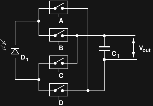
The block diagram shows the basic idea, although several implementations are possible.
Transmit
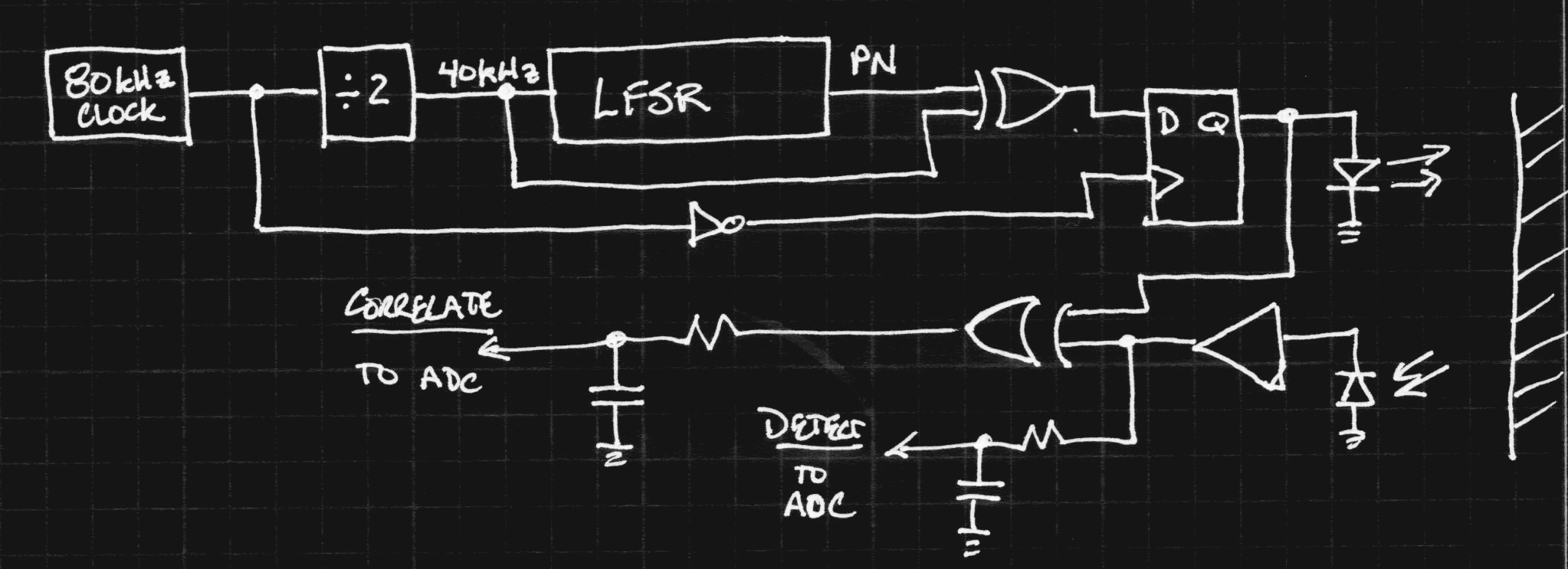
The top of the diagram is the transmit chain. An 80 kHz clock is divided by two to yield 40 kHz. The 40 kHz clock is fed into a linear-feedback shift register (LFSR) to generate a pseudo-noise (PN) sequence. An important property of these sequences is that their autocorrelation function has a single peak - in the simplest of terms, it's difficult to mistake other signals for the one you've generated. The pseudo-random bit-stream is then multiplied by the original 40 kHz clock in the upper XOR gate, and the result is registered in a D-flop to avoid runt pulses. The result is a spreading of the 40 kHz signal to cover a wider bandwidth.
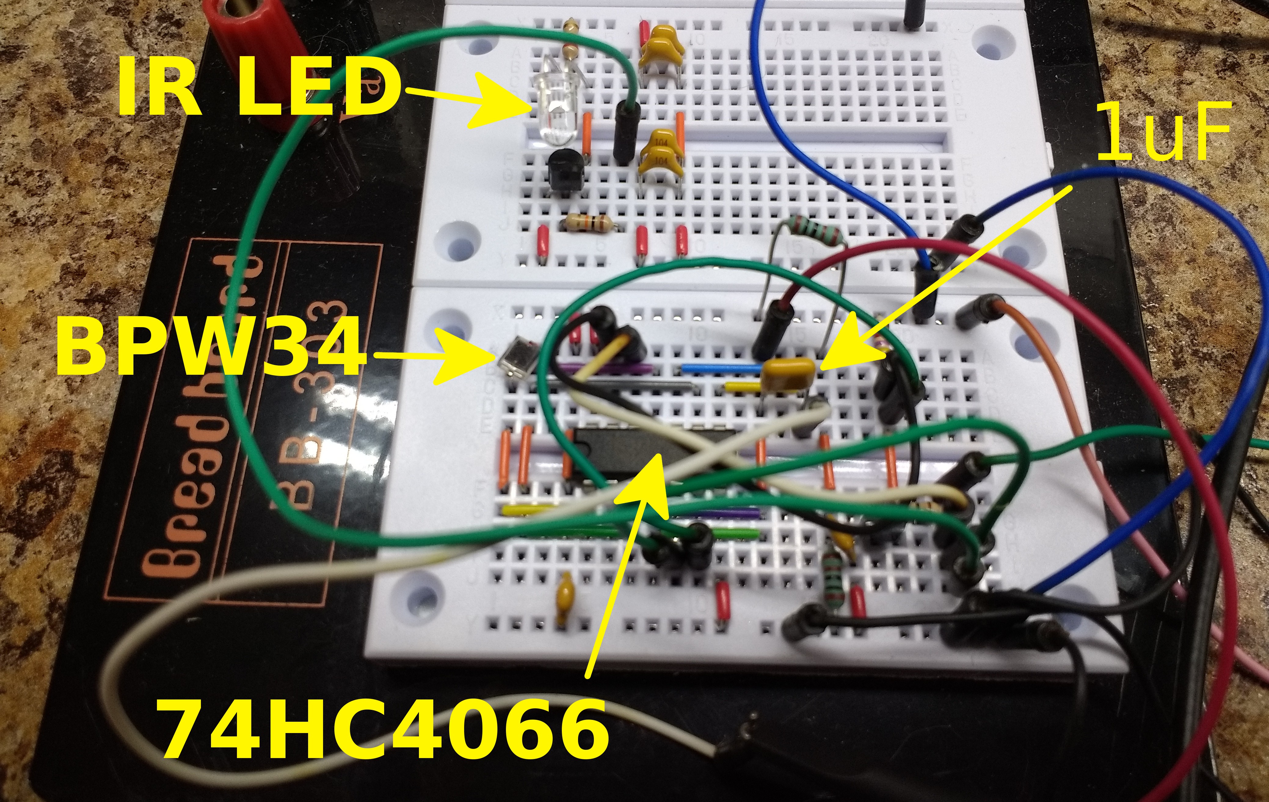
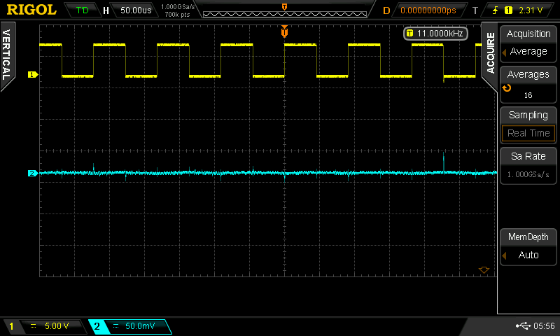
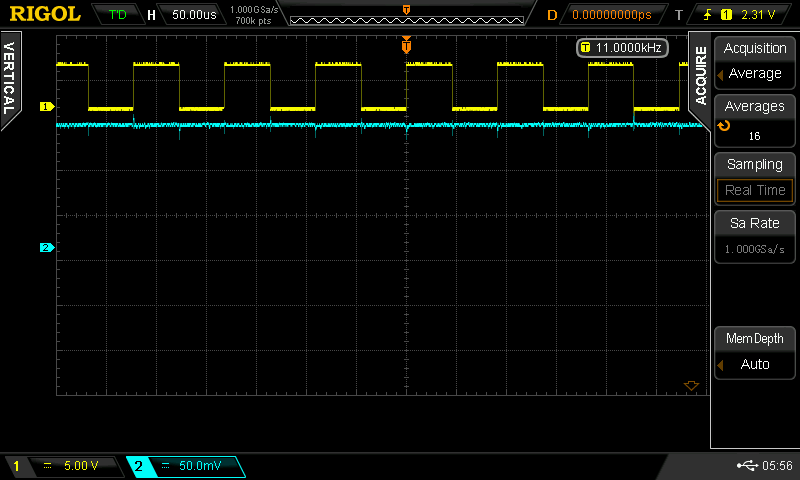
I happened to have a hardware implementation of this modulation scheme already, having built one as the RF exciter for #The Diode Clock.. While it is normally used int the MHz range, it works fine at 40 kHz, too, so I gathered some test data with it. Here are some waveforms I captured:
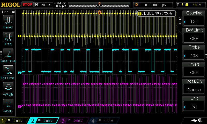
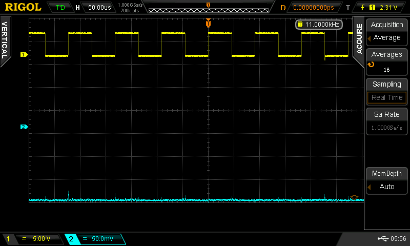
The yellow trace is the un-modulated 40 KHz signal, the cyan the pseudo-random output of the LFSR, and the magenta the modulated output. A zoom-in shows the output in better detail:
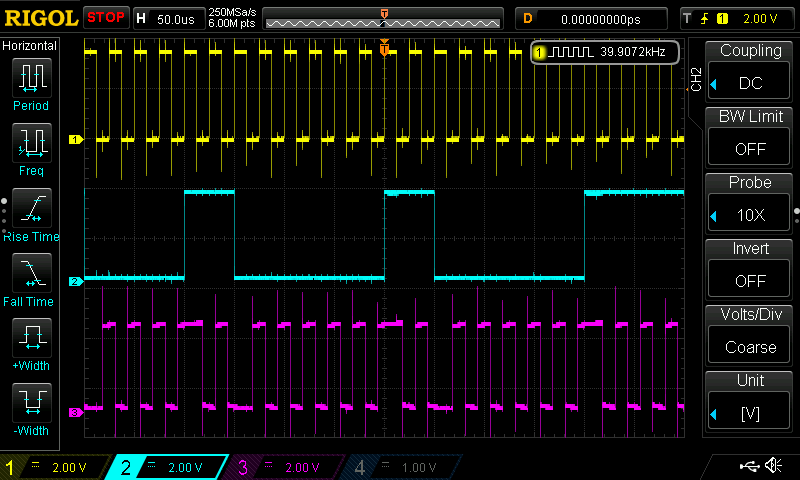
You can see that the PN sequence is selecting the phase of the 40 kHz carrier. An important property of this sequence is that it can only go so long without a transition, like Manchester encoding. This is important for AC-coupled transmission, so the switching threshold can be tracked accurately.
The hardware I had available uses a 15-stage LFSR, so can generate uniform runs of up to 15 clocks. Since most consumer IR sensors seem to respond to around 6 cycles of 40 kHz IR, the final LFSR may need to be somewhat shorter. On the other hand,this document points out that for any LFSR, half the runs are of length 1, one fourth are of length 2, one eighth of length 3, etc. So only 1/32 of them are of length 6 or greater, which may allow longer sequences.
The result is best visualized with a spectrum analyzer:
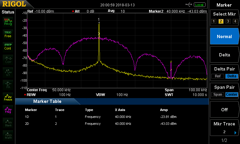
In this case, the yellow trace is the un-modulated 40 kHz signal, while the magenta is the output. You can see that the energy has been spread across a range of frequencies, with the first zeros at 20 kHz and 60 kHz. At this resolution bandwidth...
Read more »


 Lukas Koch aka Ast
 Bud Bennett
 Evangelos Petrongonas
Interesting! May be I could integrate this into my project when finished :)