 Ted Yapo
The goal of this project is an inexpensive module for interference-free proximity sensing. IR light is very useful for both sensing and remote control, but can be interference-prone. I have a remote-controlled lamp, for instance, that will respond to my Roku remote. More subtle is the degradation of range that can happen when multiple IR devices operate in the same environment, even though they may use different carrier frequencies. There are no FCC rules governing IR, so every designer is free to use whatever modulation scheme or frequency they wish. You might not see it, but it's the Wild West between 750 and 1100nm in your house.
Now, we are starting to add robots into this environment, often using sensors in these same IR wavelengths. When available sensors bother to avoid interference, they sometimes use short pulses of light (e.g. Vishay sensors), but this is not necessarily scalable to many sensors operating continuously. Additional techniques include polling sensors repeatedly to reject spurious detections. These techniques are limited in the amount of interference they can eliminate, and multiple sensors operating simultaneously may not be a design goal.
I envision using a direct sequence spread spectrum modulation technique to reduce the probability of generating or receiving interference for IR sensors. Additionally, these same techniques might be applied to communications.
Basic Idea
The block diagram shows the basic idea, although several implementations are possible.
Transmit
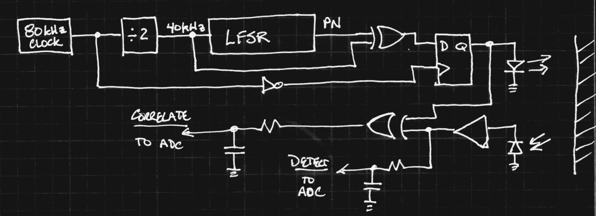
The top of the diagram is the transmit chain. An 80 kHz clock is divided by two to yield 40 kHz. The 40 kHz clock is fed into a linear-feedback shift register (LFSR) to generate a pseudo-noise (PN) sequence. An important property of these sequences is that their autocorrelation function has a single peak - in the simplest of terms, it's difficult to mistake other signals for the one you've generated. The pseudo-random bit-stream is then multiplied by the original 40 kHz clock in the upper XOR gate, and the result is registered in a D-flop to avoid runt pulses. The result is a spreading of the 40 kHz signal to cover a wider bandwidth.
I happened to have a hardware implementation of this modulation scheme already, having built one as the RF exciter for #The Diode Clock.. While it is normally used int the MHz range, it works fine at 40 kHz, too, so I gathered some test data with it. Here are some waveforms I captured:
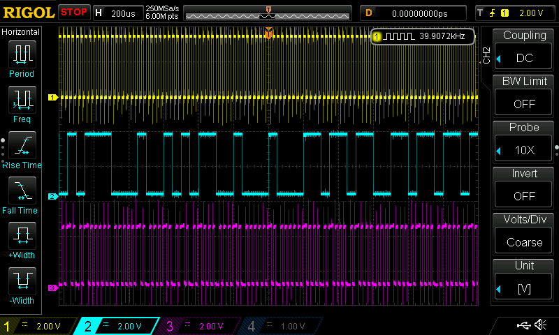
The yellow trace is the un-modulated 40 KHz signal, the cyan the pseudo-random output of the LFSR, and the magenta the modulated output. A zoom-in shows the output in better detail:
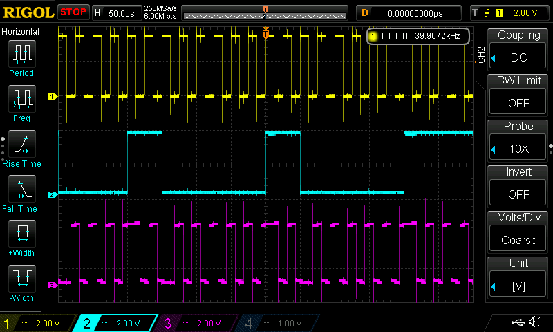
You can see that the PN sequence is selecting the phase of the 40 kHz carrier. An important property of this sequence is that it can only go so long without a transition, like Manchester encoding. This is important for AC-coupled transmission, so the switching threshold can be tracked accurately.
The hardware I had available uses a 15-stage LFSR, so can generate uniform runs of up to 15 clocks. Since most consumer IR sensors seem to respond to around 6 cycles of 40 kHz IR, the final LFSR may need to be somewhat shorter. On the other hand,this document points out that for any LFSR, half the runs are of length 1, one fourth are of length 2, one eighth of length 3, etc. So only 1/32 of them are of length 6 or greater, which may allow longer sequences.
The result is best visualized with a spectrum analyzer:
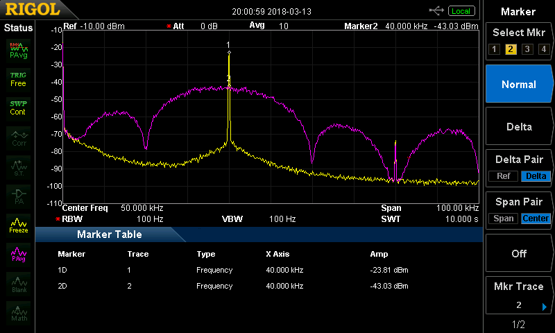
In this case, the yellow trace is the un-modulated 40 kHz signal, while the magenta is the output. You can see that the energy has been spread across a range of frequencies, with the first zeros at 20 kHz and 60 kHz. At this resolution bandwidth (100 Hz), the spread signal is down 20 dB (1% of the power) from the un-modulated carrier.
The correlation properties of the PN sequence should prevent modules from interfering with each other, while the bandwidth spreading should prevent them from interfering with other devices. Of course, the extent of the improvement in both cases will have to be measured.
Receive
In the receive chain (bottom), the signal from a photodiode is amplified, then mixed with the transmitted signal in a second XOR gate. Where both signals are the same, the output is low, while differing signals yield a high output. By low-pass filtering the output, a measure of the similarity of the transmitted and received signals is obtained. This value is read by an ADC to be thresholded inside the module. With just this single input, there is a chance of missed detections if the input is swamped by noise, however: this condition will produce a high output from the XOR gate, just as if no signal had been received. To avoid this case, the raw input signal is also low pass filtered and fed to a second ADC channel. This channel can be used to detect situations where a signal is received, but does not correlate with what was transmitted.
My current thought about the analog front end for the receiver is to use a Vishay VSOP98260. This IC is intended as a pre-amplifer for learning remotes. As such, it does not contain the narrow bandwidth filter (36, 38, or 40 KHz) normally found in remote-control front ends. The datasheet lists the frequency range as 20 kHz to 60 kHz, which happily coincides with the main lobe of the spectrum generated above (I wonder how that worked out so well :-)
One concern I have about using this part is the non-linearity. The IC "squares-up" the signal, producing logic-level outputs. This forces the design to perform the mixing/correlation in the digital domain, which isn't optimal from a receiver perspective. It remains to be seen how limiting this will be.
Alternative Receiver
I originally envisioned the receiver as a transimpedance photodiode amplifier followed by a mixer made from CMOS switches. Depending on the performance of the Vishay part, I may return to this idea if needed.
One crazy idea I've had is to modulate the VSOP98260's power supply. Depending on the supply rejection, it may be possible to mix the signal in the analog domain within the IC with this method. It's clearly a hack, and a long-shot one at that, but it's worth a few minutes at the bench to see what happens.
Implementation
Although it looks like a lot of hardware to put on a module, most of the system can be implemented on a PIC MCU. The current thought is a PIC16F1508. The entire transmit chain can be easily written in software, while the configurable logic cell (CLC) module can implement the XOR gate required in the receiver. The MCU comes with a 10-bit ADC which is plenty for the two analog channels required. The PIC also has SPI and I2C slave peripherals for communication with end-user systems.
What's Next
Watch the build logs to see how this project progresses.