 Ted Yapo
My original plan for a front-end was something like this:
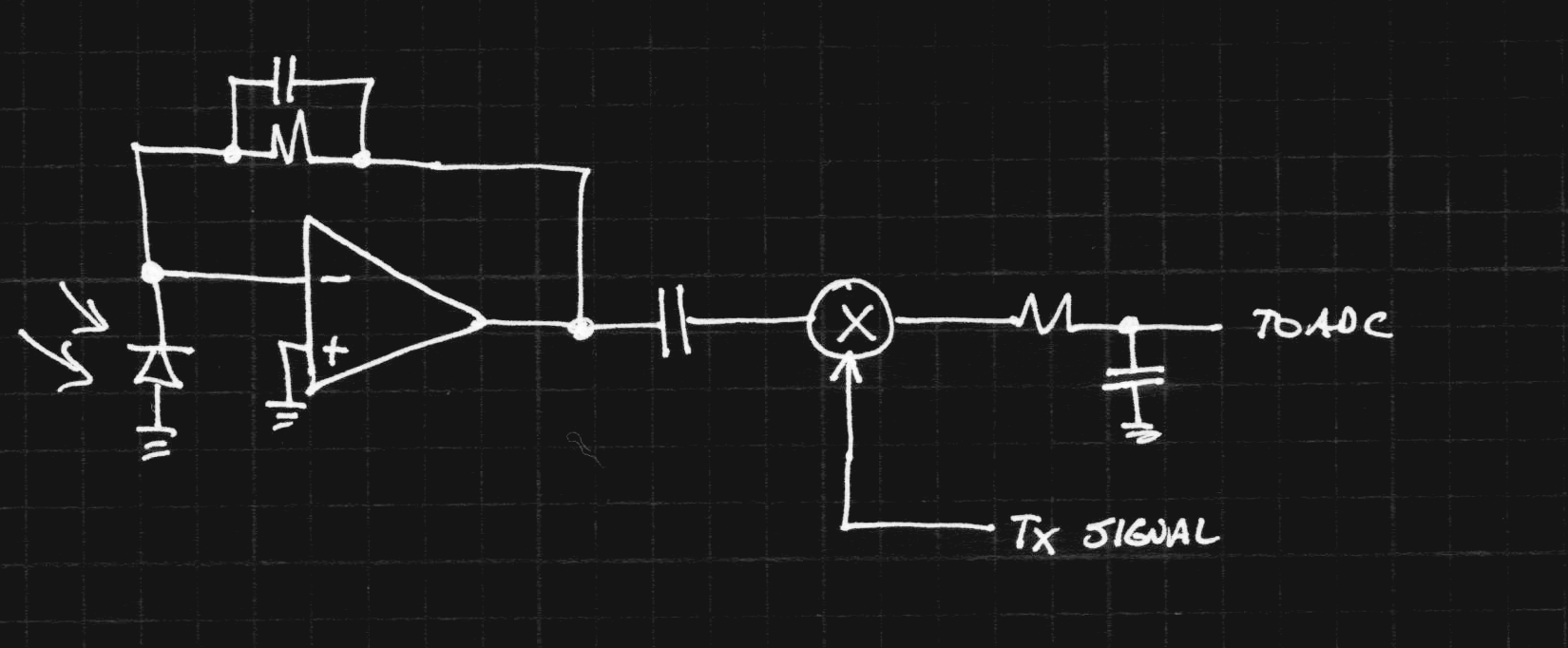
The photodiode is connected to an op-amp in transimpedance amplifier (TIA) mode - this converts an input current into an output voltage. I've done this before for light meters and such, and it works well, at least at DC. At higher frequencies, it becomes a bit more complex, although it's well explained in the literature. The output of the TIA is AC-coupled to a mixer, where it gets multiplied by the locally generated (transmit) signal. The original thought for this was a pair of CMOS switches, maybe 4066's (or something with lower resistance).
The upside to this approach is that the amplifier is still linear, unlike the Vishay learning-remote amplifier. The saturating behavior of that amplifier will degrade the mixing performance and limit the sensitivity of the receiver.
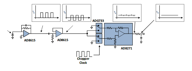
The mixing approach (synchronous detection) is used in lock-in amplifier designs to ignore background, as described in a technical report by Analog Devices. Their example shows CMOS switches in the mixing role:
The mixer idea seems sound, but there are several downsides to the transimpedance amplifier as a front-end. Speed may be an issue, but that can be solved by using a high GBW-product amplifier. The TIA can also experience gain peaking, which causes ringing on the output, but that can be tamed with a feedback capacitor as shown. These issues are described in the Hamamatsu photonics handbook.
The biggest problem with receivers like this is the wide dynamic range of the input signal, which can range over many orders of magnitude. The DC level (ambient light) in the environment many be much greater than the signal. In Photonics Rules of Thumb, they liken this to watching grass grow on top of the Empire State Building.
The Hamamatsu handbook has a partial solution: the use of a non-linear feedback element instead of a resistor in the TIA:
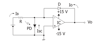
Due to the diode in the feedback path, the circuit yields a logarithmic response over several decades or more. Of course, the output varies wildly with temperature, so this simple circuit doesn't produce a very accurate log conversion without some kind of temperature compensation. But for purposes of ignoring the Empire State Building, accurate logarithmic output doesn't matter. The downside of this conversion is that AC signals are also log-transformed. A 1 nA AC signal on a 1 mA DC pedestal is going to look vanishingly small on a log scale (log(1e-3) ~ log(1.000001e-3)).
Another clue comes from a presentation from National Semiconductor, which shows a second amplifier being used as a DC servo to zero out DC bias errors:
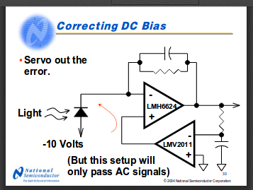
This is a way to remove DC signals from the input, but it still suffers from limited dynamic range, due to the resistor in the feedback path.
I have wondered for a while if you could combine these two ideas - a logarithmic DC servo. So, I fired up LTspice XVII and gave it a try tonight. Here's what I came up with after a little experimentation (these particular op-amps are just placeholders until I figure out what I really need):
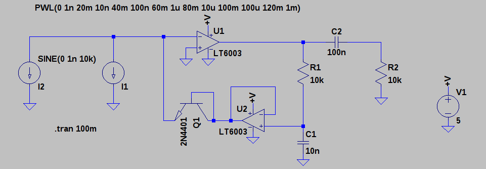
I1 and I2 represent the photo current through the detector, I2 is a sine wave of 1 nA amplitude, and I1 is the DC component (from lighting in the room). The DC value varies from 1 nA to 1 mA over the simulation run, 5 orders of magnitude). U1 is in a transimpedance amplifier role, with U2 servoing out the DC component, except with the inclusion of diode-connected transistor Q1 in the feedback loop. Transistors like this seem to obey a logarithmic response over a wider range than common diodes. The simulation looks like this:
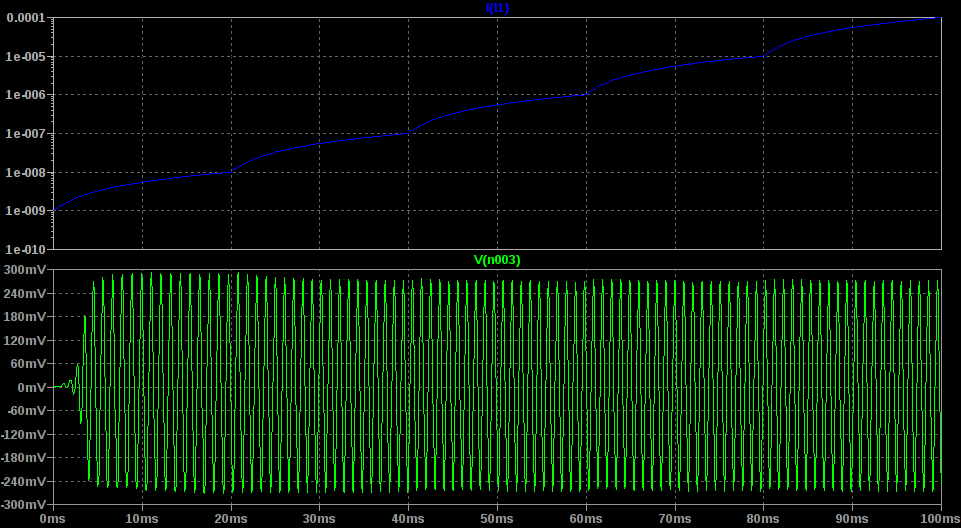
The top plot is the simulated DC photodiode current, while the bottom shows the detected signal output. The output result is essentially unaffected by the huge range of DC offset. So far it looks pretty good. (There must be something horribly wrong!)
EDIT:
I found out what was horribly wrong: the output is actually the circuit oscillating, not the detected signal. It gave me a good laugh - at least for a minute. Now it sucks. Time to try again. I knew it was too easy.
There are a few things to think about and work on. First, the two current sources are a poor model of a true photodiode. Good models exist, and it would be helpful to try this circuit with a more accurate model. I may consult the datasheets and have a look.
I don't know how to evaluate the stability of a system like this with a nonlinear element in the feedback loop. I may have to be satisfied if it just "works" on the bench.
Depending on the sources of interference that might be encountered, it might be useful to tune the RC filter in the servo loop. Many modern lights emit almost zero IR (LEDs, CCFLs), so even though they have fast switching edges, they may not produce significant interference. Again, some measurements are in order.
Finally, a more subtle issue is that of amplifier saturation with no input. This paper from TI explains the issue: with no input, the op-amp will saturate at the ground rail. In the saturated state, the amplifier may take a long (relatively) time to respond to an input signal. Their solution is to bias the virtual ground above the negative rail:
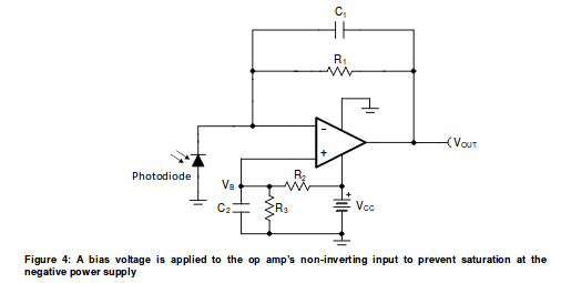
I will have to try integrating this into the front-end circuit.
So far, this approach looks promising. But I've been burned by SPICE simulation before: there's no substitute for actually building the thing.
Discussions
Become a Hackaday.io Member
Create an account to leave a comment. Already have an account? Log In.
I haven't really looked at op amp setups before, other than being aware of the basic inverting setup. I started looking last night (before you posted this). Fascinating things.
I had a couple of thoughts - firstly, are you using an APD, as this seems to suit eg laser range finders? Secondly, is there any way to modify an existing cheap laser range finder to exploit their optoelectronic parts and perhaps signal generator, such as the one I tried to reverse engineer (see my projects - it appears someone has cracked on of these more recent models and has put a link in the comments which I need to update the project details with). Lastly, can a summing amplifier be used to reject sensor and first stage op amp noise?
Are you sure? yes | no
Thanks for the comment, Simon!
It made me realize I hadn't yet discussed a few assumptions I'd already implicitly made. I'll put together a log or two about IR proximity/distance senor technologies and different sorts of detectors.
Quick answer: I've really only been considering Si PIN photodiodes, because they're cheap. APDs are very fast and sensitive, but also costly, and I don't really need that speed for what I'm doing. More exotic devices have the same problem.
But in general, looking for a device to hack is a good idea!
As for the laser range finder, there appear to be two types available. Big, expensive, and maybe hackable or tiny, cheap, and too integrated to mess with. Neither one seems like an easy win.
I'm not sure what you exactly mean about a summing amplifier reducing noise. Do you mean running a bunch of devices in parallel to reduce noise? That works (see the input stage of some audiophile amplifiers), but I don't think that kind of noise the the real problem in this case.
Are you sure? yes | no