 kodera2t
Before I made a PCB of 4bit TTL based CPU in another project,
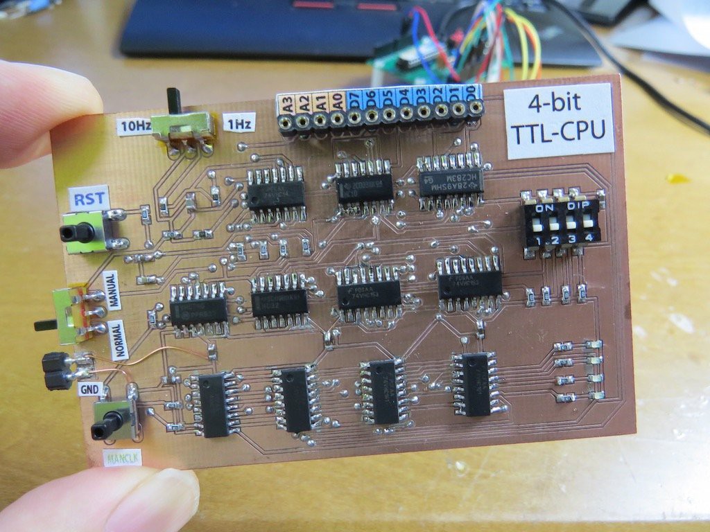
and this time I implemented it in CPLD. Actually this is a bit surprise for me to know that
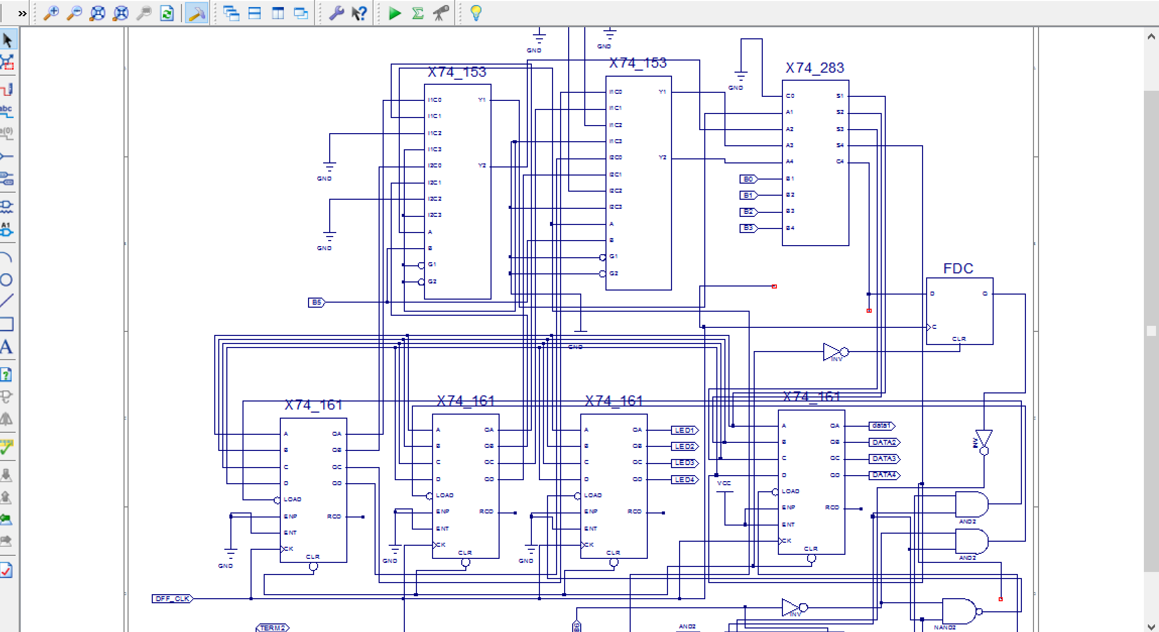
This CPU is made by "pure schematic drawing without HDL writing" !! ISE has lots of pre-defined 74 series components and just select it and connect wire will provide the circuit what you want!
I know, this schematic writing is NOT main stream of CPLD/FPGA implementation but if some student who is learning basic logic circuit, and hit on great idea, just writing schematic is very handy way to realise circuit!! I guess schematic implementation still has lots of potential for education purpose. I am not sure someone will try to make same 4-bit CPU, but already related sources are uploaded to github. And also XC95144XL board (with 3.3V regulator, FT231XS) schematic are also uploaded to github.
As same as "real TTL implementation", CPU operation is confirmed with ROM, which is emulated by Arduino. You may think LED blinking is just blinking, but
prog[0b0000]=0b10110001; //OUT(1011) "0001" to LED
prog[0b0001]=0b10110010; //OUT(1011) "0010" to LED
prog[0b0010]=0b10110100; // same till 0b1110
prog[0b0011]=0b10111000;
prog[0b0100]=0b10111001;
prog[0b0101]=0b10111010;
prog[0b0110]=0b10111100;
prog[0b0111]=0b10111101;
prog[0b1000]=0b10111110;
prog[0b1001]=0b10111111;
prog[0b1010]=0b10110000;
prog[0b1011]=0b10111111;
prog[0b1100]=0b10110000;
prog[0b1101]=0b10111111;
prog[0b1110]=0b10110000;
prog[0b1111]=0b11110000; // JMP(1111) to "0000" first of program
this code is running on CPU in CPLD! Have fun!
Discussions
Become a Hackaday.io Member
Create an account to leave a comment. Already have an account? Log In.
Awesome !
Are you sure? yes | no