Close
0%
0%

Standing waves of sound

An ultrasonic interferometer is assembled from optical drive components, 3d-printed parts and an ultrasonic range-finder.

Similar projects worth following
The Fabry-Perot interferometer finds application as a super high resolution optical spectrometer. Its ultrasonic cousin is rarely seen but provides access to the same wave-physics - the formation of standing waves between two slightly transparent mirrors. Here I describe a project to make a Fabry-Perot using sound waves. I'll go into the details of the low-cost build and analyse the data, by analogy to the optical case.

Standing waves occur when two waves (e.g. sound, light, water) of the same wavelength move through each other in opposite directions. This results in a characteristic pattern of nodes and anti-nodes, corresponding to zero and maximum wave amplitude. In an unconstrained system, standing waves could be observed at any wavelength. But usually systems are constrained in space, for example the guitar string is forced to have a node of zero vibration amplitude at either end, where the string runs out. In this case this leads to standing waves of only certain wavelengths, the ones that have a node at each end, giving the musical result that we all like.

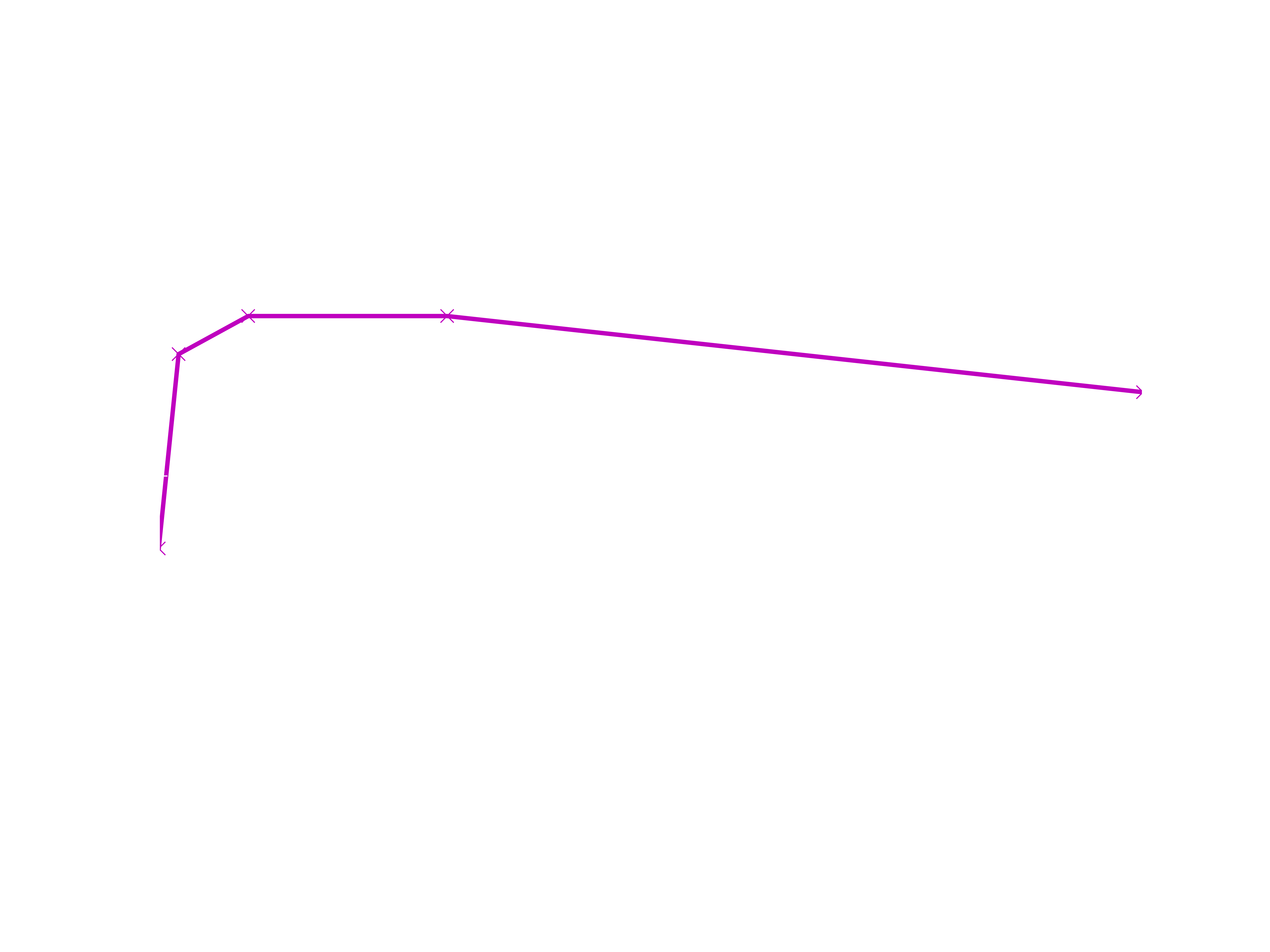
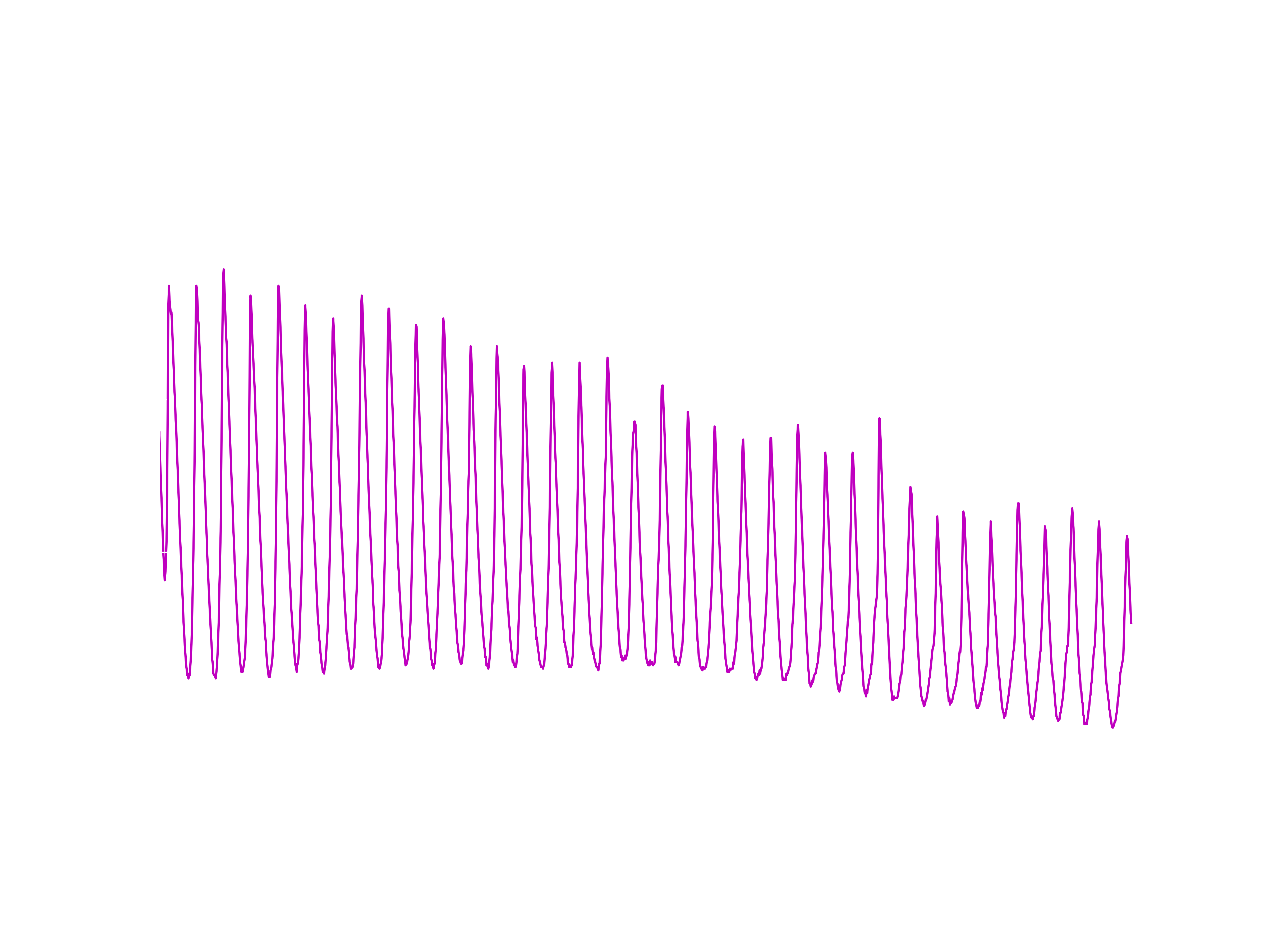
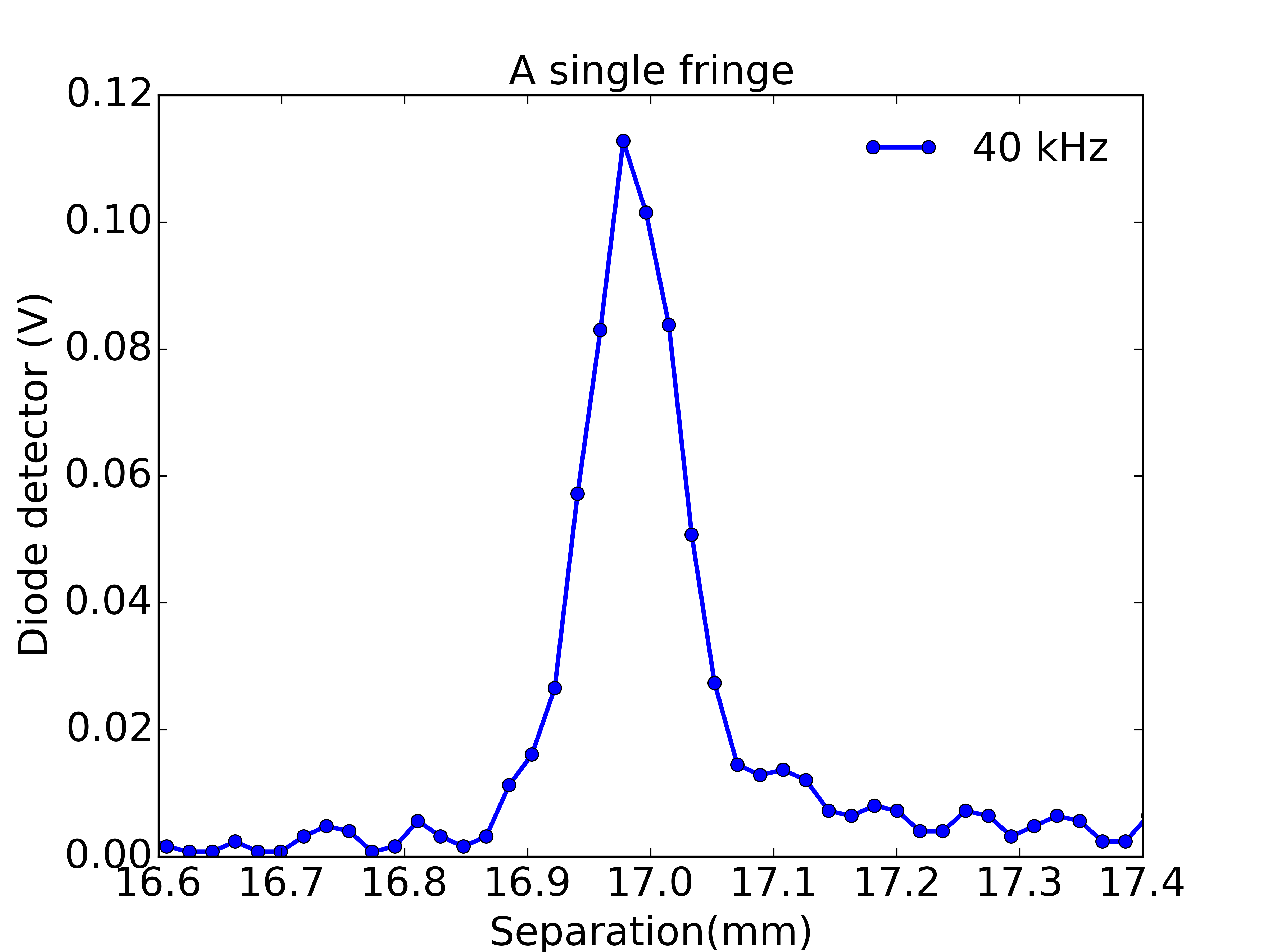
A useful case of standing waves occurs in optics with the Fabry-Perot spectrometer. This consists of two partially transmitting mirrors with their reflecting faces parallel and held apart by some separation. A standing wave pattern is permitted if the separation is an integer multiple of half wavelengths. In this case the system is constrained to have zero amplitude of electromagnetic field at the mirrors, which are just like the ends of the guitar string. It turns out that when this standing wave condition is satisfied then there is a maximum in transmission through the mirrors. The separation of the mirrors can be varied, and extremely sharp peaks in transmission are found around the standing wave conditions. The sharpness of these peaks allows this device to act as a spectrometer, as the distance between mirrors is scanned it becomes a controllable bandpass filter for light.

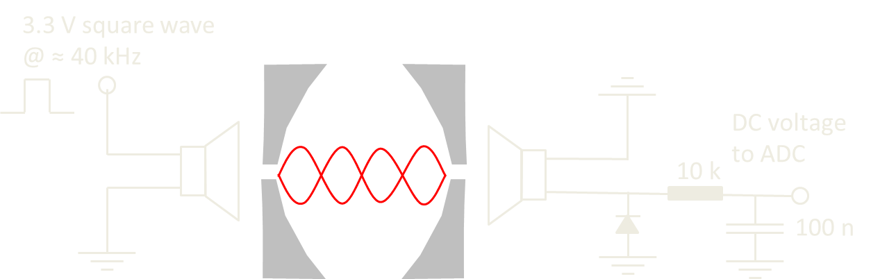
I thought it would be fun to play with a Fabry-Perot but they are a little tricky to setup at home so I decided to replicate the experiment with sound waves. In itself this is not going to provide a useful scientific instrument but it does provide an exact analogy to the optical case and lets us learn the physics behind this precision spectroscopy technique.

  • 1 × Teensy 3.1 or Arduino UNO
  • 1 × Germanium diode Demodulates the output from the ultrasound receiver.
  • 1 × Misc resistors and caps
  • 1 × EasyDriver board Drives the stepper motor.
  • 1 × HC-SR04 ultrasound range finder This commonly found unit was desoldered to provide a pair of ultrasound transducers.

View all 9 components

  • Motivation for an IQ detector in the ultrasonic Fabry-Perot

    Andrew Ferguson09/28/2016 at 20:07 0 comments

    Reading Ronald Quan's nice book 'Build your own transistor radios' inspired me to improve the detection circuitry on the ultrasonic Fabry-Perot (UFP). My first experiments had diode-detected the amplitude of the transmitted ultrasound signal through the semi-transparent mirrors. This approach is fine, though I was worried about the linearity of the diode, and it relates well to the optical case where intensity of transmitted light is usually detected.

    However, a defining characteristic of any type of wave is phase and if we purely measure amplitude or intensity we ignore this important information. We can do better by using a frequency mixer to determine both the amplitude and phase, or equivalently the in-phase and quadrature components of the transmitted wave. To see that these measures are equivalent, recall that a sinusoid with a phase shift can be decomposed into a sin and cos with specific amplitudes.

    Below are schematic drawings of the two detection approaches and over the next couple of posts I will show how an IQ measurement is implemented in the UFP by using the Tayloe detector, a commonly used detector in software defined radios.

  • Ultrasound amplifier PCBs

    Andrew Ferguson04/02/2016 at 20:22 0 comments

    After breadboarding the amplifier for the ultrasound signal and seeing that it worked fine I decided to get some PCBs made from OSH Park. Here's a picture of the soldered up PCB which still consists of a single transistor common emitter amplifier. The reason it is a 1 inch diameter circle is that it will be directly soldered onto the ultrasound transducer and look prettier that way. There are some unsoldered parts here because I want to play with making it a tuned amplifier, by having a parallel resonant circuit as the collector load, but I didn't test this yet. The input pins are in the middle and the output and power pins to the left. The transistor is a BC847 in a SOT23 package, chosen since it is a general purpose npn bipolar. The resistors and capacitors are in 0805 packages.

    The circuit diagram is as follows, I changed the degenerated emitter to include a resistor (R_E2) in series with the bypass capacitor (C_E) as I hoped this would give me more predictable gain.

    The measured gain is as follows, for an input amplitude of 10 mV. Gain compression starts to occur at an input amplitude of 50 mV, much more than I am expecting from the ultrasound receiver. I'm still pretty happy with this design which is now giving a voltage gain of 28 at 200 kHz (the transducer frequency) and next will play with tuning the collector load to reduce out-of-band noise.

  • Latest interference fringes

    Andrew Ferguson02/23/2016 at 19:56 0 comments

    I just wanted to show some interference fringes using both the following:

    1: The Si5351 as the oscillator - driving the ultrasound transmitter.

    2: The single transistor amplifier (described in the previous log entry) amplifying the receiver signal, before envelope detection.

    I think it is pretty awesome that these are interference fringes of sound and we are seeing up to about the 54th maxima.

  • An amplifier for the ultrasound receiver

    Andrew Ferguson02/20/2016 at 21:42 0 comments

    I am looking to boost the 200 kHz signal from the ultrasound receiver from 10's of mV towards 1 V, so that when it is demodulated I fill the UNO's ADC range (presently set to 1.1 V) with as much signal as possible.

    At work, I use several different types of amplifier and, via the usual arguments, it doesn't make sense for me to build them. At home, the solution to the buy or build equation is biased differently, so I get to make my first amp...

    For simplicity, the design will be an AC coupled, single stage common emitter amplifier using a NPN transistor.

    First considering the caps, I have some 100 nF polys at home and their reactance at 200 kHz is 8 Ohms, so these should work OK at the input and output.

    A reasonable V_B seems to be about 1.2 V, so this gets set with a voltage divider consisting of a 1k Ohm and 330 Ohm resistor. Unfortunately I didn't measure the impedance of the transducer yet, but I think it will be somewhere between 100 and 1000 Ohms, so the resistor values seem sensible.

    Guessing the base-emitter voltage drop to be 0.6 V, we then have a V_E of 0.6 V. For no particularly good reason, except that I don't want the output impedance to be too high, I chose R_E = 100 Ohms. This means that I_E is about 6 mA, allowing us to choose R_C = 470 Ohms, so that V_C is close to 2.5 V.

    The emitter resistor is going to be bypassed with a 100 nF cap to give us a sensible voltage gain of about g=470/8= 59 at 200 kHz. The final circuit looks as follows and let's see if it works as expected.

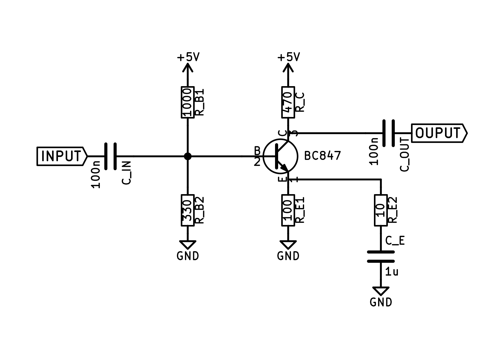
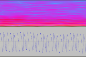
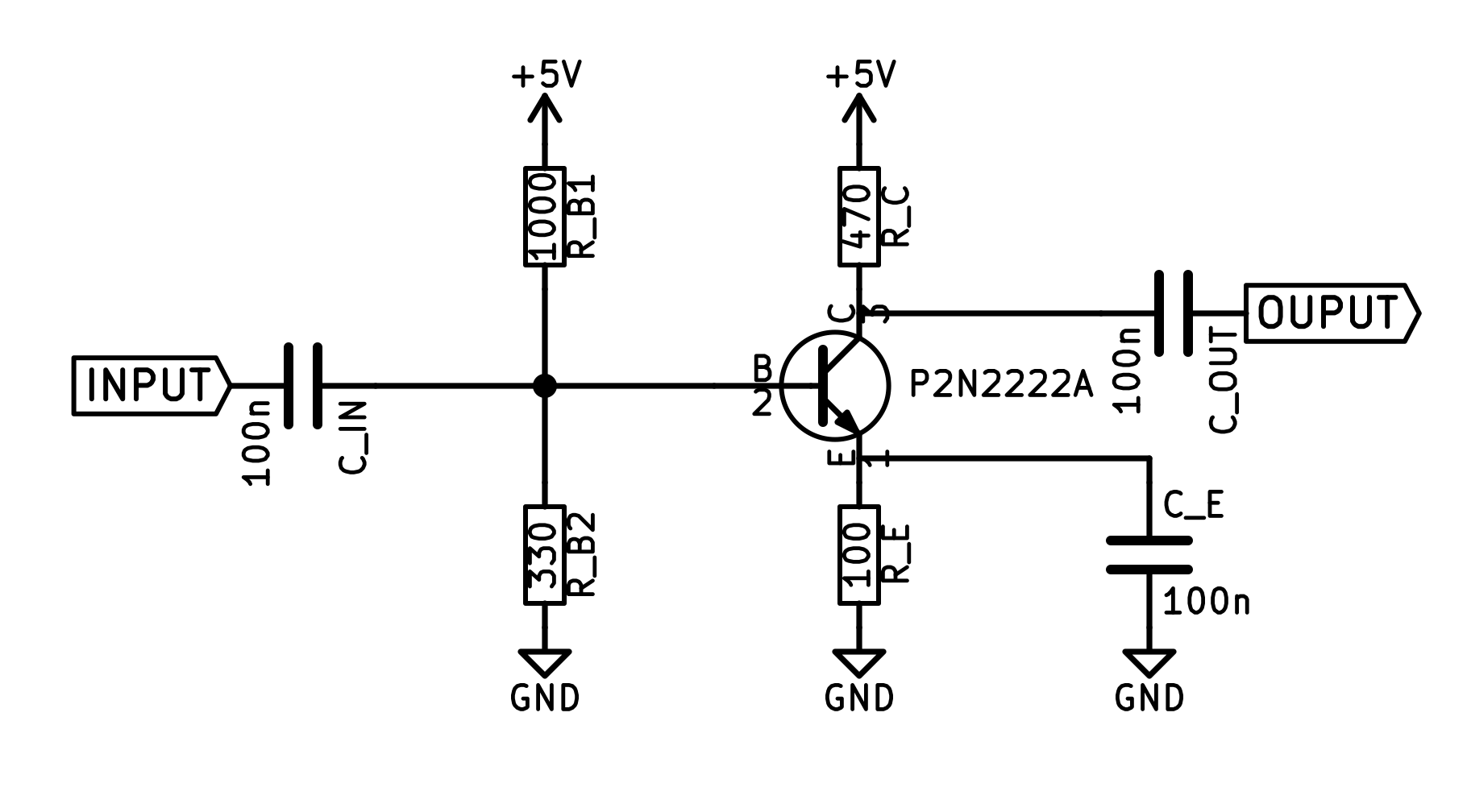
    So, here is a time trace of the input to the amp (from the ultrasound transducer) as well as the amp's output. It has gain! In fact, the voltage gain is 47, so the simple calculations turned out to be not too bad. And, the output signal is of about the right amplitude. I am delighted, this amp is just what is needed.

    My to do list:

    1: Move this circuit off the breadboard.

    2: Put a parallel resonant circuit as the collector load, so as to make this a tuned amplifier, rejecting out of band signal.

    3: Measure the impedance of ultrasound transducer and tune input impedance of amplifier to match this.

  • Checking out the transducers - impulse response

    Andrew Ferguson01/30/2016 at 22:15 0 comments

    I wanted to have a look at the frequency dependence of the ultrasound transducers, separately from the ultrasonic Fabry-Perot (UFP). Here, I subject the transducer to a single 2 us pulse generated by Timer 1 on the UNO and look at the time domain response with a Rigol scope. Immediately after applying the pulse it is essential to send the drive pin to a high-impedance state with pinMode(X,INPUT), otherwise the transducer response is damped out almost immediately.

    The Fourier transform is probably more useful and shows at least a pair of modes at around 200 kHz, where the transducer is specified for operation as a transceiver. There is also a much more significant mode at about 270 kHz, which will be worth looking at with the UFP.

    It will be interesting to discuss this behaviour in terms of the equivalent circuit of the transducers but I will have to leave that for another time.

  • A new oscillator in the interferometer - the Si5351

    Andrew Ferguson01/28/2016 at 21:02 2 comments

    Previously I was using a timer generated square wave (f=200 kHz, Vpp=10 V) to drive the ultrasound transmitter. However, noise (perhaps timing jitter) in this oscillator was broadening the interference fringes, so I was looking for a better drive. In my first attempt to replace the oscillator I picked up a Si5351 chip on a breakout board from Adafruit. This chip outputs up to 3 square waves with Vpp=3.3 V, at frequencies between 2.5 kHz and 200 MHz. Here is the first data which look promising but, as you can see, I now need an amplifier on either the source or the detector side, since the reduced drive amplitude is only giving a 10 mV signal at the detector.

  • Oscillator noise

    Andrew Ferguson01/16/2016 at 23:12 0 comments

    I'd been noticing an asymmetric lineshape on the interference maxima at 40 kHz and it became particularly obvious at 200 kHz. I suspected two possible causes, either vibration on the moving state modulating the path length or phase noise/jitter on the ultrasound transmitter drive. I used a old but good quality HP function generator from my work lab to help me pin-point the cause.

    The graph shows a zoom-in for scans at 200 kHz with different sources driving the transmitter. I used the HP source to drive with either a sinusoid or a square wave. And I used the timer generated square wave on the UNO for comparison. I was surprised to find such a big difference between the UNO and HP data. The HP data is clearly much more as one would expect for a Fabry-Perot, showing that the spectral purity of the UNO timer generated signal (at least as it is used now) is not good enough for this application.

    I was even more suprised to find a difference between the HP sinusoid and square-wave drive, with the sinusoid yielding higher Finesse. I expected that the Fourier components of the square wave would be too high in frequency to affect the narrowband transducer but perhaps this was wrong.

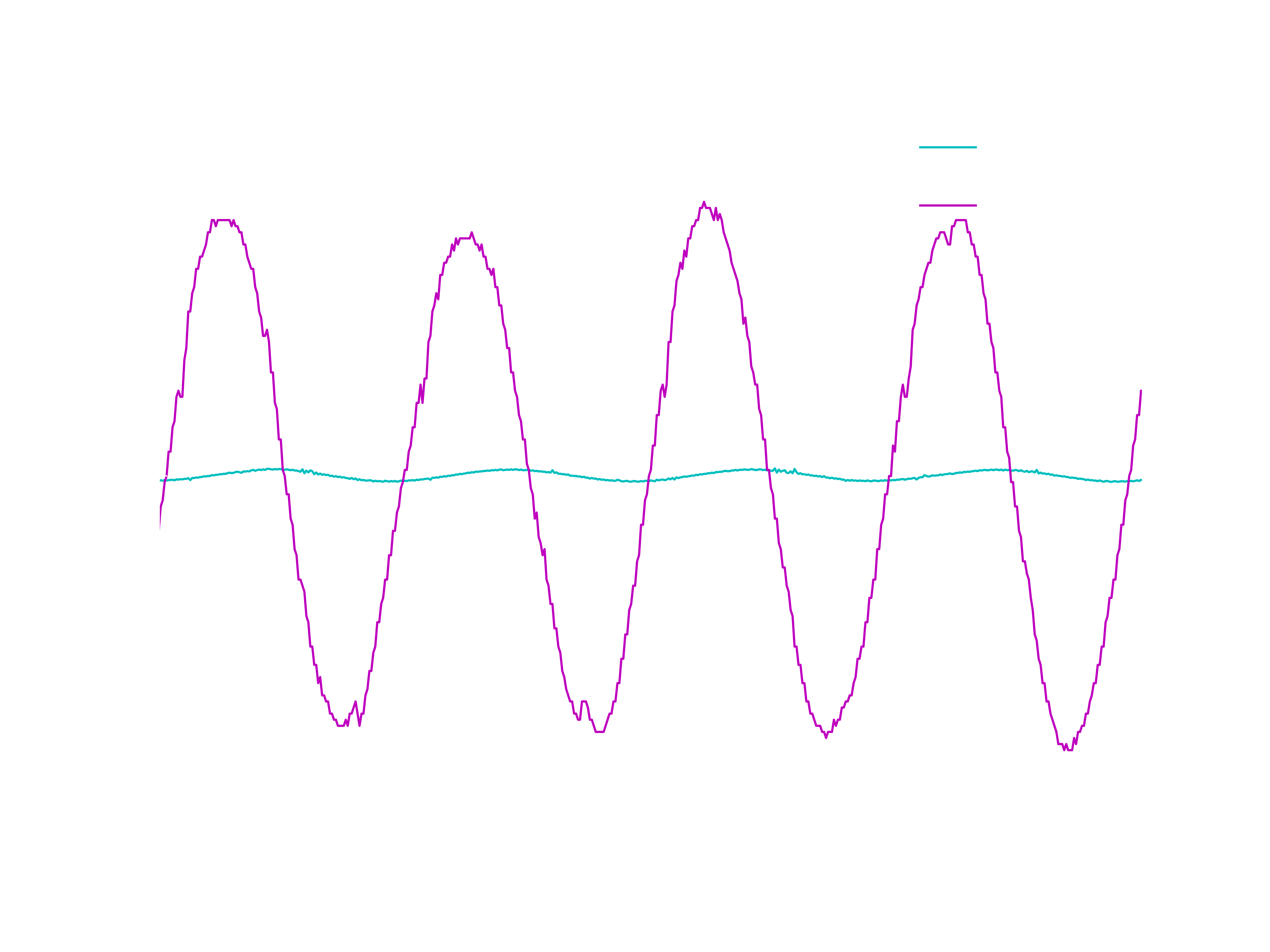
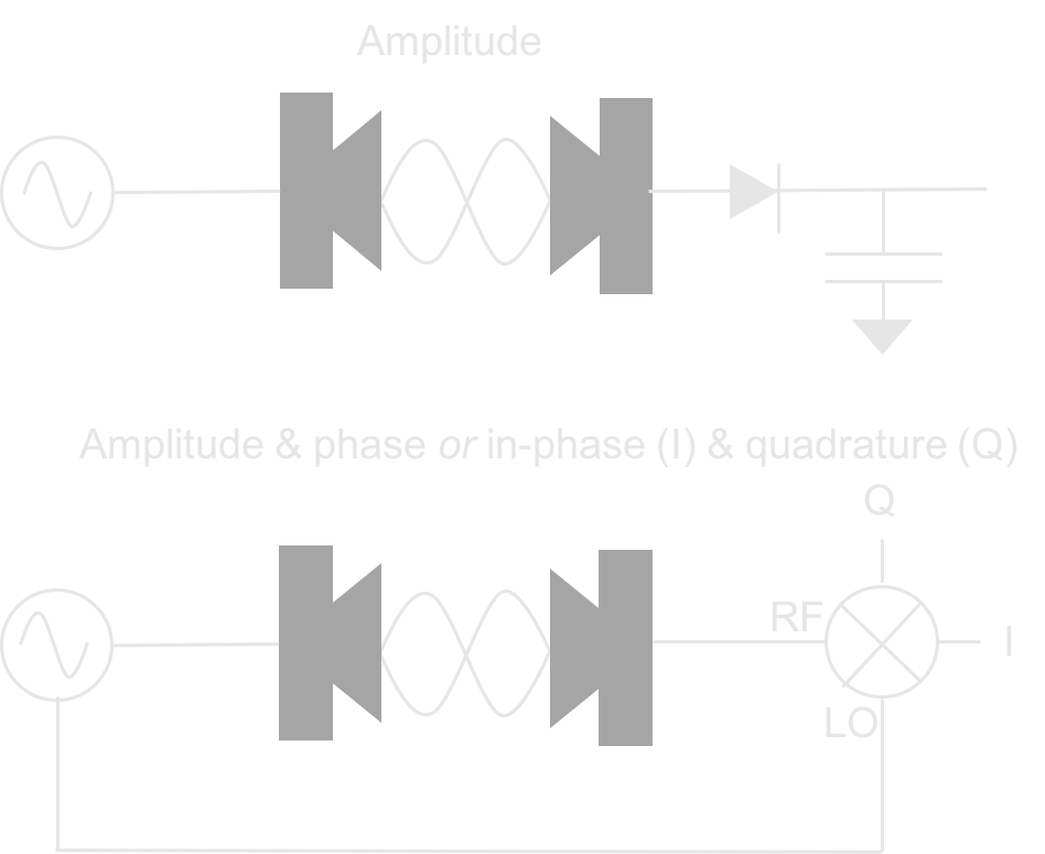
    So this gives me a challenge, to implement a digitally tunable sinusoidal drive in a compact and cheap way. One of the many options would be to use an AD9850 DDS chip. Or perhaps I can use a Si5351 clock generator and low pass filter the output. Needs some thought but it will clearly be worthwhile to use a better oscillator.

  • Up in frequency

    Andrew Ferguson01/14/2016 at 21:51 0 comments

    I was keen to see more fringes, mainly because it will help with future measurements e.g. of the speed of sound. Optical Fabry-Perots may operate at about the 100,000 order, and therein lies their strength as spectroscopy tools, but with 40 kHz ultrasound I was stuck at about the 5th order! So I took the plunge and bought some transducers that would push up my ultrasound frequency. I found some 200 kHz transceiver units at reasonable cost and installed them in the setup, starting with planar mirrors.

    Here is one of the first datasets, showing more than 30 fringes over the travel range:

    For a number of reasons the signal has gone dropped to 10's of mV, so one of my next steps will be to build a small amplifier for the receiver. Otherwise, I am pretty happy with the upgrade. Once I have more signal, it will be possible to push the Finesse up, if desired.

  • Mechanical improvements

    Andrew Ferguson01/04/2016 at 21:35 2 comments

    I wanted to improve on first build of the interferometer, the reason being that the stage lacked mechanical integrity. It slightly wobbled and showed stick-slip behaviour when driven. The main reason for this, as you can see in the photo of the first build (below), was that I only used two ball-bushings, and this allowed the stage to rock and yaw. A secondary reason was that the leadscrew drive was off the stage axis, meaning that a different couple was applied to each bushing during motion. The off-axis drive can be fine, as long as the bushings fit the rails perfectly (it is used in the optical drive) but I was worried about it.

    So in the second build (shown below) I have used four bushings on a larger stage and moved the leadscrew to the axis of the stage. The stage now shows vastly less wobble and there is no obvious stick-slip behaviour. In the future I'd like to quantify the stage's performance in terms of precision and repeatability. But for now I am happy to note there are no unwanted jumps in the data, as occurred previously.

    Here is a zoom in of the stage itself.

  • Differential drive for the ultrasound transmitter

    Andrew Ferguson01/02/2016 at 20:35 0 comments

    I had been driving the ultrasound transmitter in a single-sided way, using the tone() function to output a square-wave to one side of the transducer while keeping the other side grounded. Using the Uno, this gives a 2.5 V amplitude square-wave drive to the transmitter. However a single-sided drive doesn't make the most of the microcontroller and instead of grounding the other side of the transmitter we can drive it with the complement of the other pin. This yields a 5 V amplitude square-wave, winning signal on the detector side.

    I spotted the toneAC library after I had written code to implement these waveforms using timer1. It should do the trick nicely.

    It seems to have worked, the graph below shows the change in signal size at the detector between single-sided and differential drive. I was expecting exactly a factor of two gain in signal size, but there is a little more than this and I will have to figure out why. You never quite get what you expect! Anyway, this is all good and I will be using differential drive from now on.

View all 11 project logs

  • 1
    Step 1

    The analog circuitry

    One of the digital pins of the microcontroller is programmed with a square wave using the tone() function, this drives the ultrasound transmitter. It is a lower voltage than usual for driving a piezoelectric transducer but enough in this case, since we are not range-finding and looking for low amplitude echoes.

    On the receiver side, it is possible to directly digitize the ultrasound signal using the Teensy 3.1, making use of the fast ADC library from Pedvide. Then the amplitude can be determined from fitting the signal or taking a FFT. However, it is much easier to rectify the voltage using a germanium diode and low pass filter the output with a RC filter. Then the ADC can directly read out the amplitude of the signal.

  • 2
    Step 2

    The stepper motor and stepper motor drive

    I am using the stepper motor that originally translated the sled in the optical drive. See the project by esot.eric for a nice resource on repurposing optical drives. Our drive has 20 full steps per revolution. It is being driven by the EasyDriver which defaults to 8 microsteps, giving 160 microsteps per revolution. The EasyDriver is set to its minimum current of about 150 mA.

    The helical pitch of the leadscrew attached to the motor is close to (and perhaps exactly) 3 mm, giving 18.5 microns displacement per microstep. By the way, does anyone know how many microsteps are used with similar steppers in a real optical drive?

    It turns out that this is a pretty useful resolution for the spectrometer, though I would be happy for a bit more... In the figure below, the ADC is being read each microstep over a single interference maxima. You can see about 10 data points per fringe.

View all instructions

Enjoy this project?

Share

Discussions

Beaglebreath wrote 12/17/2015 at 20:04 point

I'm sure you've read through Sam's FAQ pages regarding his DIY Fabry-Perot interferometer.  And thank you for describing the concept in terms of the guitar string.  I thought I knew how these work, but the analogy helped it gel up in my mind.

  Are you sure? yes | no

Andrew Ferguson wrote 12/17/2015 at 23:18 point

Thanks for the tip. I didn't see the part in Sam's FAQ pages about his Fabry-Perot builds. They are awesome. 

  Are you sure? yes | no

arief ibrahim adha wrote 12/17/2015 at 08:57 point

any picture for assembly process?

  Are you sure? yes | no

Andrew Ferguson wrote 12/17/2015 at 23:09 point

Yes, it is all coming, but will take me a few days to post. 

  Are you sure? yes | no

helge wrote 12/16/2015 at 22:54 point

superbly executed. I can see this being an excellent filter for acoustic OFDM data transmission.... or for low power anemometer where transmission is measured instead phase / frequency shift? I wonder...

  Are you sure? yes | no

Andrew Ferguson wrote 12/17/2015 at 23:14 point

Thank you. I am looking forward to having some fun with related experiments. I am thinking about using the instrument to measure amplitude modulated ultrasound signals but first want to finesse the build.

  Are you sure? yes | no

Similar Projects

Does this project spark your interest?

Become a member to follow this project and never miss any updates