 Andrew Ferguson
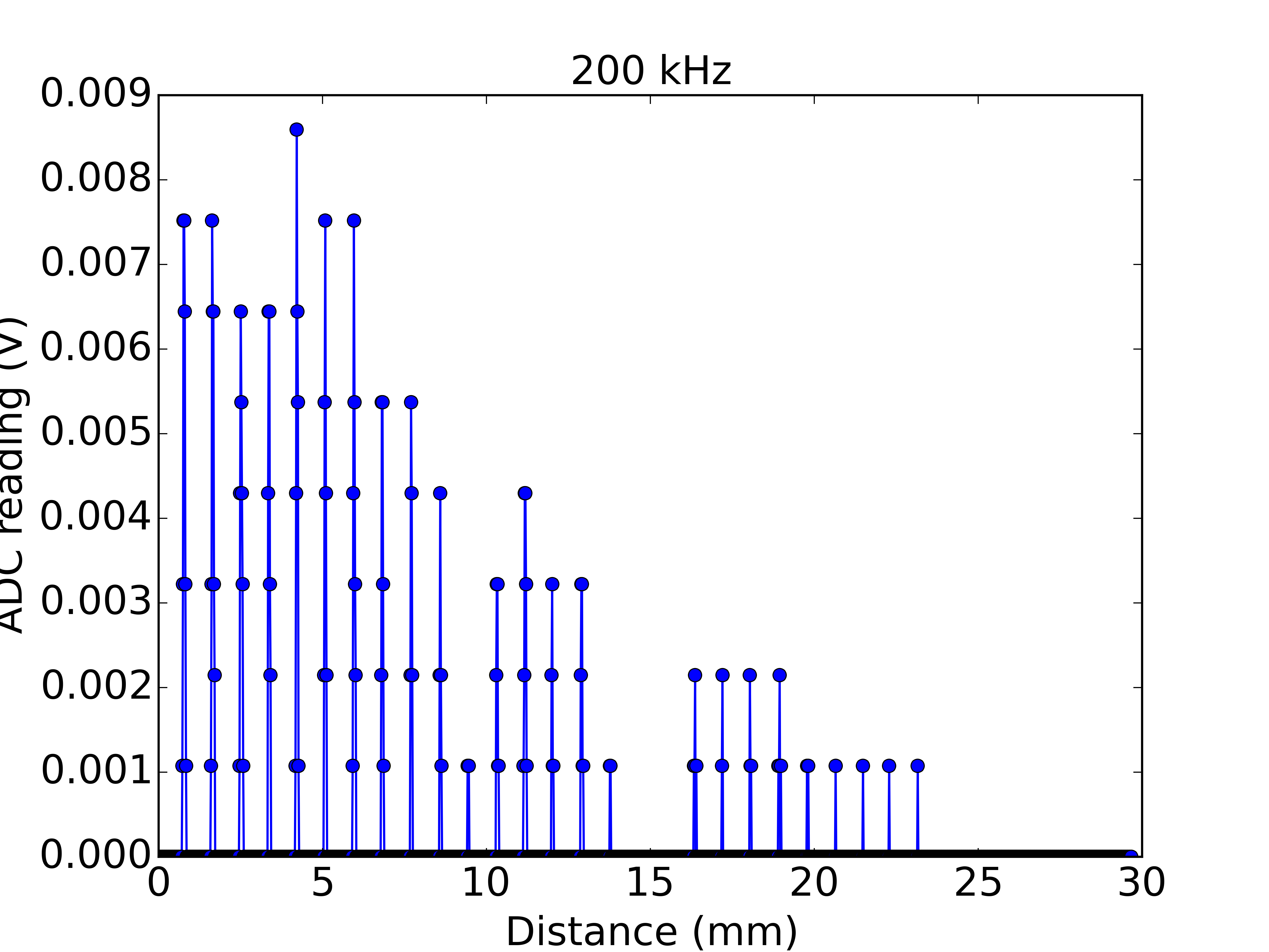
Previously I was using a timer generated square wave (f=200 kHz, Vpp=10 V) to drive the ultrasound transmitter. However, noise (perhaps timing jitter) in this oscillator was broadening the interference fringes, so I was looking for a better drive. In my first attempt to replace the oscillator I picked up a Si5351 chip on a breakout board from Adafruit. This chip outputs up to 3 square waves with Vpp=3.3 V, at frequencies between 2.5 kHz and 200 MHz. Here is the first data which look promising but, as you can see, I now need an amplifier on either the source or the detector side, since the reduced drive amplitude is only giving a 10 mV signal at the detector.
Discussions
Become a Hackaday.io Member
Create an account to leave a comment. Already have an account? Log In.
Thank you K.C. - this was a great comment.
I've not come across MOSFET gate drivers before but they look well suited to driving ultrasound transducers. I particularly like that there are a pair of complementary outputs. Time to see how the UCC37325 boosts the signal!
Cheerio, Andrew
Are you sure? yes | no
You might want to look into using a MOSFET gate driver. They are designed to drive high capacitive loads and can do the level shifting for 10V from a LVTTL input.
UCC37325 - 4A driver - one of them is inverting and the other one is non-inverting.
I was going to recommend the TPS2813, but found out that the input is CMOS threshold and not LVTTL like the UCC37325.
Are you sure? yes | no