 C. Prichard
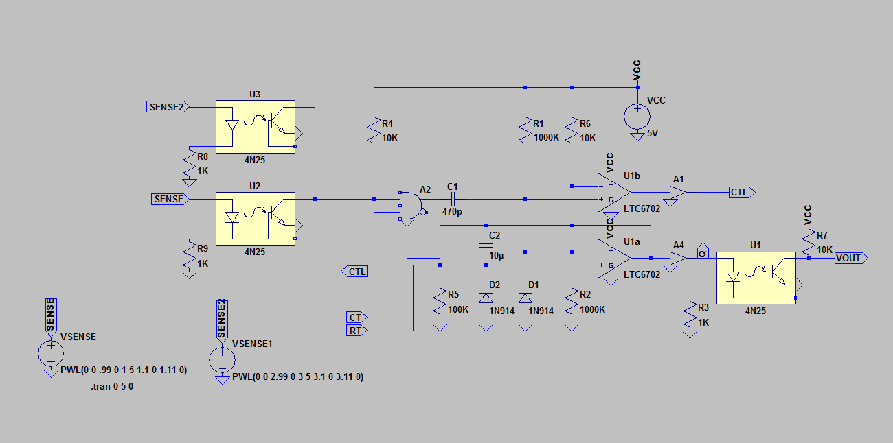
As sensors are a huge part of this idea, I am considering possible benefits from combining sensors with 1SHOT pulses. Isolation is easily accomplished, and sensors can be combined to generate a composite pulse. There are possible benefits in security where sensors are not continuously using power. A cheap processorl-less RF connected device/sensor might only come on after receiving a trigger via the RF receiver. Trigger for this circuit is a very short pulse of energy on the input. The output can be used to switch power to other circuitry such as thed RF transmitter. The approach can make security sensors more difficult to detect. It can save power, making it practical to use a small solar panel, and chargeable battery.
Output of this device is 1 or 0. If used to create a voltage into a combiner amplifier, the amplifier output containing other sensor information can be read as an analog input to Arduino. There might be some advantages to combining such a sensor with the 1SHOT device...
 /* Arduino Micro Code

Emulates back-to-back oneshot model with two delays. Example shows input sense, and output control.

*/

                                      // Global Constants
const int swPin = 10;                    // switch pin reference
const int led = 13;                      // LED reference
const int sync_Pout = 11;                // sync output pin reference

const int p0_Pout = 2;                   // references for P0-P3 output pins
const int p1_Pout = 3;
const int p2_Pout = 4;
const int p3_Pout = 5;

const int prq0_Pin = 6;                  // references for PRQ0-PRQ3 input pins
const int prq1_Pin = 7;
const int prq2_Pin = 8;
const int prq3_Pin = 9;
                                         // 600000 = 1 minute in milliseconds
const long delay_Sync = 100;             // 100 millisecond sync pulse

const long tsl_P0 = 10000;               // P0 timeslice (10 seconds, adjust for desired delay.)
const long tsl_P1 = 100;                 // P1 timeslice
const long tsl_P2 = 600;                 // P2 timeslice
const long tsl_P3 = 600;                 // P3 timeslice

                                         // Global Variables

int prq0_State = LOW;                    // loop PRQ_0 state
int prq1_State = LOW;                    // loop PRQ_1 state
int prq2_State = LOW;                    // loop PRQ_2 state
int prq3_State = LOW;                    // loop PRQ_3 state

unsigned long pTime = 0;                 // present time
unsigned long lTime = 0;                 // beginning loop time
long Timer = 0;                          // loop timer

// int swState = 0;                      // current switch state
long timeslice = 0;


void setup() {

  pinMode(led, OUTPUT);                  // set the LED pin as output
  pinMode(sync_Pout, OUTPUT);            // set the syncOut pin as output

  pinMode(p0_Pout, OUTPUT);              // set the prioritized output pins as outputs
  pinMode(p1_Pout, OUTPUT);
  pinMode(p2_Pout, OUTPUT);
  pinMode(p3_Pout, OUTPUT);

  // pinMode(swPin, INPUT);              // set the switch pin as input

  pinMode(prq0_Pin, INPUT);              // set the priority request pins as input
  pinMode(prq1_Pin, INPUT);
  pinMode(prq2_Pin, INPUT);
  pinMode(prq3_Pin, INPUT);

  digitalWrite(led, LOW);                // Initialize LED LOW
}

void loop() {
                                         // declare and assign loop variables
  int prqState = LOW;                    // Used to determine if demand is fulfilled.
  int pOut = LOW;                        // Used to set and clear output assertion.
  int prq_Pin = LOW;                     // Used to remember which input to test for state change.

  digitalWrite(sync_Pout, HIGH);         // generate a sync pulse
  Timer = 0;
  lTime = millis();
  do {                                   // This delay can be interrupted.
                                         // Read the PRQ inputs
  // prq0_State = HIGH;                  // prq0_State = digitalRead(prq0_Pin);
  prq0_State = digitalRead(prq0_Pin);    // TEST here verifies PRQ inputs are HIGH unless pulled LOW.
  prq1_State = LOW;                      // prq1_State = digitalRead(prq1_Pin);
  prq2_State = LOW;                      // prq2_State = digitalRead(prq2_Pin);
  prq3_State = LOW;                      // prq3_State = digitalRead(prq3_Pin);

    pTime = millis();                    // Is also useful for input sense
    Timer = pTime - lTime;
  }
  while (Timer < delay_Sync);
  digitalWrite(sync_Pout, LOW);

  if (prq0_State = HIGH) {               //Can program a switch to reverse priority...
    prq_Pin = prq0_Pin;
    timeslice = tsl_P0;
    pOut = p0_Pout;
  }
  else {
          if (prq1_State = HIGH) {
            prq_Pin = prq1_Pin;
            timeslice = tsl_P1;
            pOut = p1_Pout;
          }
          else {
                  if (prq2_State = HIGH) {
                    prq_Pin = prq2_Pin;
                    timeslice = tsl_P2;
 pOut = p2_Pout;
...
Read more »
 Lee Sampson
 Tauno Erik