 James Cannan
Muscle (EMG) Sensor
What is EMG?
This section is quite technical. If you don't want to know what EMG is in depth then skip ahead to the next section. All you really need to know is EMG measures very small electrical signals that occur when our muscles move, such moving a finger, clenching a fist, or lifting your arm up.
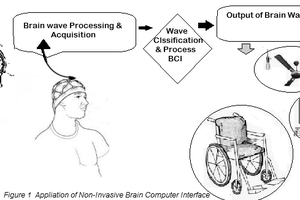
Electromyography (EMG), which roughly translates to ’electrical muscle recording’, can be used to control a variety of devices. It was originally a medical procedure to analyze muscles and nerve health, but as it grew in popularity it expanded into areas of biomechanics, sports, rehabilitation, and was first used in a commercial prosthetic limb back in the 1980’s. Nowadays it is also used as a human computer/robot/machine interface.
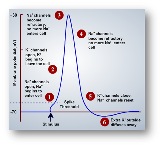
The bulk of the EMG signal can be detected in the 0-500hz frequency band; it is quite a complex signal, and to understand its formation it is important to appreciate where the signal comes from. As you can imagine, it all originates from the brain. The brain initiates the control sequence and passes nerve impulses through the nervous system, similar to the flow of electrical current through a metal wire, the nerves then excite or activate Motor Units(MU), which then control the contraction of the muscle fibres. For very fine low force movements small MU are used, as more force is required, more and larger motor units are recruited to activate the muscle fibres. A single MU produces an Action Potential(AP), which is shown in the image below. Each action potential occurs due to a chemical exchange in the body of potassium (K+) and sodium (Na+) ions.
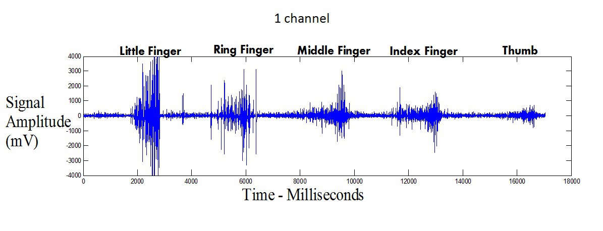
Muscles create many action potentials during a movement, like moving your arm or closing your hands. This creates a signal similar to the image below, which shows an increase in signal due to different fingers moving.
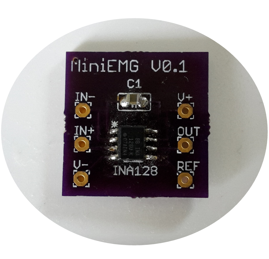
The Super Simple EMG Circuit
Early Prototype Without The Diode
--------------------------------------------------------------------------------------------------------------------------
SAFETY NOTICE
I highly recommend you only use batteries with this circuit. As connecting to mains power can be dangerous without proper isolation.
----------------------------------------------------------------------------------------------------------------------------
The super simple EMG muscle sensor described here will help make it easier for people play with EMG. It uses a ultra simple 3 piece EMG circuit, consisting of an INA128 Instrumentation Amplifier (IA), a capacitor, and a rectifying diode to perform half wave signal rectification (which basically removes all the negative voltage signal so you don't damage your analogue pin on your microcontoller).
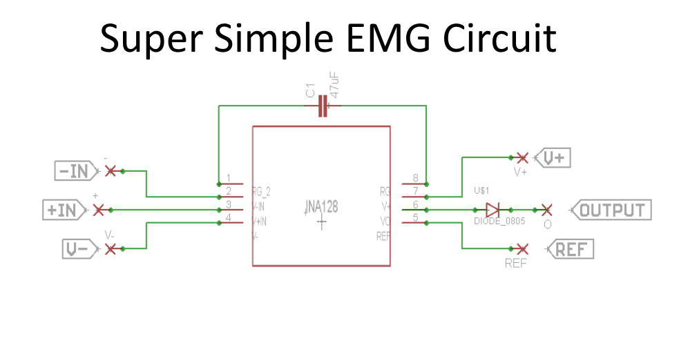
The instrumentation amplifier, amplifies differential inputs and subtracts the common mode signal (bascally takes two signals and subtracts what is common in both), which causes noise presented on both channels to be partially suppressed. The super simple EMG circuit uses a capacitors reactive impedance attached to the IA gain pins, which sets a variable frequency dependant gain, thereby only amplifying higher frequencies, and thus creating a similar affect to a high pass filter. The capacitors impedance (which is inversely proportional to the IA amplification) is calculated from below equation
Impedance = 1/(2 ∗ PI ∗ Frequncy ∗ Capactance)
The EMG sensor requires 3 electrodes, a negative, positive and ground, with the positive and negative placed adjacent to each other, and separated by a 1cm gap. These electrodes are placed over the muscle you want to monitor, and the ground electrode placed over a bony area with minimal to no muscle activation. The exact locations of the electrodes can be determined by trial and error. The electrodes used were 30mm diameter, reusable, self-adhesive, and long-term electrodes often found in TENS, EMG and Neuromuscular stimulation applications.
The only other additions you will need to see...
Read more »

 ensafatef
 Tom Goff

 Lithium ION
Safety requires that any circuit you hook to yourself be ground isolated.