 jeromekelty
The electronics for this suit aren't really that complex once it's broken down into separate systems. The reason I wanted to make the left side/right side and boots separate systems was so they could be run at the same time and if one system went down the rest of the suit would still operate.
The left side takes the RFID tag input from two fingers on the left hand and then the Arduino will operate either the helmet functions (via the XBee radio) or it will have the hip pods and back flaps run through a programmed sequence.
The right side takes the RFID tag input from two fingers on the right hand and then a second Arduino operates either the hip pods or shoulder rockets, depending on which tag is read. If the hip pods are selected then the WaveShield is also triggered to play a sound effect.
The IR sensor in the right boot sends a signal to another Arduino that operates the lights for the boots and triggers the WaveShield to play a sound effect.
For testing purposes I glued RFID tags and a tag reader to a glove to get an idea as to how easy it would be to operate, since the tag reader can only read one tag at a time. Reading two tags at the same time gives zero output. I was worried that since the fingers were in close proximity to one another this could be a problem, but it turns out it worked just fine.
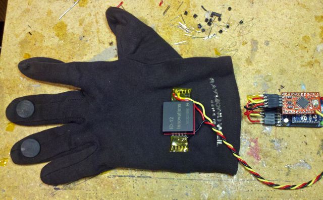
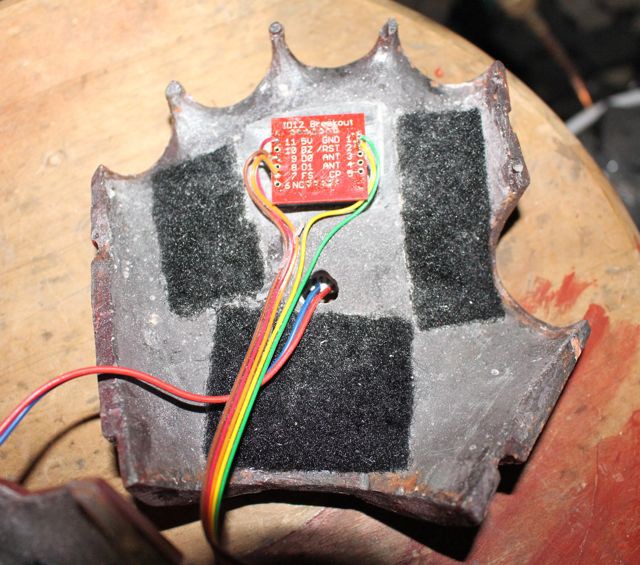
The tag reader was then mounted to the inside of the fiberglass suit glove shell using adhesive foam tape. The back side of the board was then taped over to protect it and the lead wires. The glove clam shells fit over a batting glove so the wearer's hand never comes in contact with the board.
The gloves have extension leads that connect to the gauntlets, which have Ethernet jacks for connecting to the Ethernet cables that run through the arms. The left gauntlet is pretty much empty while the right gauntlet has AA battery holders as well as a small connector board for the servo wires.
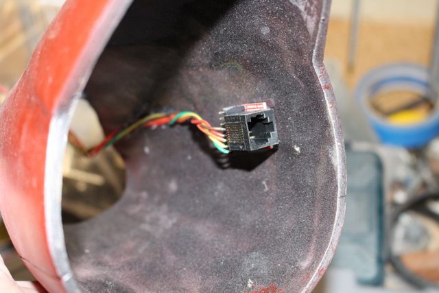
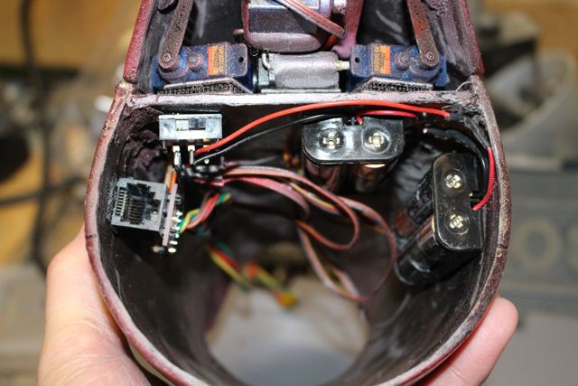
The servo wires are run through a hole in the gauntlet base plate.
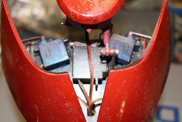
The three Arduino ProMinis are mounted in the back of the upper torso section along with batteries and power switches for each system. The WaveShield sits atop the Arduino Pro in the center. The transmitting XBee radio for the helmet is visible in the upper corner. There are also several Ethernet jacks visible- two for the arms, two for the legs and one for the Ethernet cable that runs to the hip section. Also visible is a board that has a few transistors on it- these take the signals from the Arduinos and turn on the boot lights and trigger the sound effects via the Wave Shield. THe WaveShield output is boosted by a small amplifier board. There is a small breadboard PCB in the upper corner that has connectors for the shoulder rocket servos and back flap servos. The two speakers were salvaged from an old monitor.
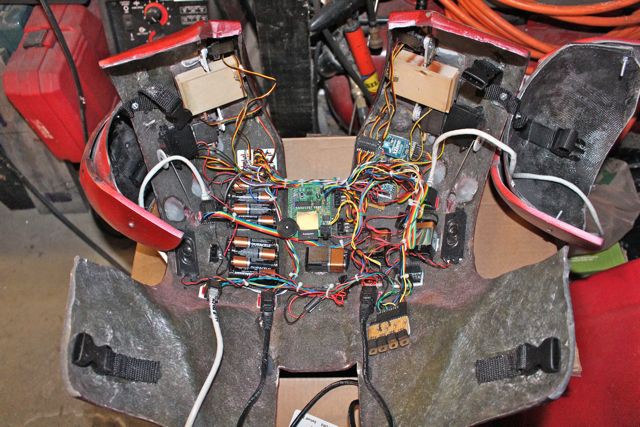
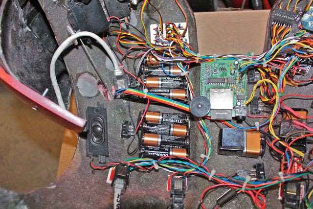
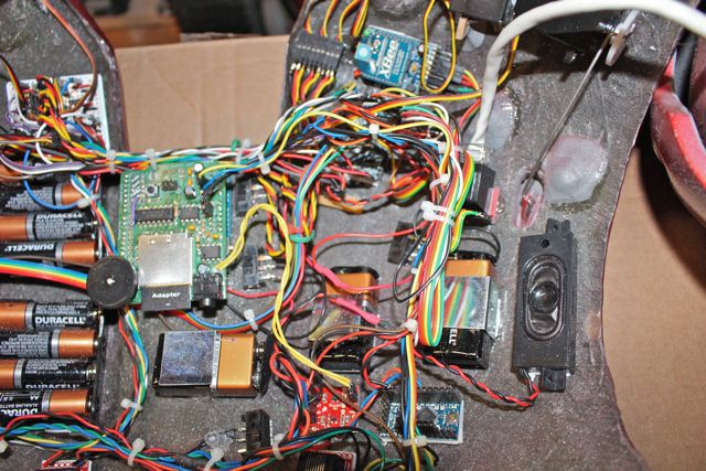
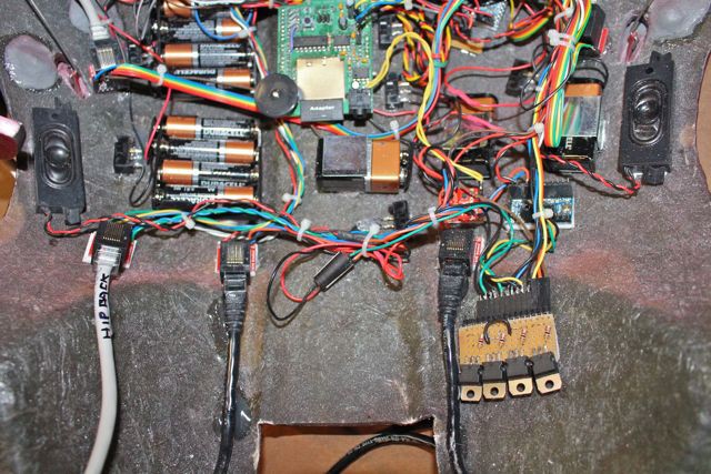
And that is a boatload of wiring! The boards are secured using foam tape as it holds them securely but they can still be removed and if wires get pulled nothing will get damaged. The Ethernet cables were also secured using hot glue a bit away from the connectors in order to provide some strain relief.
If I was to do it again I would probably create a single board down the center and have the Arduinos socketed along with a socketed transistor board using SMD transistors. I would also have the servo connectors on the center board. That would go a log way toward cleaning up the wiring.
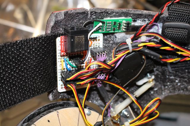
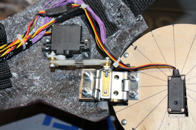
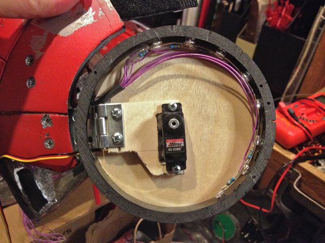
The hip pod section uses a small breadboard PCB with an Ethernet connector to route the signals for the servos and LEDs in the pods. There is a small transistor board that is used to turn on the pod LEDs. The wires fro the LEDs were run through the back of the pods near the hinge and heatshrink tubing was used protect the wires from potential damage caused by hinge movement.
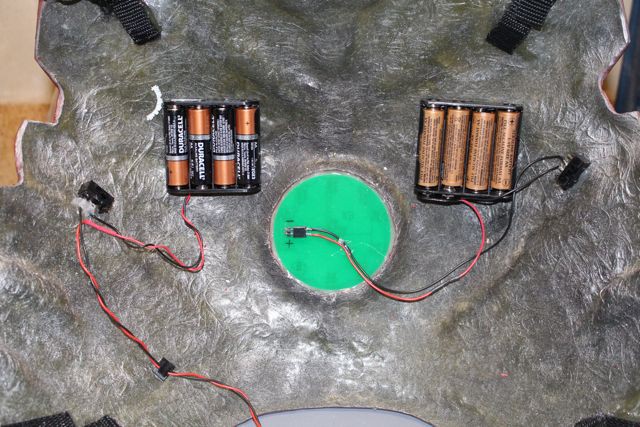
Finally the AA batteries that provide power to the hip pod servos were mounted to the inside of the chest section near the chest light along with a switch. A power lead with a JST connector was run to the hip pod section.
Much to my surprise, everything actually worked the first time it powered up (even though I had breadboarded the circuits for testing.) The only thing I had to do was make adjustments to timing and servo movements in the code.
Discussions
Become a Hackaday.io Member
Create an account to leave a comment. Already have an account? Log In.