jeromekelty
-
Build log 2- forearm missile
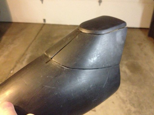
04/22/2014 at 04:59 • 0 commentsOther than the helmet, one of the features we viewed as a "must have" item for the suit was the forearm missile. Much like the helmet, the forearm missile gauntlet has some really tight packaging. There was also the issue that in the film when the gauntlet opens it's done as a visual effect (as are most all of the suit functions.)
We had seen other missile compartments that people had done but they usually only had the top open- we wanted the sides to fold down as well. The other thing we wanted was for the missile pod to open up and back, just like in the movie. And we wanted the missile to extend outward- in for a penny, in for a pound!
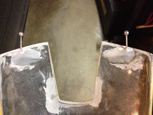
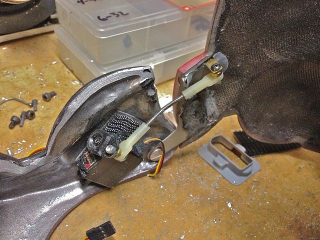
To make the opening compartment the fiberglass gauntlet was first cut apart into the appropriate sections and a plastic base plate was epoxied into the opening. Each of the cut side panels had a 4-40 screw epoxied onto the inside forward point using Propoxy 20. Onto this screw was fitted a swivel link with a rod that was epoxied into the forward section of the gauntlet. This formed a very simple single pivot hinge for the front of each of the side panels.
![]()
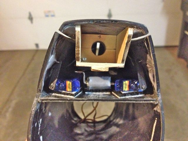
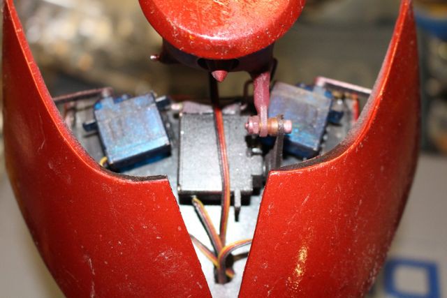
To make the side panels fold down two sub-micro servos had their output arms fitted with a small section of bent music wire that was epoxied to the back of each of the side panels. The servos are attached to the base plate using high strength Velcro. As the servo arms rotate the side panels drop down. A very simple and reliable system.
![]()
![]()
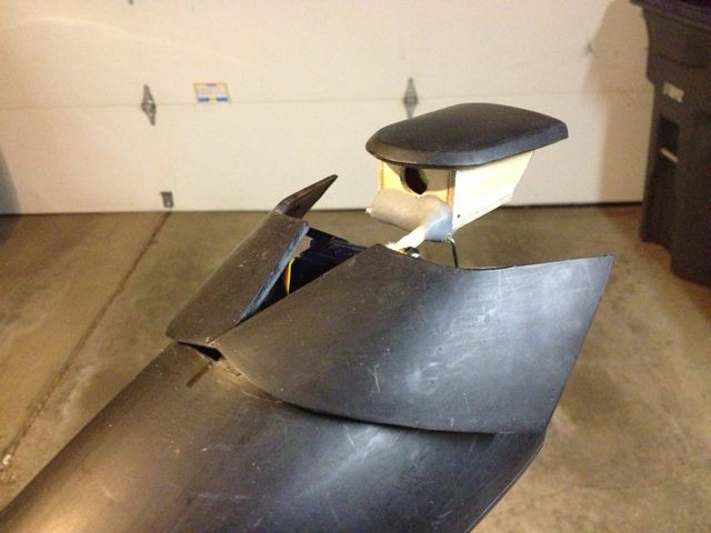
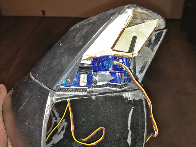
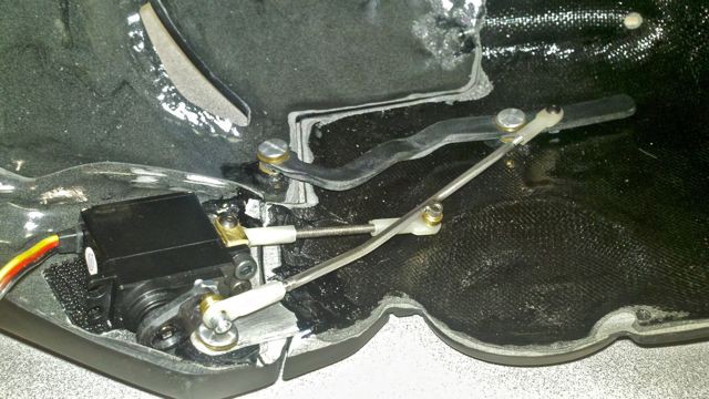
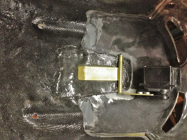
The missile housing was constructed using thin birch plywood sheet. To make the housing move up and back a small parallelogram linkage was fabricated and attached to the micro servo that raises the housing. The servo is attached to the gauntlet base plate using high strength Velcro. The forward hinge uses a 4-40 ball link attached to the plywood housing and the rear link uses music wire that pivots in brass tubes epoxied to both the servo and the plywood housing. The face of the missile housing was built up using Apoxie Sculpt.
![]()
![]()
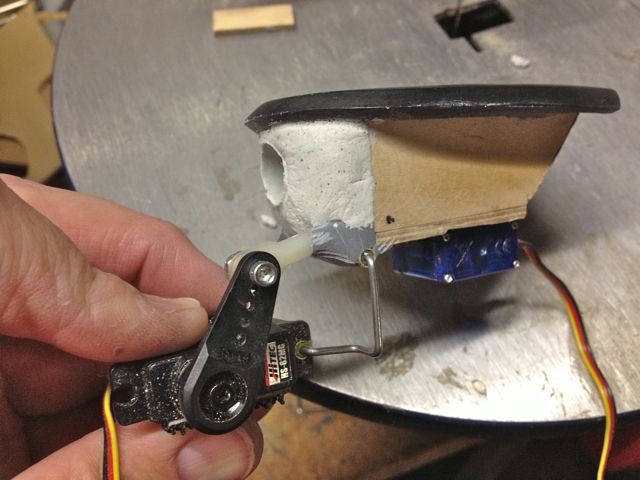
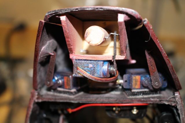
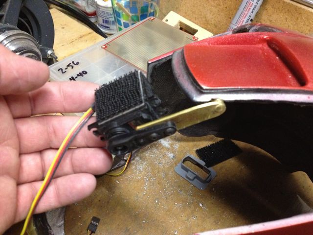
The missile is moved forward in the housing by a sub-micro servo with a long arm. The servo is mounted to the underside of the pod and the arm extends through the bottom of the pod. A short length of music wire is attached to the servo arm and goes through the back center of the missile so as the servo arm rotates the missile extends and retracts through the pod opening. The missile is a short length of wood dowel sanded to shape.
![]()
![]()
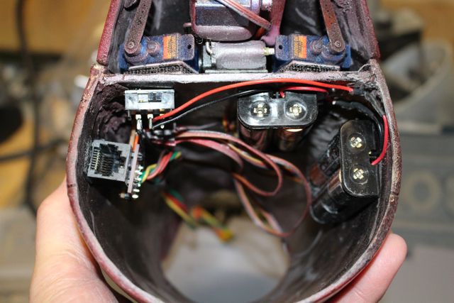
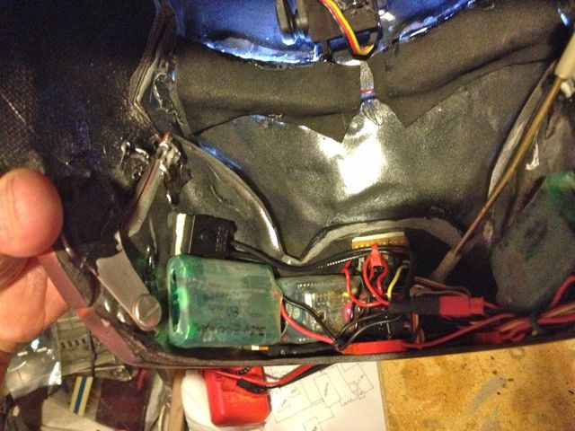
The AA battery holders are held underneath the base plate along with a power switch and an Ethernet connector. The connector is mounted to a small PCB with connectors for the servos and it also has extended wires that reach the gloves. A Ethernet cable runs from the Arduino in the back of suit, down the arm and then connects to the gauntlet. This cable carries the signals for the servos as well as signals and power to the RFID reader in the glove.
![]()
That's a whole lot of hardware in a very small space. Believe it or not his arm fits in there no problem- the opening is a lot bigger than it looks in the photo. The gauntlet worked perfect right out of the gate, which was awesome.
-
Build log 1- wireless helmet
04/22/2014 at 03:27 • 0 commentsFiguring out how to make the helmet work was pretty tricky. We definitely wanted it to be wireless so it could be easily taken off but there's barely any room in the helmet for servos, let alone electronics. When Greg brought the helmet to me it had tracks already molded in the top for two small pivoting links that were attached to the top of the faceplate. The faceplate had two pivoting arms that allowed it to flip up and slide back. The first system that I installed used two identical high voltage digital mini servos with a rod system that moved the faceplate and chin at the same time. As the servos pulled the rods the arms raised the faceplate and a second pivoting rod pushed the chin section open. While this system worked well it was eventually scrapped as it took up too much space around the sides of the helmet, especially in the temple area where the arm pivots were located.
![]()
The revised system works a bit different and is much simpler. I altered the original helmet system by changing it from a multi link/multi pivot system to a simple three pivot system. The arms that lifted the faceplate were removed as were their four pivots. The tracks in the top of the helmet were kept but the links had a tendency to bind as they pivoted so the links were reconstructed from scratch as fixed points and epoxied to the top of the helmet faceplate using ProPoxy 20 epoxy putty in a fixed position.
![]()
The servo mechanism was changed so one servo would open the faceplate while another would open the chin- that way the timing could be changed so the faceplate would open first and then the chin would open. When closing the helmet the chin would close first, then the faceplate. The faceplate servo has a brass arm that is silver soldered to a hinge that is fiberglassed into the top center section of the helmet. The brass plate that is soldered to the hinge tube is extended back a ways in order to support the helmet section as it would otherwise be too flexy to work properly. Both of the servos were attached to the helmet using high strength Velcro.
![]()
![]()
The chin servo was swapped out for a slightly smaller servo and it pushes a 4-40 threaded rod that opens the chin section- it's a pretty simple arrangement. Eventually the chin servo was relocated closer to the center of the chin piece to make more room for one of the battery packs.
![]()
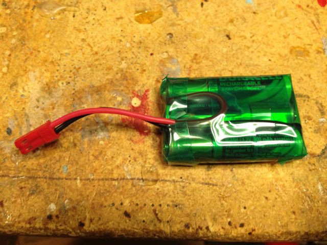
On the electronics side, a split battery pack was constructed using six AAA NiMH cells for a total of 7.4V to power the high voltage digital servos. Originally we had planned on using LiPo packs but felt that NiMH cells would be a lot safer and less hassle in terms of battery management.
![]()
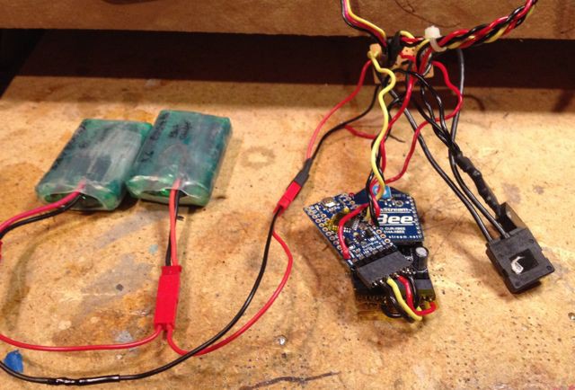
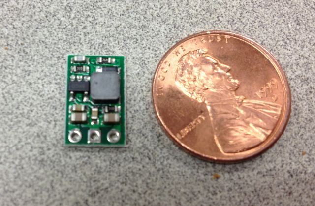
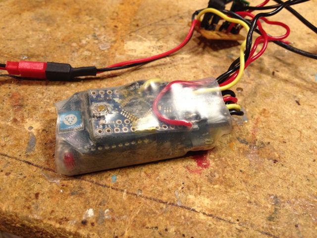
The two battery packs were wired up to an Arduino ProMini (3.3V version) along with a XBee radio. Power to the ProMini was stepped down to 5V using a Pololu DC/DC converter. The electronics were covered with heat shrink for protection.
![]()
![]()
![]()
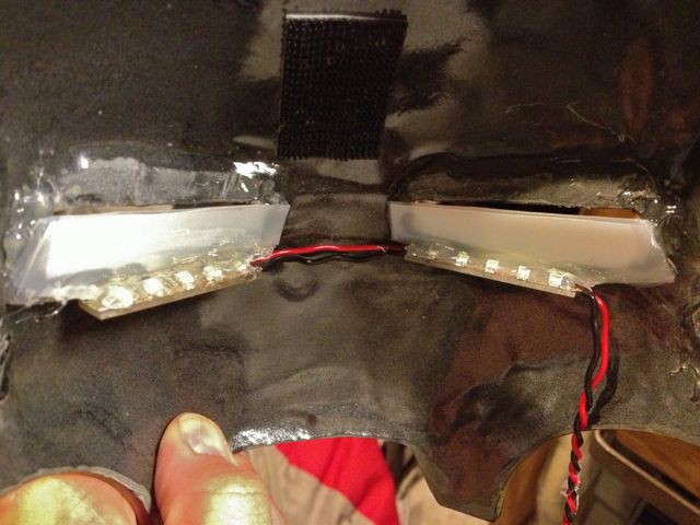
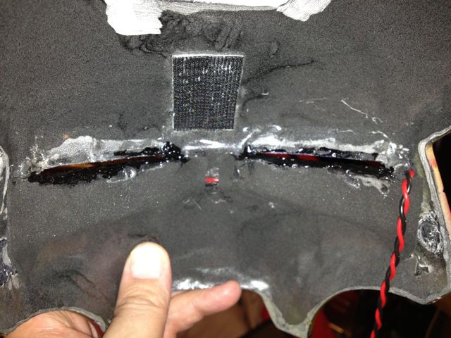
A sealed push button power switch was added along with a transistor to turn on the LED lights for the eyes. The eyes were constructed using SMT LEDs with milk jug material being used for the lenses. The lenses have a slit at the top so the wearer can see out and black foam sheet as used to block out the light on the inside of the helmet.
![]()
![]()
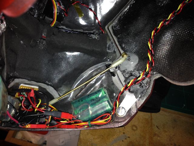
Finally all of the electronics were secured in the chin section of the helmet. Everything just barely fit in there without being able to be seen when the helmet is open.
![]()
![]()
Overall we're very pleased with how the helmet turned out. It opens very quickly and we can change the speed of the servos along with the timing of the opening/closing sequence very easily.
Animatronic Iron Man MKIII suit
RFID tags in the gloves control shoulder rockets pods, hip pods, forearm missile, back flaps and wireless helmet.