 Tony Kambourakis
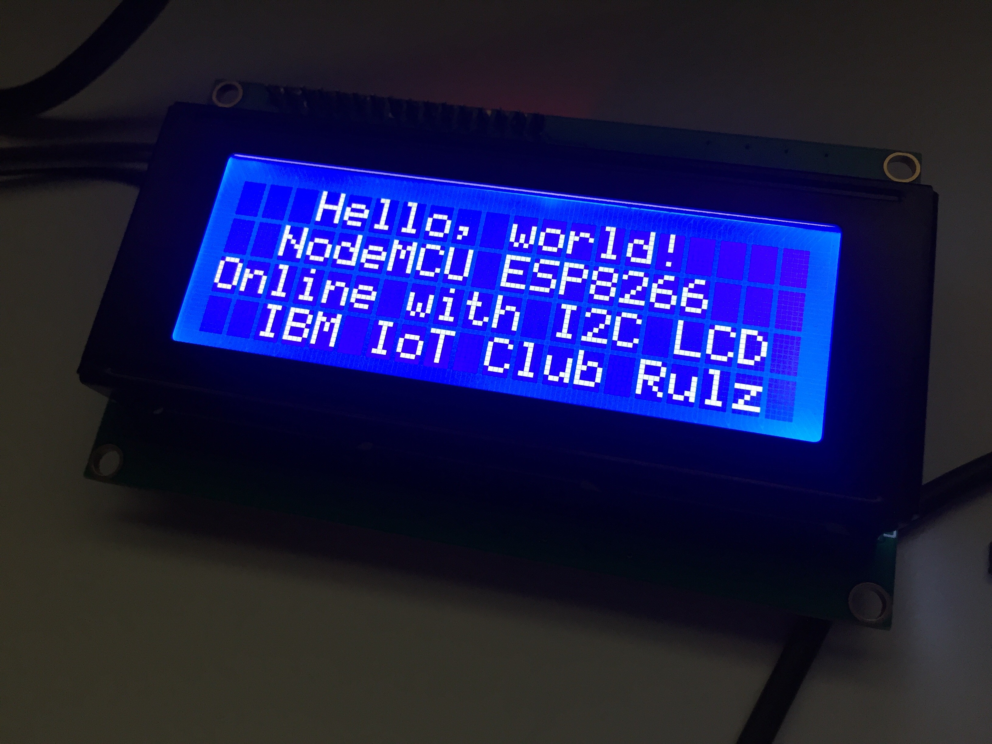
Established I2C link to TWI 2004 204 20x4 LCD module from the ESP8266. The ESP8266 port for Arduino thankfully includes an I2C implementing in the Wire library.
The only additional library required for working with the LCD is LiquidCrystal_I2C by Marco Schwartz (Version 1.1.0). This is accessible via the Arduino IDE Library Manager.

A slight modification of this library is also required to map it to the NodeMCU Amica DevKit pins that I connected the LCD to. Once the library is installed open the LiquidCrystal_I2C.cpp file located in the libraries folder. On a mac it is located in
~/Documents/Arduino/libraries/LiquidCrystal_I2C
The necessary update is included below:
void LiquidCrystal_I2C::init_priv()
{
	Wire.begin(2,14); // was originally Wire.begin();
	_displayfunction = LCD_4BITMODE | LCD_1LINE | LCD_5x8DOTS;
	begin(_cols, _rows);
}
2, 14 represent GPIO2 and GPIO14. On the NodeMCU Amica they are physically pins D4 and D5. The code to display text on a 4 line display is as follows:
#include <Wire.h>
#include <LiquidCrystal_I2C.h>

LiquidCrystal_I2C lcd(0x27,20,4);  // set the LCD address to 0x27 for a 20 chars and 4 line display

void setup()
{
  lcd.init();                      // initialize the lcd
  lcd.init();
  // Print a message to the LCD.
  lcd.backlight();
  lcd.setCursor(3,0);
  lcd.print("Hello, world!");
  lcd.setCursor(2,1);
  lcd.print("NodeMCU ESP8266");
   lcd.setCursor(0,2);
  lcd.print("Online with I2C LCD");
   lcd.setCursor(2,3);
  lcd.print("IBM IoT Club Rulz");
}


void loop()
{
}
The initialisation of the LiquidCrystal_I2C object includes a HEX address of the LCD I2C controller that is attached to he back of the LCD. It can be discovered using scanner code by Nick Gammon (site includes a great primer on I2C) . The code is included below:
// I2C Scanner
// Written by Nick Gammon
// Date: 20th April 2011
#include <Wire.h>
void setup() {
Serial.begin (115200);
// Leonardo: wait for serial port to connect
while (!Serial)
{
}
Serial.println ();
Serial.println ("I2C scanner. Scanning ...");
byte count = 0;
Wire.begin();
for (byte i = 8; i < 120; i++)
{
Wire.beginTransmission (i);
if (Wire.endTransmission () == 0)
{
Serial.print ("Found address: ");
Serial.print (i, DEC);
Serial.print (" (0x");
Serial.print (i, HEX);
Serial.println (")");
count++;
delay (1); // maybe unneeded?
} // end of good response
} // end of for loop
Serial.println ("Done.");
Serial.print ("Found ");
Serial.print (count, DEC);
Serial.println (" device(s).");
} // end of setup
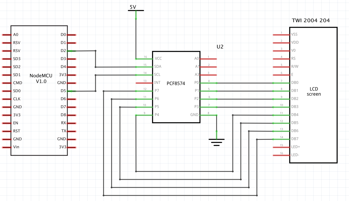
void loop() {}The schematic
Discussions
Become a Hackaday.io Member
Create an account to leave a comment. Already have an account? Log In.
"2, 14 represent GPIO2 and GPIO14. On the NodeMCU Amica they are physically pins D4 and D5."
now look your schematic... I do this, won't work
Are you sure? yes | no
Try connecting NodeMCU D4 instead of D2 to the PCF8574 SDA pin. I think the schematic is incorrect.
Are you sure? yes | no
won't work...
I do: https://www.losant.com/blog/how-to-connect-lcd-esp8266-nodemcu
Work.
Are you sure? yes | no