 Tony Kambourakis
The ESP8266 (ESP-12E), the core of the NodeMCU devkit, requires a 3.3V supply. The GPIO pins also supposedly operate at 3.3V logic levels. This can be confirmed with the NodeMCU DevKit official documentation:
不得对开发板输入超过 5V 以上的电源电压,也不得将开发板 GPIO 直接连接到 5V 电平的外设上。如果需要连接,需要电平转换电路,否则可能造成不可逆转的损坏。
The board shall not enter more than 5V supply voltage, nor will board GPIO directly connected to 5V level peripherals. If you need to connect
Then, we need to level conversion circuit, or it may cause irreversible damage.
The NodeMCU documentation is light on but it seems that the board is typically supplied with 5V either via the VIN pin or the USB socket. Supplying power directly to the 3.3V pins also powers up the MCU but driving the LCD that way results in a very dim LCD output even at maximum brightness setting with a current consumption by the LCD of around 6 mA. When powered at 5V the LCD consumes around 20 mA.
The required supply voltage for the LCDs (4-line and 2-line) I have been using state 5V even though they comprise the HDD44780, which requires a supply voltage of 2.7V to 5.5V, and the I2C's PCA8574, which can operates at 2.3V to 5.5V (HIGH-level input voltage is 0.7VDD min and 5.5V max).
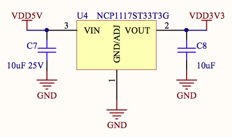
The NodeMCU DevKit includes an NCP1117 regulator that takes 5V in and supplies the ESP-12E with 3.3V.
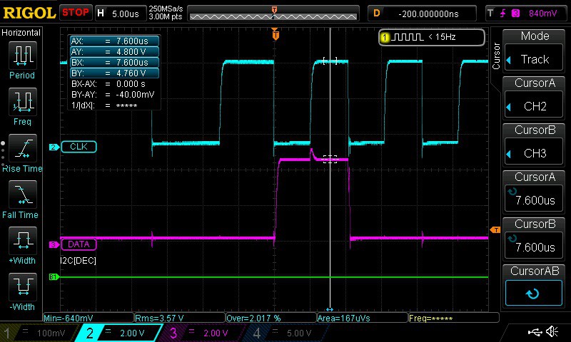
Interestingly if the NodeMCU is powered by 5V and drives the LCD via I2C directly the SDA/SDCL levels measure around 4V! At this level it satisfies the 0.7VDD requirement of the PC8574 (0.7 x 5 = 3.5V) on the LCD. In this case the LCD is supplied with 5V off the power supply. As seen in the scope image below, the SCL high level is 4.92V and the SDA (DATA) high level is 4.08V.
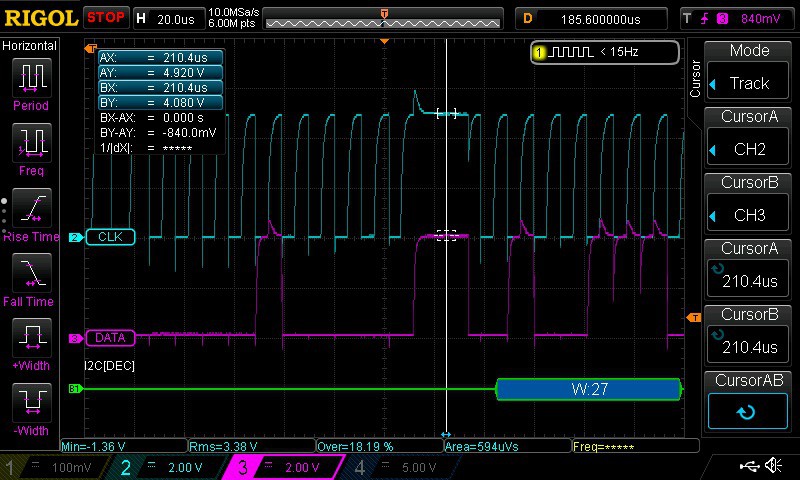
How does that Node MCU GPIO output get to 4.92V when the ESP-12E is powered by 3.3V? Why is the SDA level only 4.08V and the SCL level at 4.92V?
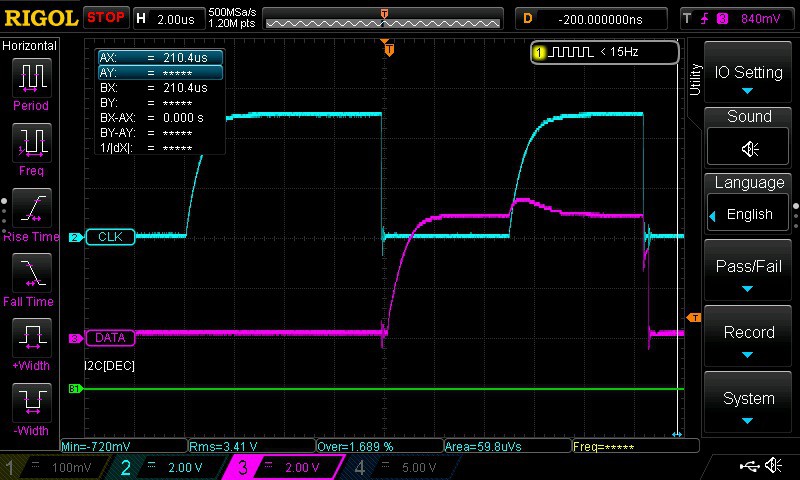
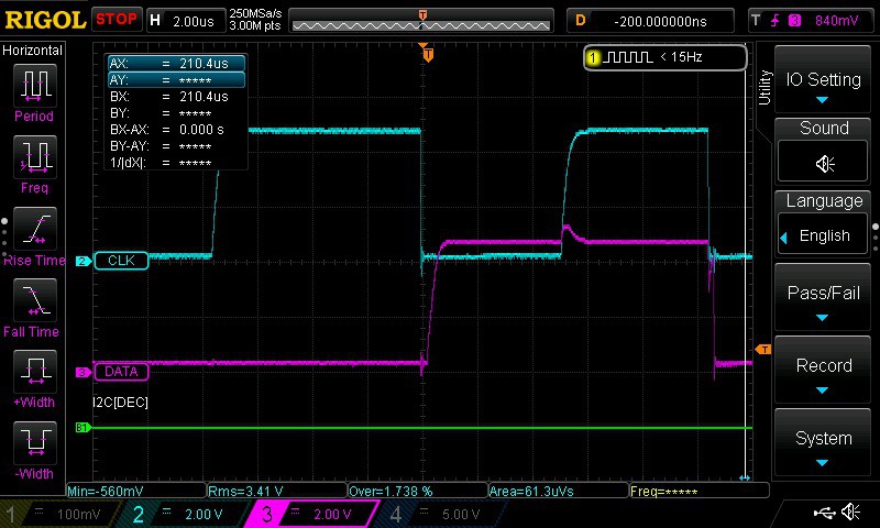
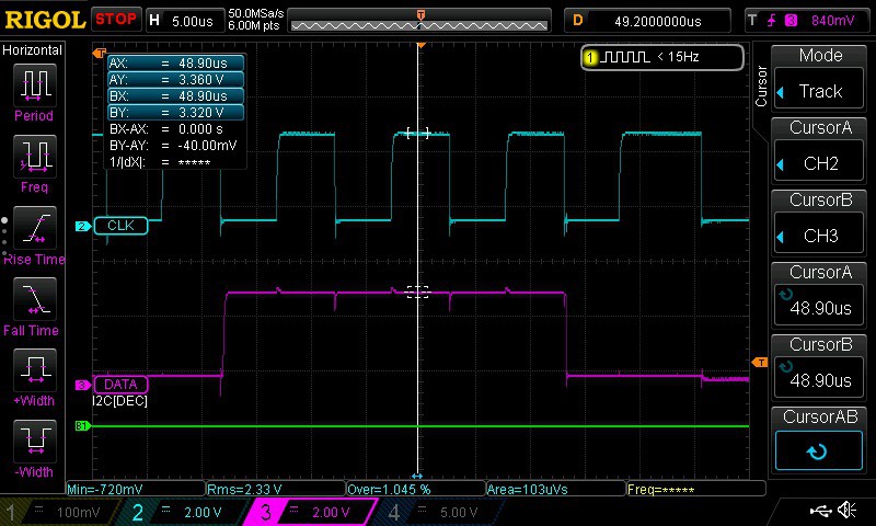
I suspect it has something to do with the PCA8574 pulling high perhaps due to an internal pull up resistor either on the NodeMCU or 8574. The slow rise time of the SCL and DATA signals also indicate the use of an internal pull up resistor as an external pull up had not been used yet. The scope shot below shows the slow rise time.
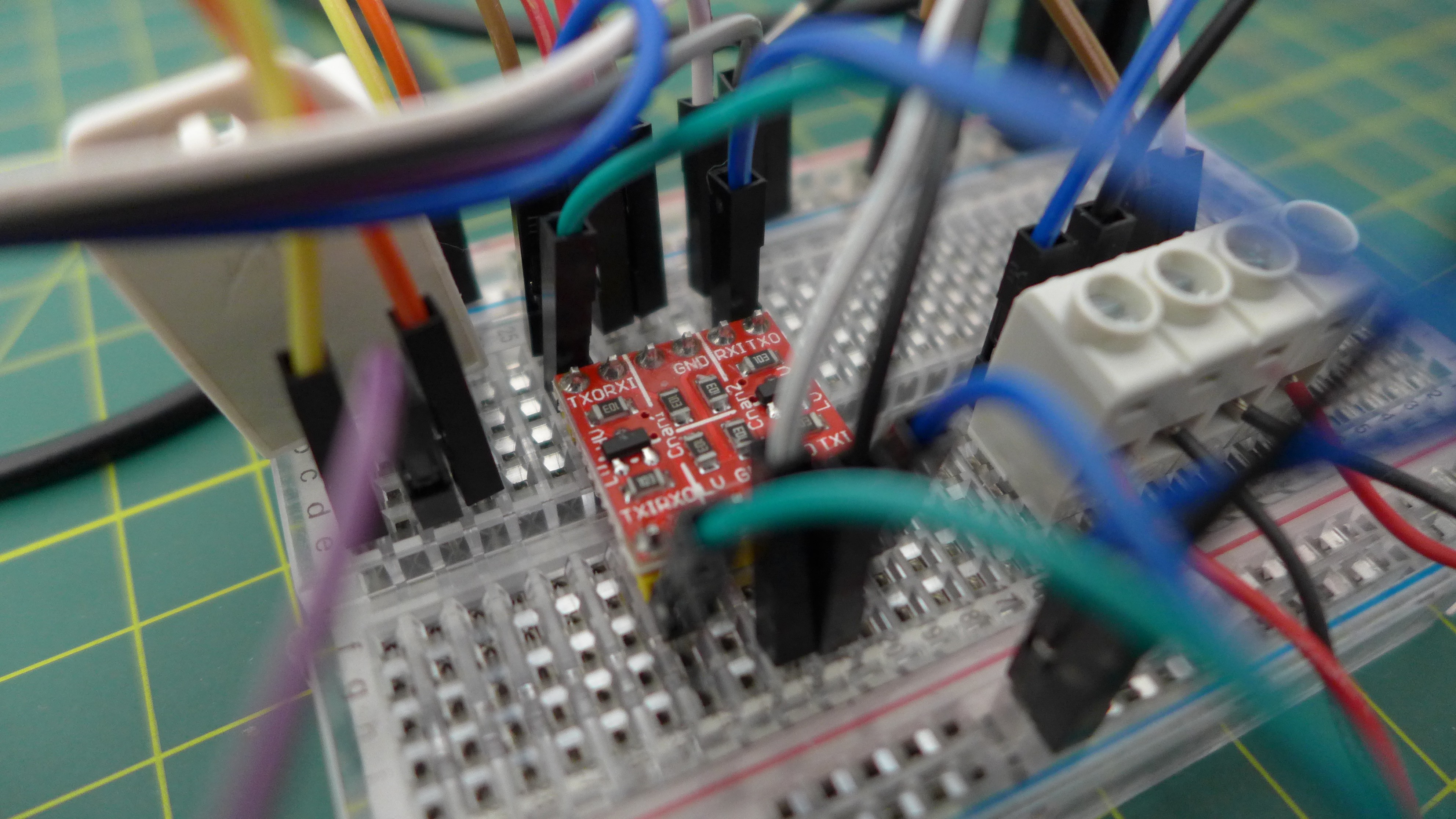
A level shifter (Duinotech Logic Level Converter Module from Jaycar which is a rebadged SparkFun module) was also introduced to increase the voltage levels of the SDA and SCL signals. The scope shot below shows the SCL at 4.8V and the SDA at 4.76V.
There isn't much difference in what is displayed on the LCD with the level shifter. The SDA/SCL levels on the MCU side of the level shifter have dropped back to 3.3V. Pull up resistors were also added to the MCU side of SDA/SCL.
The level shifter:
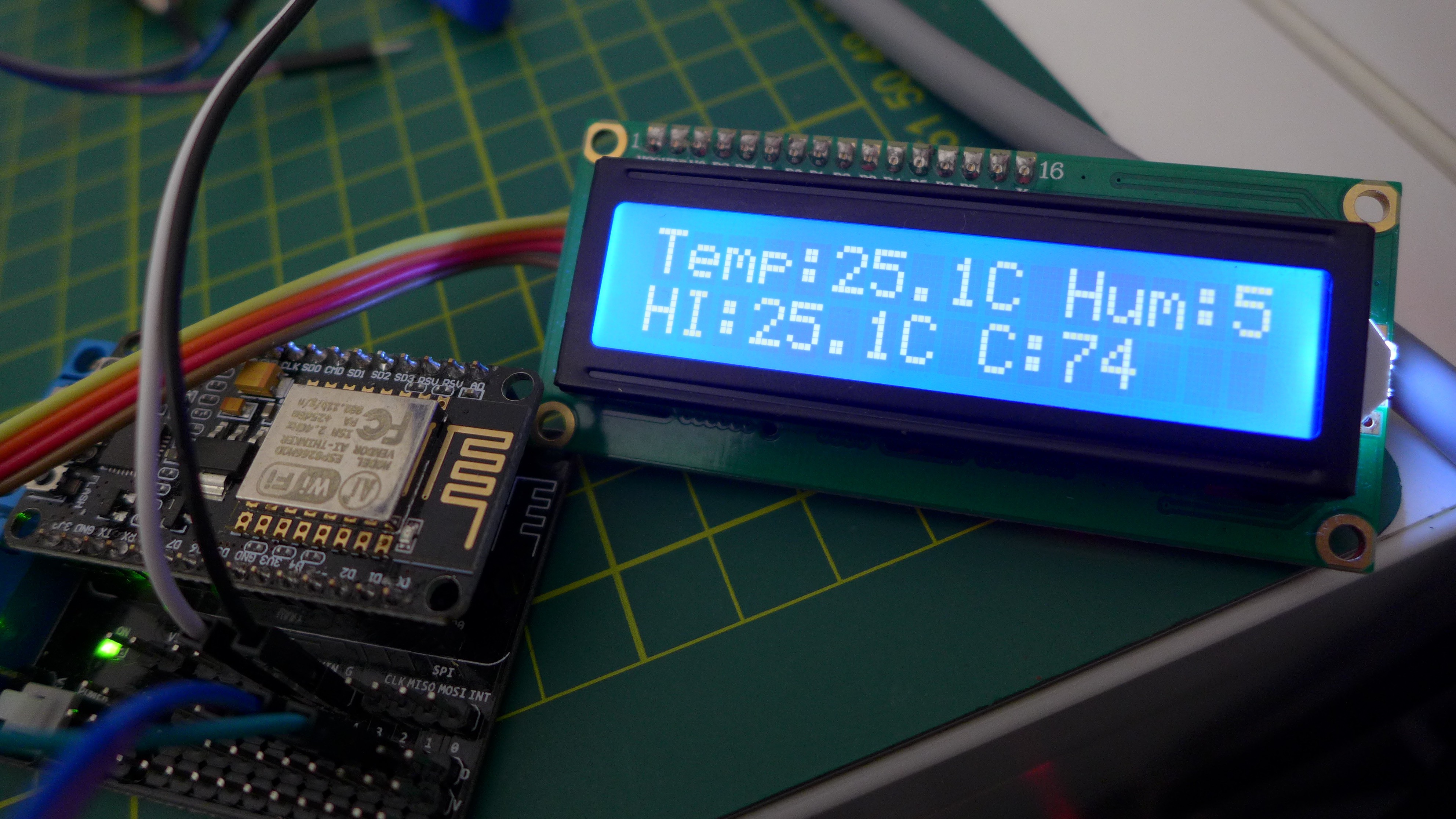
Reading temperature and humidity (and heat index) from the DHT22 and displaying on LCD (along with counter "C") - yep, the humidity is cut off. I'll be using the larger 4-line display.
Discussions
Become a Hackaday.io Member
Create an account to leave a comment. Already have an account? Log In.