I Did This To Myself...
So I placed an order with OSH Park for the PCBs on January 13th and I wasn't expecting them to be here so soon!
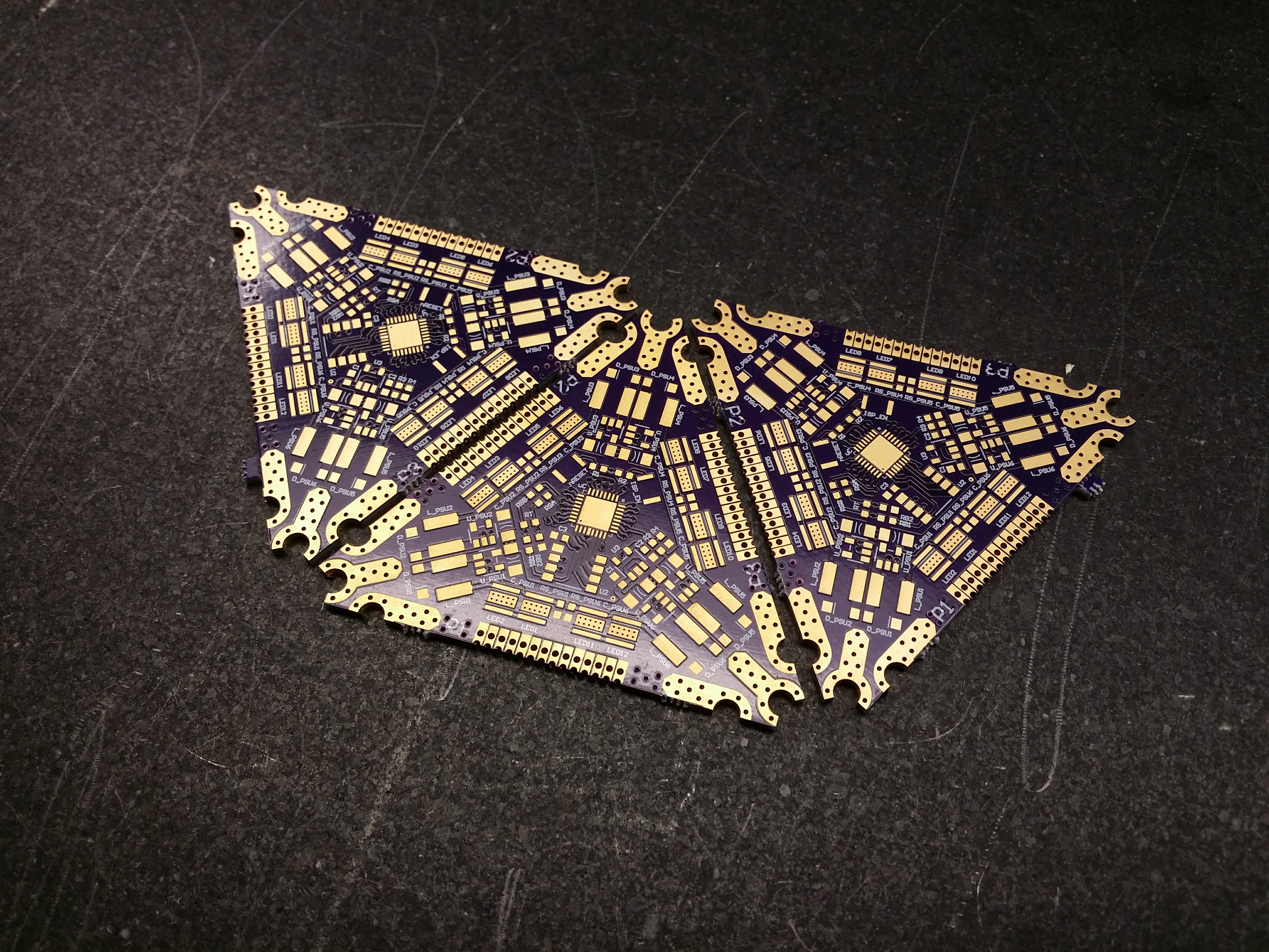
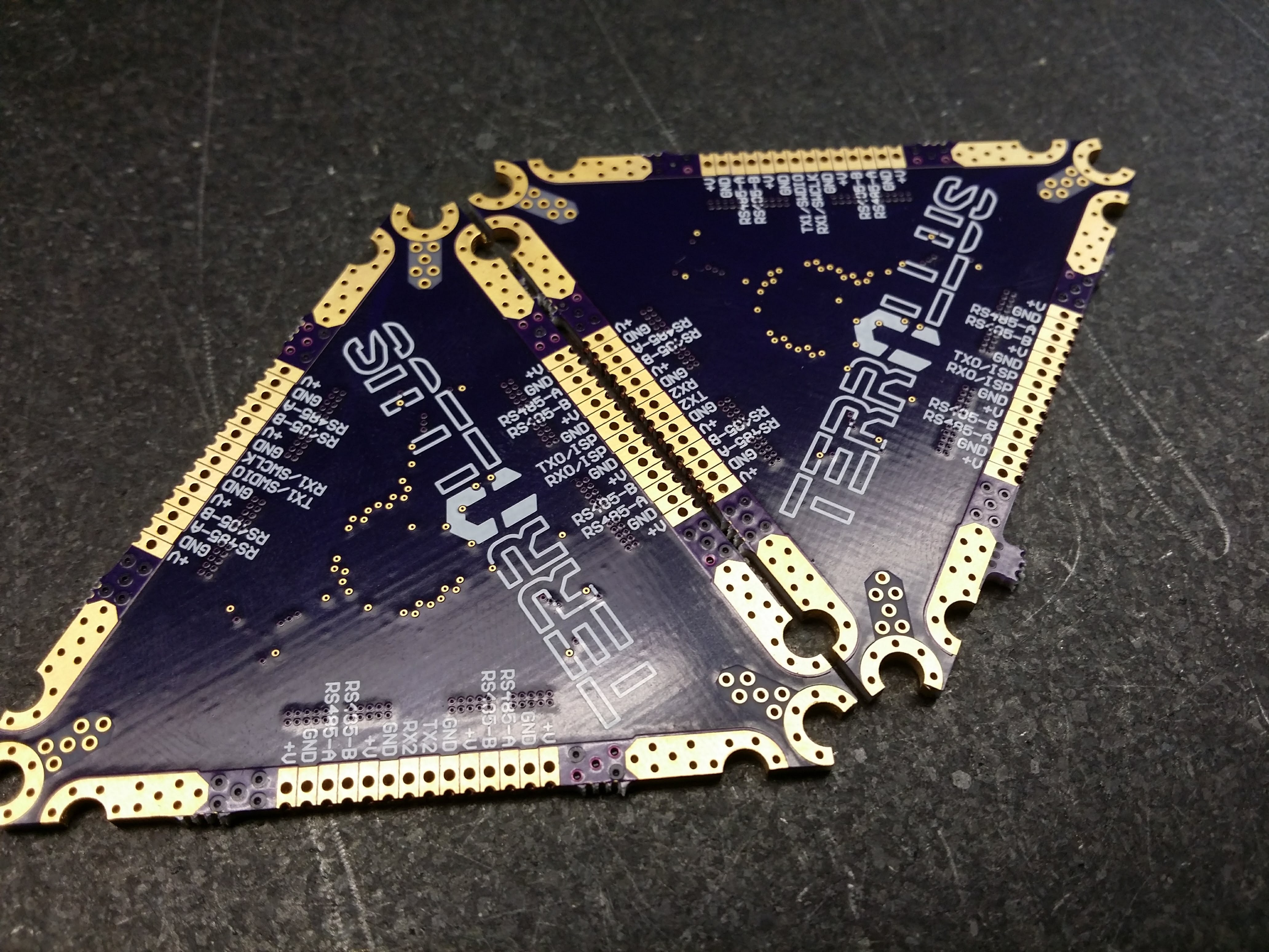
The silkscreen turned out fabulous; the soldermask and hole registrations are VERY good. And then I noticed something...
If you look carefully at the soldermask in Figure 2, notice the lack of copper pads where the ground pads and screw pads are. A quick continuity check further confused me as all the IO connections were shorted together along with the power pads on the side and the corner ground pads.
Looking further at Figure 2, you can see that the vias seem raised and bumpy. The same can be said about the power pads and IO connectors. Compared to Figure 1, all seems well on the top side of the board.
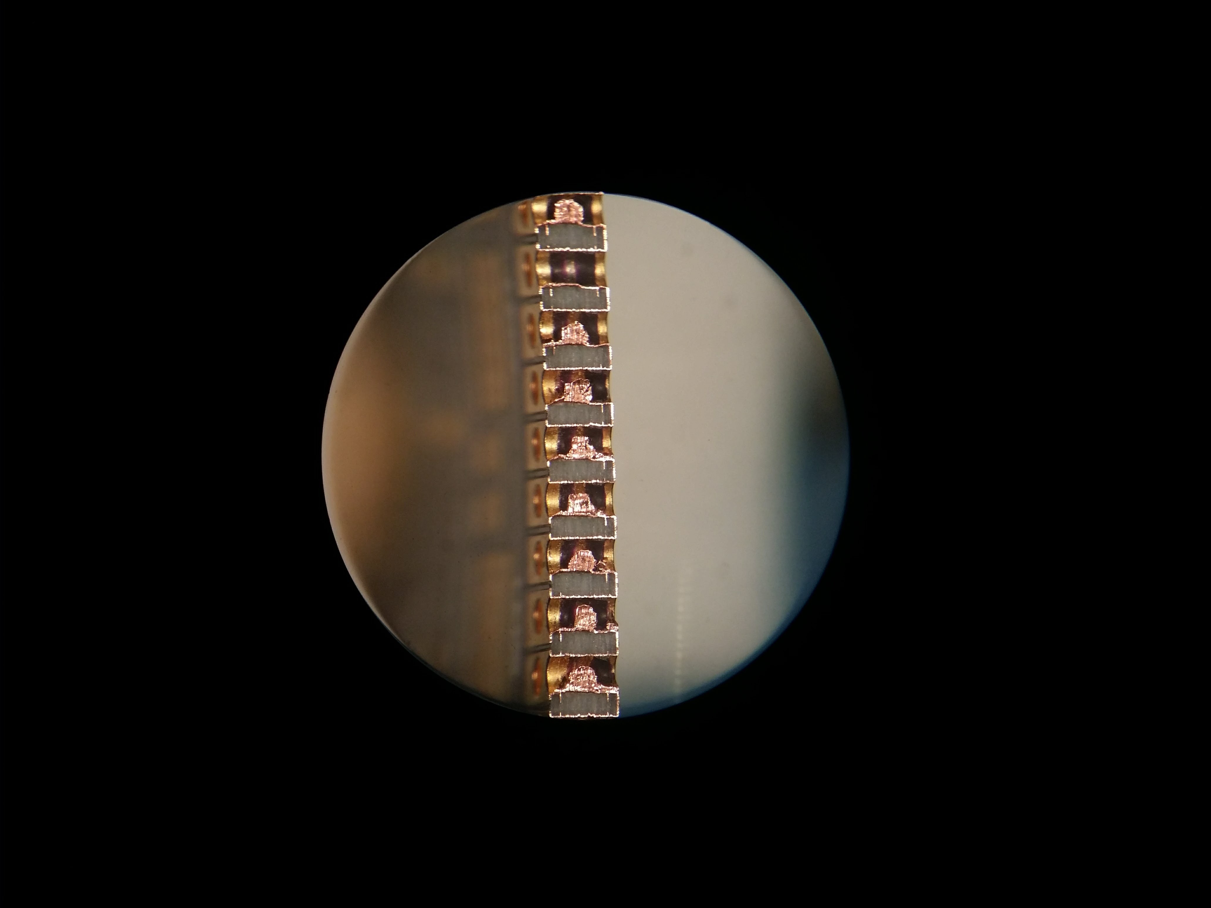
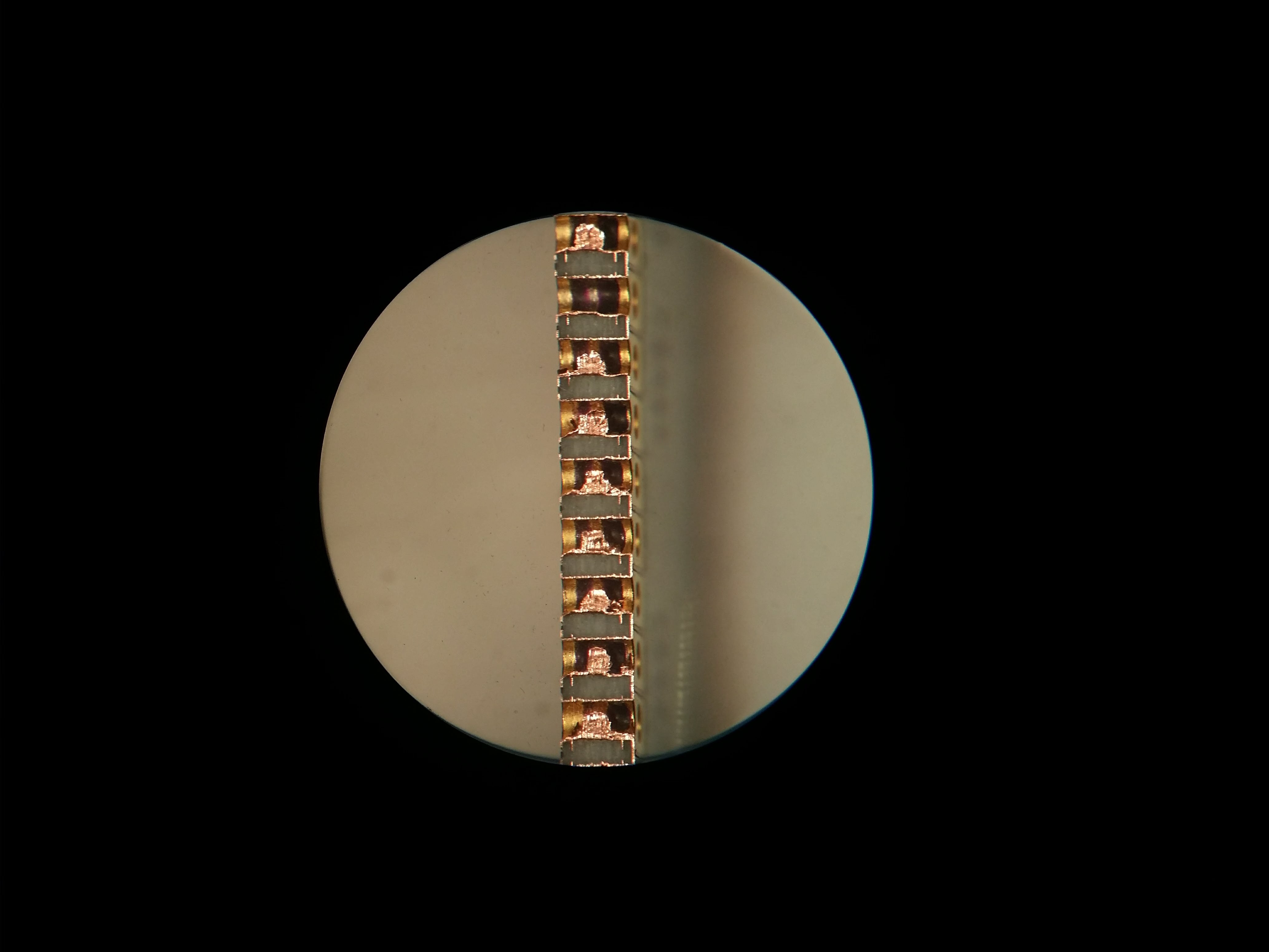
A quick look under the inspection scope shows a potential problem in the IO connector. Figure 3 shows the top side (LED side) on the left and in focus. Figure 4 shows the bottom side on the right and in focus. The IO pads seem to be connected on the bottom layer and on the top they are isolated as they should be. Also of note are the internal layers visible in both inspection pictures.
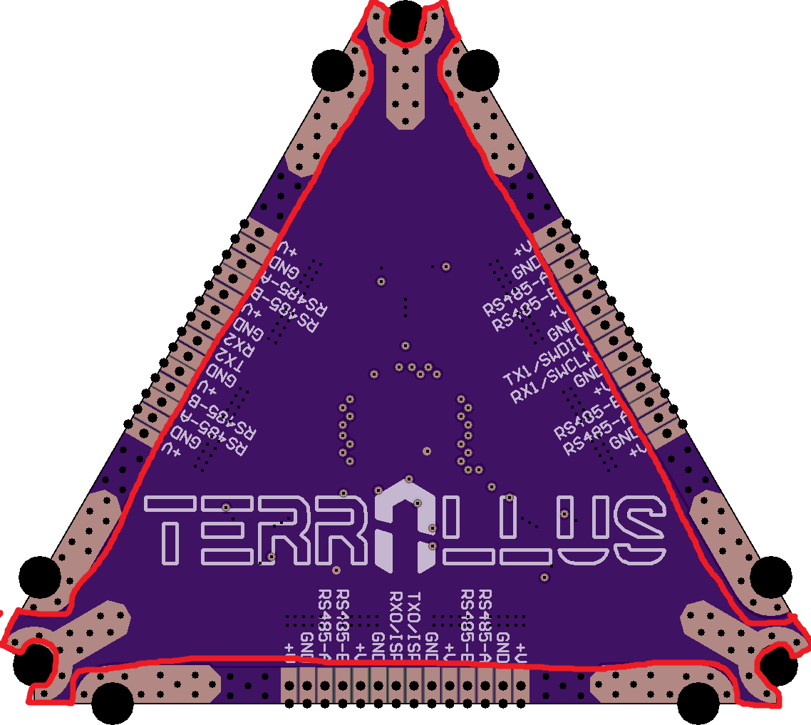
It seems that the ground plane on the bottom later is entirely missing (as outlined in Figure 5). However, the IO connector pads are all shorted together. Weird...
The Fix...
I informed OSH Park about the issue and their response was quick and quite unexpectedly detailed. They were so awesome in fact that they dug deep to figure out the problem and over the weekend at that! It turns out it was partly my fault although I didn't know it at the time.
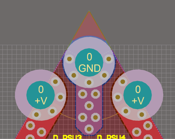
The internal planes were initially setup as an equilateral triangle but my board outline cut through them. This meant that there were parts of the planes outside the board as shown in Figure 6 (top portion of plane visible above and past the center "GND" screw pad). When the gerbers were processed by OSH Park, the over extending parts of the plane were removed. However because they are part of the same plane entities, the entire plane was removed and funkiness ensued.
The folks at OSH Park were very thorough in their investigation and offered a very concise explanation in a timely manner. They were nice enough to rerun the boards for me at no cost and even offered expedited shipping!
Thank you OSH Park!
OSH Park, thank you very much for the help. I learned something new and I hope other companies follow your lead...
 slisgrinder
Discussions
Become a Hackaday.io Member
Create an account to leave a comment. Already have an account? Log In.