 slisgrinder
Reruns received...
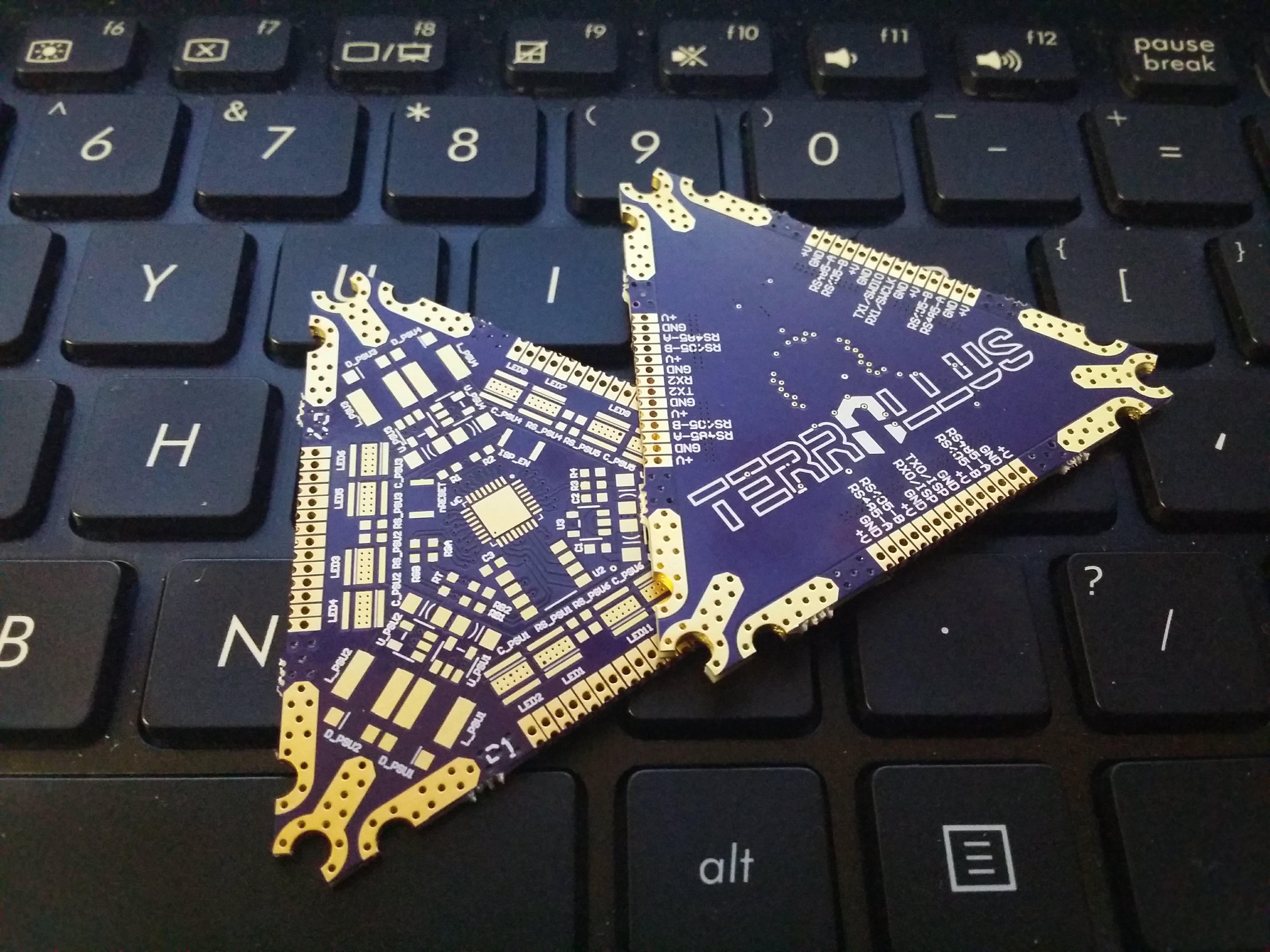
I received the reruns from OSH Park and they look beautiful!
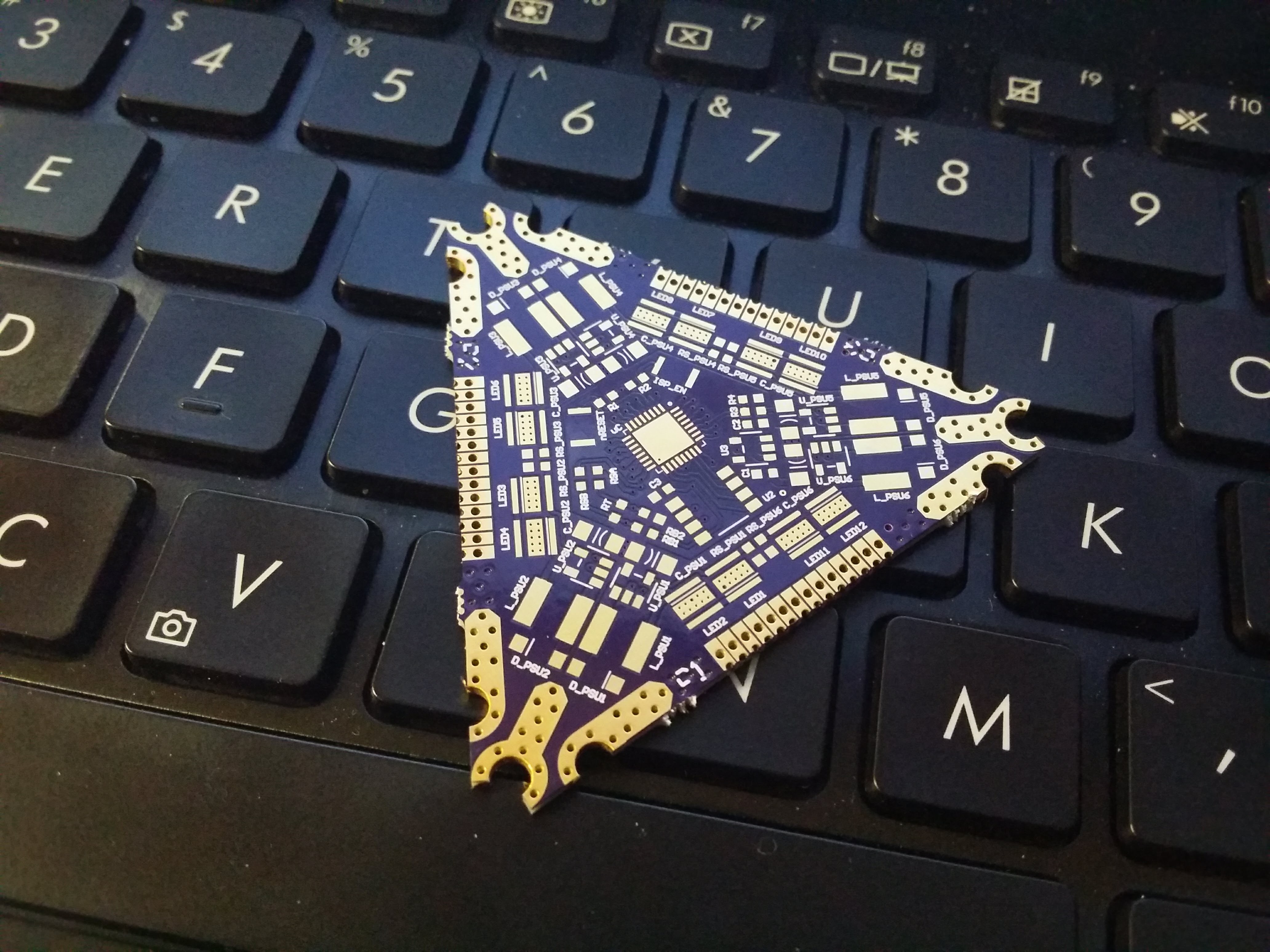
Top side looks great, just like the previous run.
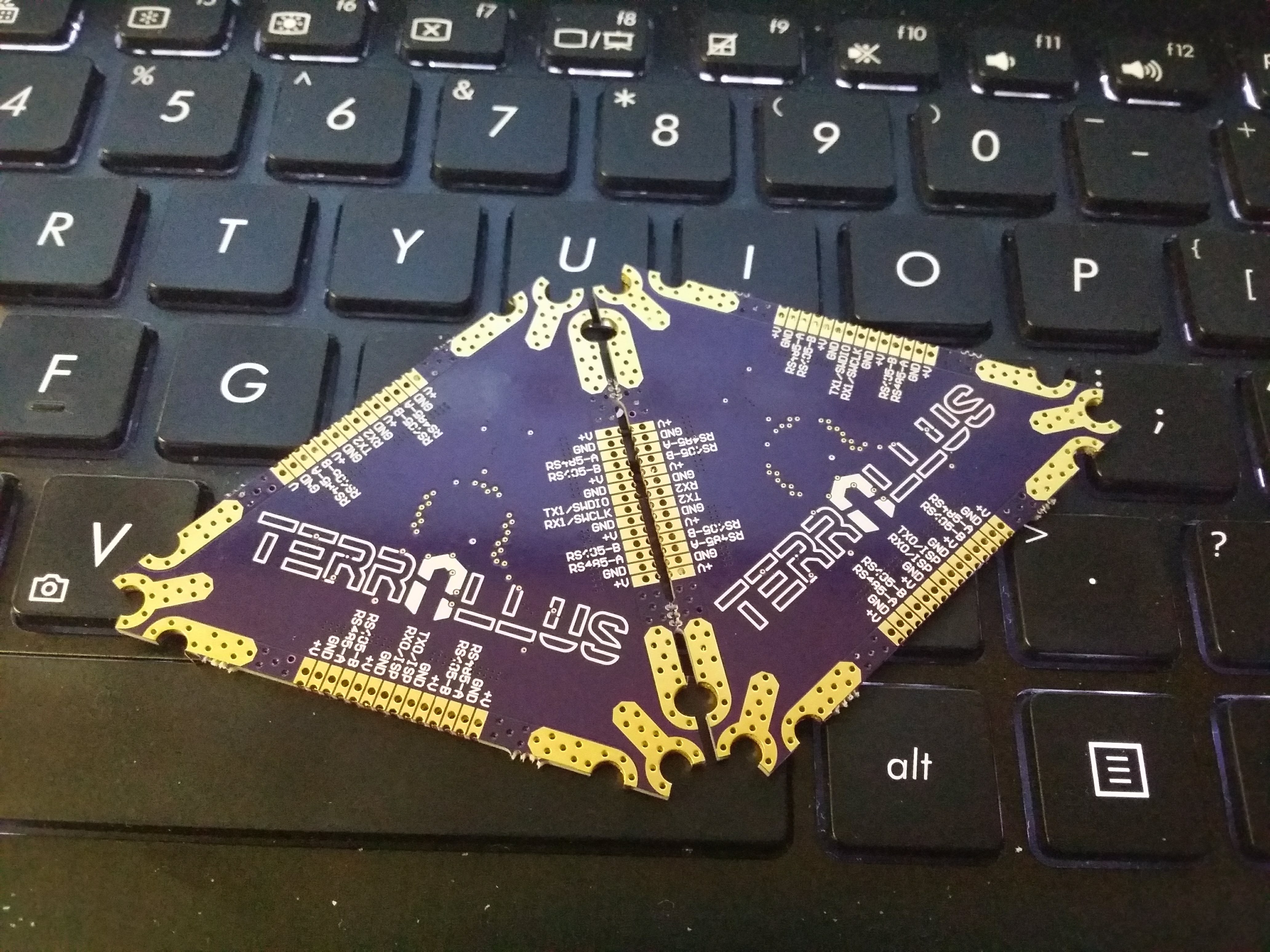
And, the back side looks as its supposed too!
A quick continuity test reveals that all is well and that all the internal layers are intact.
Hot test...
After a quick order on DigiKey, I received the parts and began the reflow soldering of the LEDs and their respective buck converters. The LEDs were the most difficult part because I didn't want to damage the LEDs by using the hot air pencil above them.
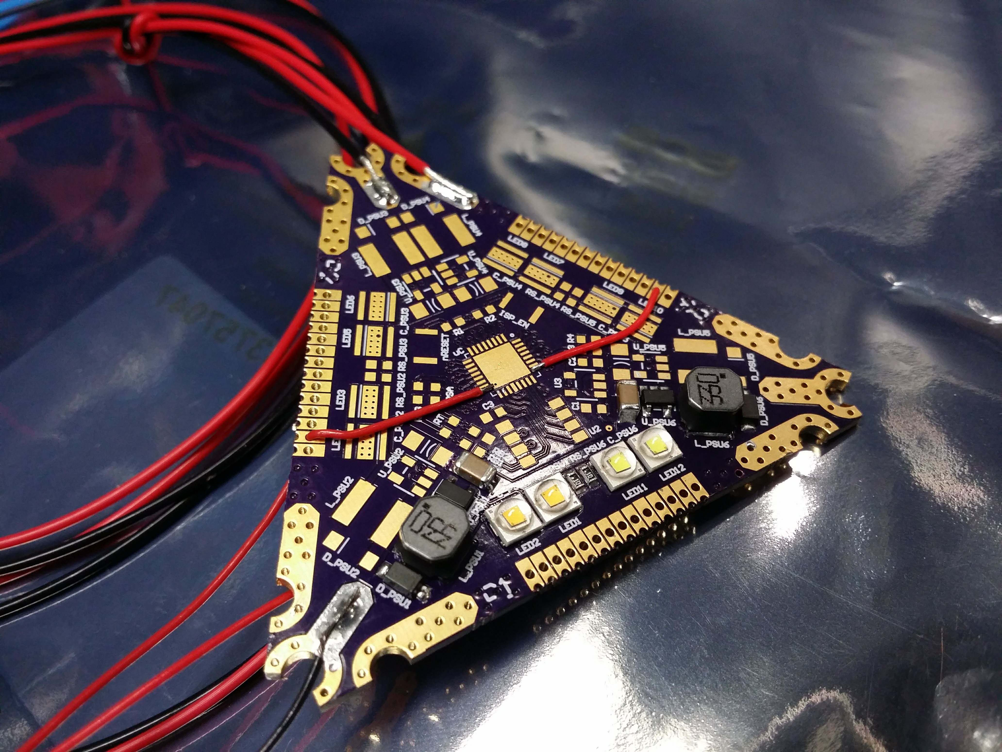
I also ended up just soldering wires to the micro controller pads that are supposed to be the PWM outputs to the buck converter. This way I can test it using another microcontroller board or in my case a function generator.
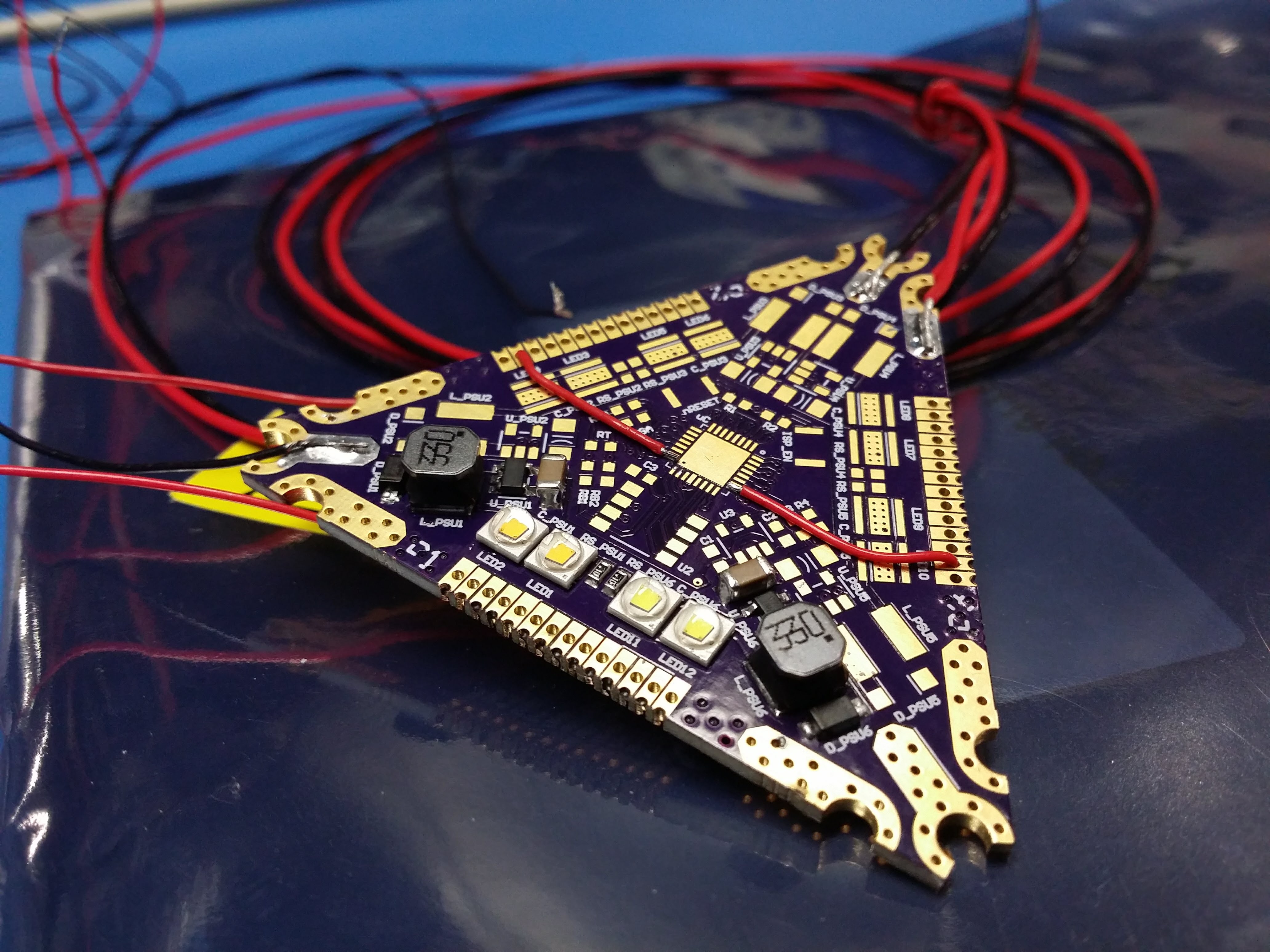
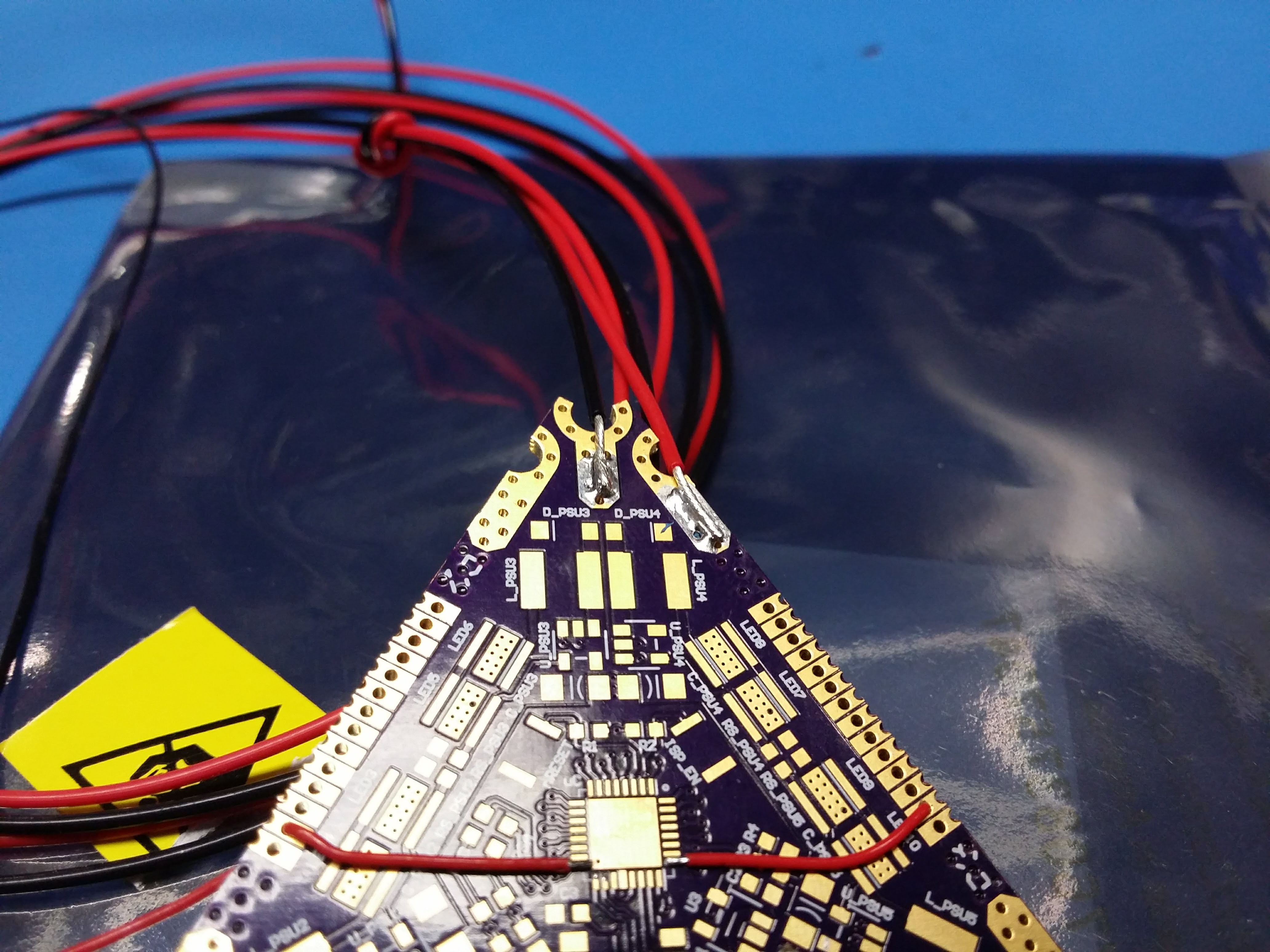
In case it wasn't clear about how to power the board, Figure 6 shows how the screw and wire combination power pads are used.
Hot problems...
Unfortunately I wasn't able to pictures of the circuit in operation because I ran into some problems. First off, holy crap are these bright! At first I was only able to the the 2700K LEDs working but after a quick reflow to ensure all the LEDs had settled, the 5700K turned on. As bright as they are, they also get hot very quickly, thus I wasn't able to run them long enough to take a picture. This heat was somewhat manageable at a PWM duty cycle of 20% @ 100Hz but even then I could only run them for no more than 10 seconds. I suppose the next order of business is to look at heat sinking and some temperature measurements.
Some quick measurements confirmed that the LEDs are consuming just under 6W per pair. Each cell has 6 pairs of LEDs so that means I am going to have enough heat to desolder the LEDs. Fun...
Then I did the stupid thing... I increased the supply voltage up to 24V and then all the LEDs turned off. I went over the reverse bias voltage causing them to short for a fraction of a second and then fail in the open. I have already made the necessary changes to the BOM so that all components can withstand the rated 40V input.
As an aside, while I was troubleshooting what happened to the diodes, I came across a PCB layout error. The footprint of the LDO linear regulator used for the microcontroller power was incorrect. I switched a couple of pins around probably when I was looking at some other part. In any case, the issue has been resolved, new gerbers were produced with the corrections recommended by OSH Park and they should be on their way to me soon. I also ordered a stencil from OSH Stencil so that should be exciting...
Discussions
Become a Hackaday.io Member
Create an account to leave a comment. Already have an account? Log In.