 Nick Sayer
One thing I discovered trying to troubleshoot the new design for the voltmeter was that the secondary side was wired backwards. I lifted the two pins and swapped them with wires, but it still didn't work. It's possible that the period of time it was in circuit miswired was enough to blow the phototransistor. Not sure.
I ordered two new boards from OSHPark for testing. One with the same circuit (but with the mistake fixed) and the other with the other type of circuit from the IXYS application note. I would much prefer the Photovoltaic variant rather than the Photoconductive because the former has much better linearity and accuracy at the cost of reduced bandwidth (but bandwidth here doesn't matter).
Turns out both work, so I'm going with the photovoltaic variant. When powered with 120VAC, the output on the scope looks like this:
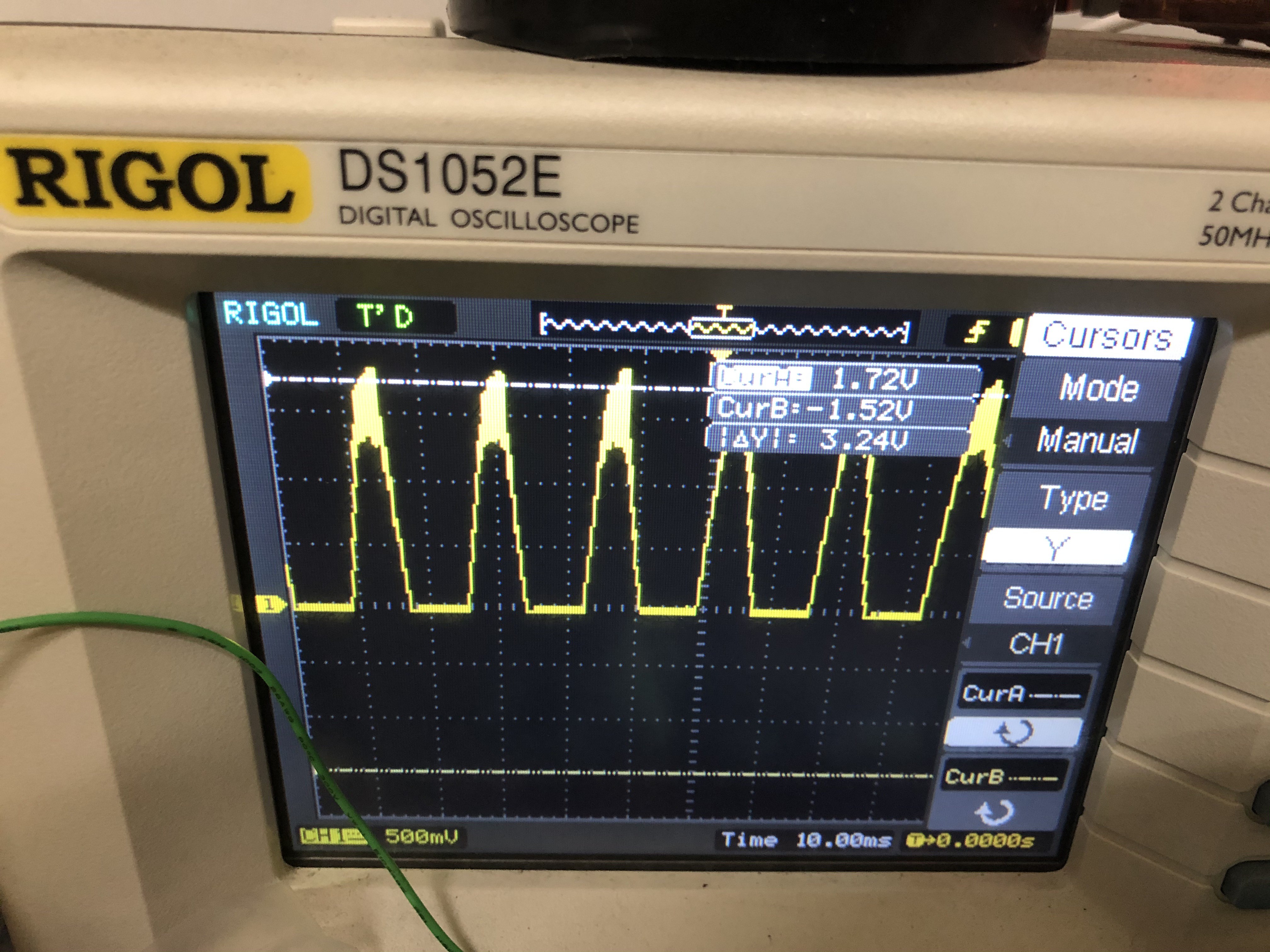
That's a little noisy, but the peaks look consistent enough that merely getting a peak reading and scaling the result to infer the RMS voltage should work just fine.
The design starts with an isolated 5V DC-DC converter. This is powered on the primary side by the 5v supply that powers the whole system. The secondary side has the negative pole tied to the neutral AC input (for L2 systems, this won't actually be neutral, but that doesn't matter. For our purposes here, it'll be regarded as the circuit ground). The hot AC input goes through an S1M diode to isolate just the positive going half-cycle. That then feeds into a voltage divider made with a 510kΩ flame-proof resistor and a 6.8kΩ one. The values chosen insure that the current through the divider results in less than 1/8W, and a nominal output of about 4.5V for a peak DC input voltage of 340V (which is the peak for 240 VAC RMS).
The output of the voltage divider feeds the input to the isolator circuit. The input and output impedance resistors are set to 75kΩ, as the arithmetic says this should result in a peak LED current of around 15 mA or so. The transfer current through the primary side phototransistor provides feedback to the input amp which sets the LED current. The secondary side phototransistor sends the same current to the output buffer. Because the whole idea is that the two phototransistors are very closely matched, the output should very closely mirror the input regardless of any non-linearities in either the LED or the phototransistors (this includes any temperature related effects).
Discussions
Become a Hackaday.io Member
Create an account to leave a comment. Already have an account? Log In.