 Maciej Witkowiak
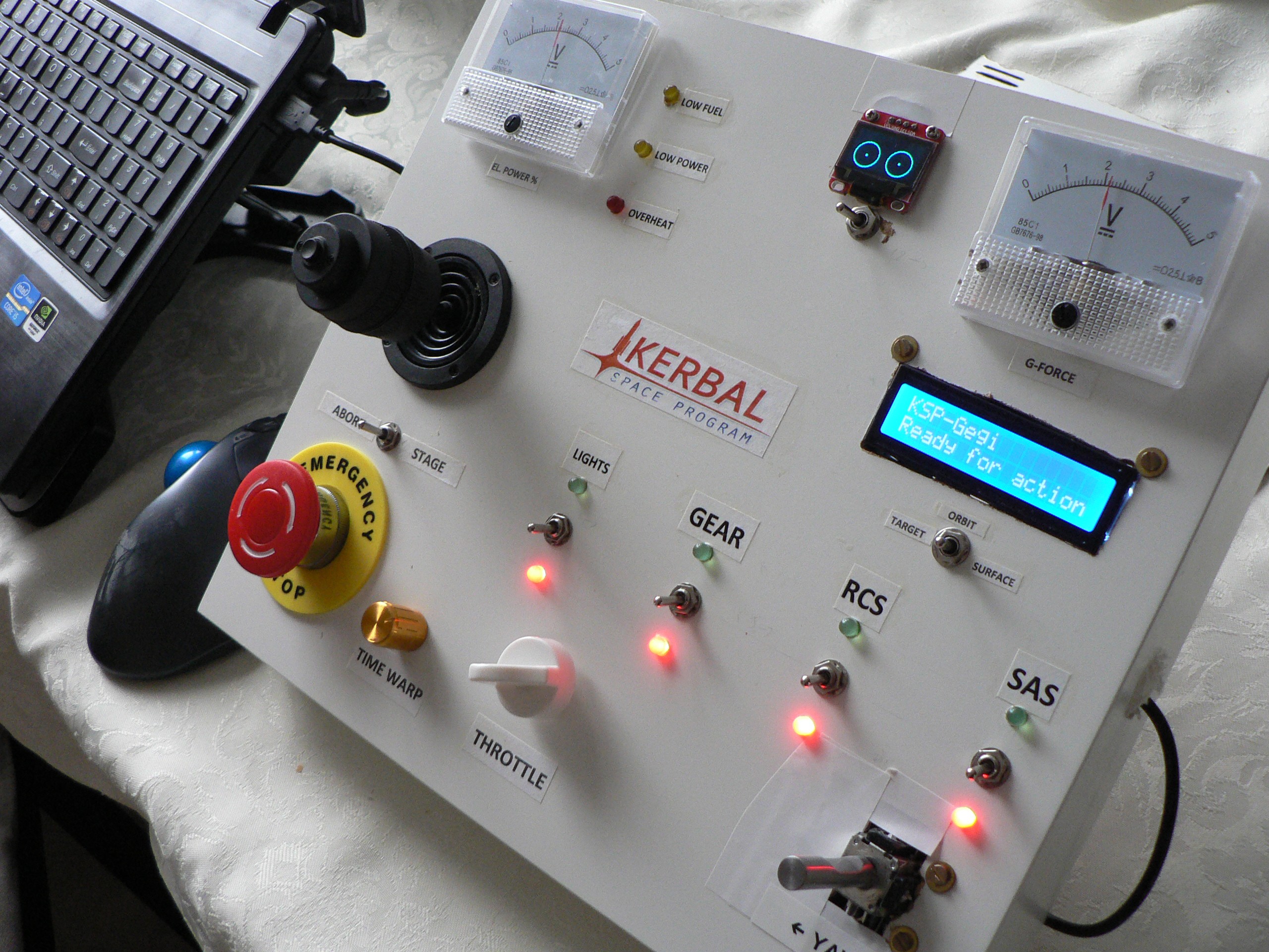
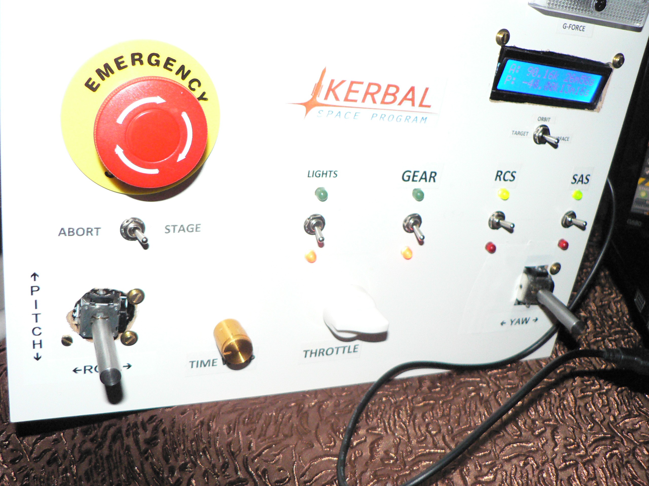
The goal is to build a rocket control panel with LED indicators, switches, pushbuttons, and more to make Kerbal Space Program game even more immersive.
Having another display makes it easier to control rockets because some of the information is presented off-screen. Also, it's fun.
The interface to KSP game is provided by kRPC module through a Python script.
The physical interface is provided by Arduino Mini Pro (driving LEDs and reading switches) and Arduino Micro Pro (providing USB serial port for control from within Python and joystick HID emulation).
The enclosure was done out of white IKEA LACK shelf.
"Gegi" [gheghi] is how my 3-year old son calls Kerbals.

 Abraham Limpo
 lpaseen
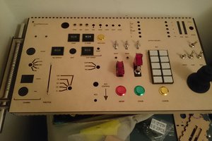
 Matthew Peverill
 daniel.bryand
Add more booster button needed!