 Eric Hertz
If you look through my projects you'll probably see that I've got a lot of *plans* for CNC systems, but nothing actually built, yet...
There's:
- #CD/DVD mechanisms and cartesian thinggie[s?]
- #2.5-3D thing
- ... huh, I thought there were more...
- Well, there's the hanging pen-plotter system I made years ago from legos...
- Oh yeah, there's the groovy microscope-slide mechanism I meant to automate...
- There's also several systems I've written software for, but were *built* by/for others.
It's time for me to build my own CNC system, dagnabbit!
A couple months back I got completely fixated on it and assembled the first axis from stuff sitting in my stockpiles.
The first necessity: a "drill-press." Those rails are 1/2in in diameter, so I needed to drill 1/2in holes in the particleboard end-plates. Doing it with a hand-held drill would be difficult. Drilling both plates at the same time would assure the holes' alignment, so the rails would be parallel, but drilling perfectly vertically would require a jig, what better jig than a drill-press? Additionally, my hand-held drills don't have chucks large enough for a 1/2in drill bit, so...
#rotary-tool-drill-press to Drill-Press conversion
Back to the first axis of this "Big Ol' CNC":
The "carriage" is from an old dot-matrix printer. It came with its own leadscrew, but it was something like 1in per turn, much too high for my intentions. It also came with rails, but I have no idea where they wound-up. The black rails are nothing more than pipe... not sure where they came from. They are a little bit tight and you can feel differing amounts of drag at different positions, but it seems OK, for a first-go.
The leadscrew is just a piece of threaded-rod I had laying around that was about the right length. I think it's 10-32. It's a little short, so I found a metal stand-off that was long enough but 6/32, so drilled it out and rethreaded it. Then I butted the threaded-rod against a long bolt of the same threading.
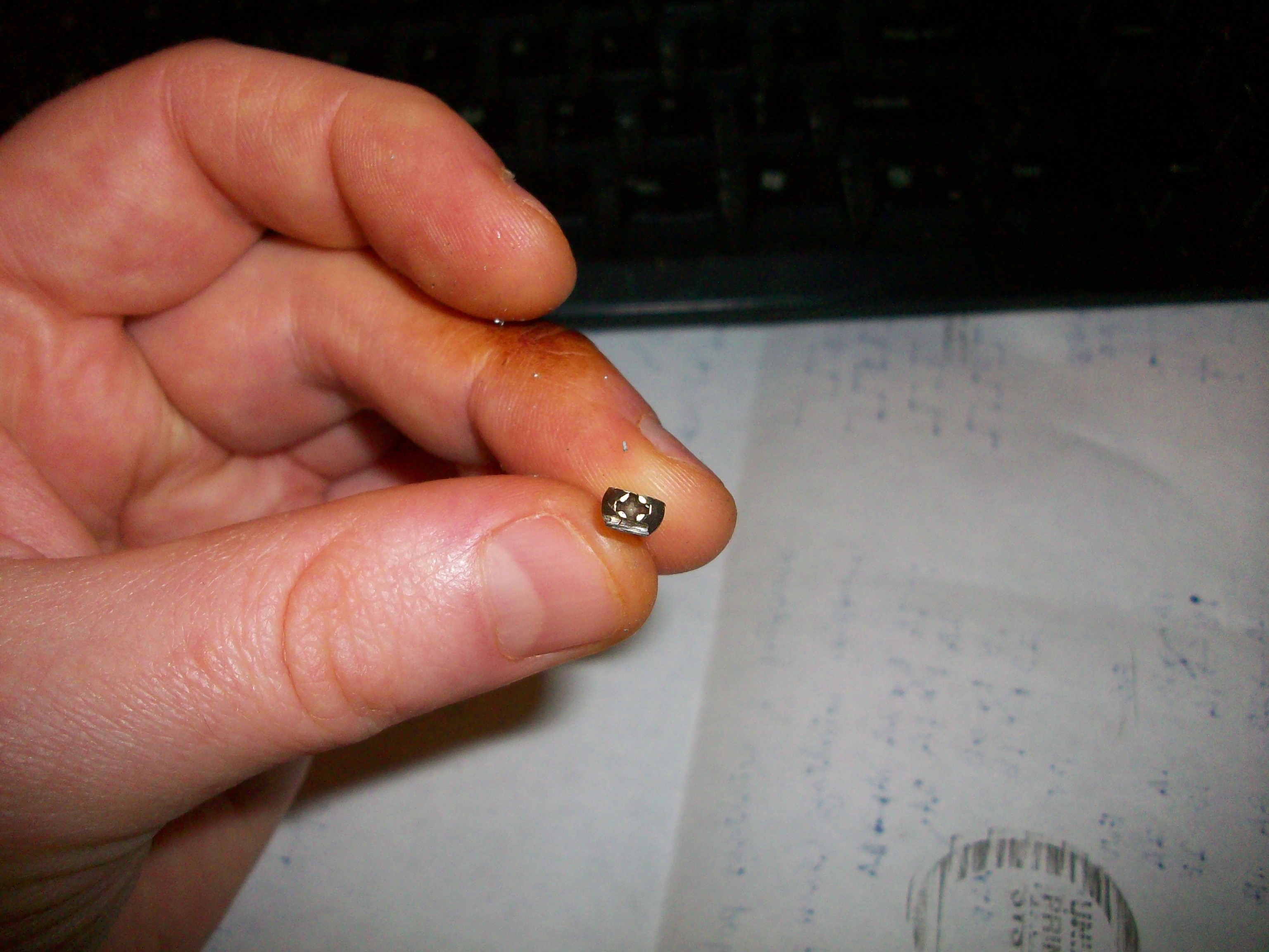
Below is the home-made tap, from a bolt, a little filing while spinning in a drill, and a cut-off-wheel.
(TODO: Better notes on making a tap! Or just link to the part in the drill-press conversion project).
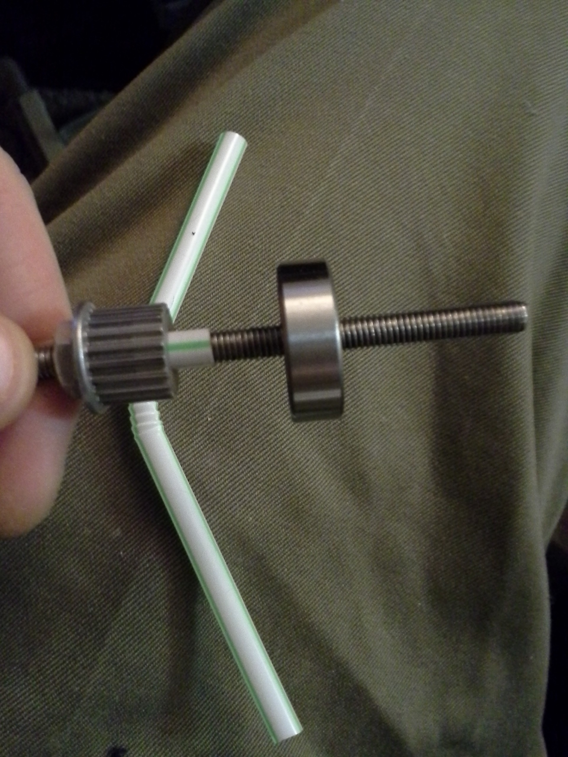
The bearings at either end (not visible in the first picture) are much too large inner-diameter for the threaded-rod, but I just happened to luck-out that some of the nuts in my possession had rounded edges, so when tightened against the bearing cause the rod to center darn-near perfectly. Two nuts on either side lock them in place.
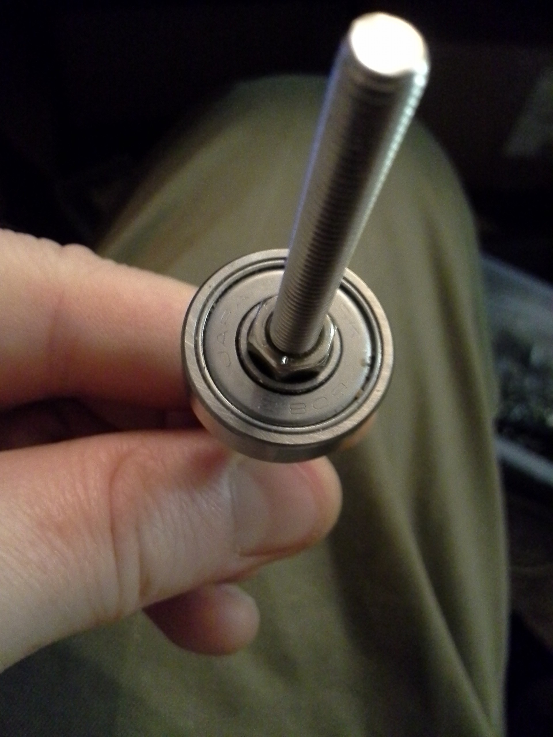
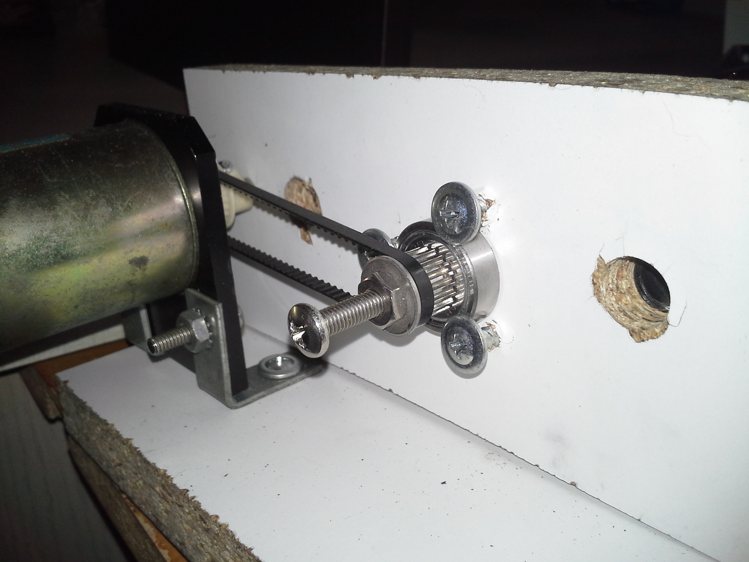
The bearing on the motor-end is held in place with three large-headed screws. The bearing on the "knob" end is held in place merely by friction and tension (wow!).
You can also see, quite clearly in this photo, just how accurately my electric saw cuts... Believe it or not, I mounted (and followed) a guide to cut a straight line, the blade managed to wander despite the guide. Wee! I've tried several attempts, several techniques... I'm pretty sure it's play in the saw. But it's good 'nough, eh?
-----------------
In the first picture you can see foam-core board at either end of the axis. (Thanks #Travelling Hacker Box! I never guessed how handy this stuff'd be!). I used it to find the center of the threaded-rod, once mounted in the carriage. I unscrewed the threaded-rod until it *just* protruded from the carriage, then slammed the carriage against the end-plate/foam-core. This put a nice divot in the foam-core. Then I poked through that with a pen-tip or something, and used that hole and the foam-core as a temporary bracket to hold the threaded-rod in position on both sides as I positioned the bearings, tightened nuts, etc.
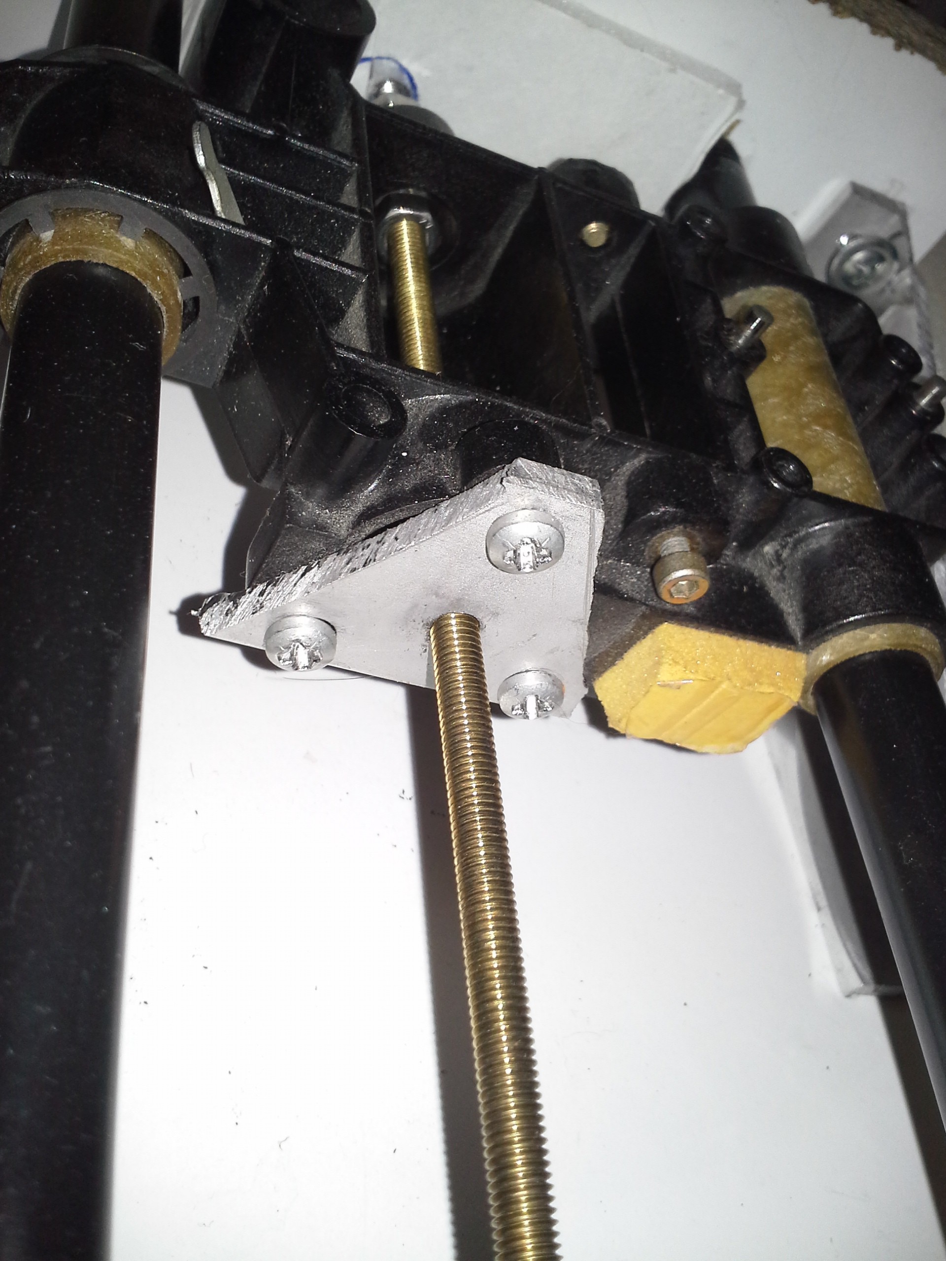
The threaded-rod is attached to the carriage via a plate I made by hacksawing a triangular piece of aluminum from an old hard drive. I drilled three holes at the corners for mounting to the carriage and a fourth near the center for the threaded-rod. My drill-press does a pretty good vertical drill, but the vice I mounted the plate in was a bit off, so the holes were slightly angled... This worked to my benefit. Originally I'd intended to use *two* of these plates, with a fixed distance between them to provide backlash reduction. (I did actually *make* two...) But, since the hole is slightly angled, backlash is almost nil just by tightening the plate perpendicular to the rod. (Handy! Now that I know about this, if I'da tapped those holes perpendicular, the alternative would be to add a washer between the plate and the carriage on one or two of its mounting holes, and tighten the third without a washer...)
I didn't have the right-sized [right] angle-brackets, but a moment of inspiration had me hacksawing old hard drives again... The right-angles are darn-near perfect, but the end-surfaces are actually slightly angled (by manufacturer-design). That's fine, a little bit harder to align perfectly, but not bad. I drilled and tapped (with my homemade tap) 4 holes in some of the thickest parts of the aluminum in each bracket... And was pleasantly surprised at how well my hand-made tap held up.
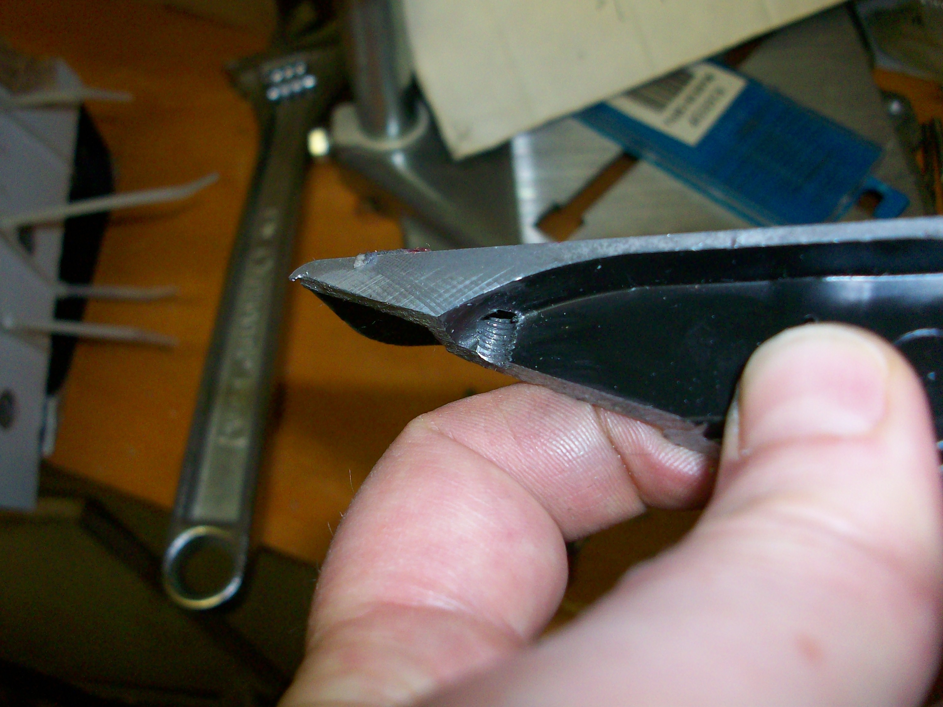
(Note: Slice the sides of the bolt's head off with a rotary-tool cut-off-wheel, then use a crescent wrench rather than trying to use a screw-driver for tapping! Save yourself some bloody knuckles!)
Between the threading on the pipe rails, the tension on the threaded rod, and maybe a little bit of magic, the end-plates don't even have to be screwed-down to the angle-brackets. Good, I was getting impatient at that point, anyhow... trying to figure out how to measure those holes for the endplates. I did end up sticking a small screw through the backside of one just to prevent slippage.
The belt-sprocket was removed from a stepper-motor. (How did I remove that thing...? It must've involved a hammer, but what did I slip inbetween the motor and the sprocket?). The stepper's shaft was *slightly* larger than the threaded-rod... The wobble was *barely* noticeable, and probably not a problem, but I did eventually add a "shim" of sorts... That's a pretty tight fit, it had to be screwed on. Just luck, again, that the straw was darn-near exactly the right size for the job! Though, I suppose something like heatshrink could do a similar job.
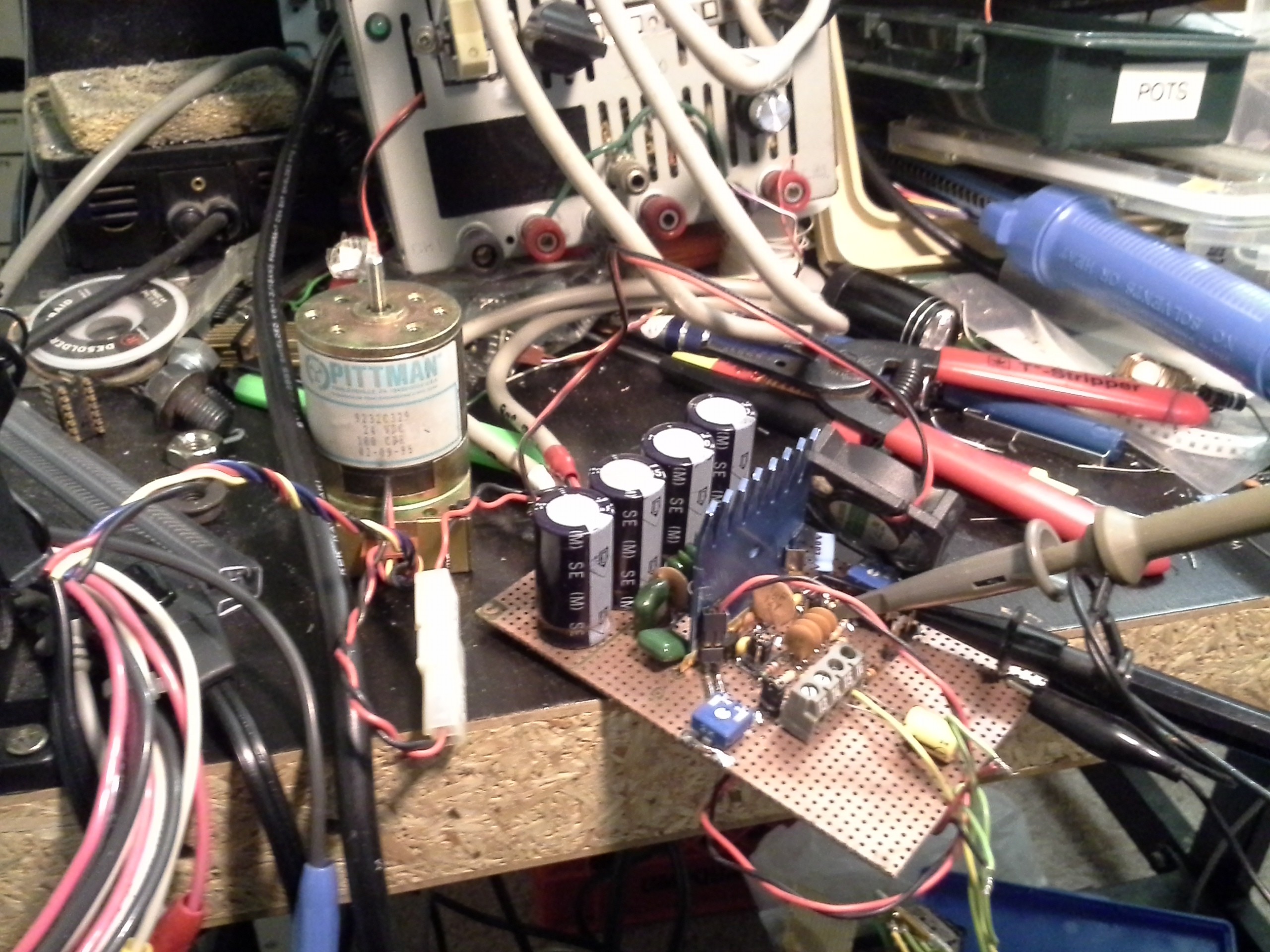
Here it is under-test in my new newly-remodelled wood/metal shop... yahknow, from that old "spare-room" once called the kitchen.

The motor is quite old... I think it's marked 1980-something... The encoder-disk is great, it's a big-ol slab of circular plastic with big-ol notches, there can't be much more than 100... But: 10/32 threaded-rod means 32 turns per inch, means 3200 notches pass by the detector per inch of travel. Also, when using quadrature there are 4 detectable positions per notch, so that should be a resolution of 3200*4.... 12800 detectable positions per inch?! I think that'll be fine.
I am direct-driving this, the only "gear-reduction" is from the threaded-rod itself. Thus, the motor is pushing a bit of a load (remember I said how tight the carriage is on the rails? *that* tight). But at 12V it travels end-to-end in about 5 seconds, and draws something like 1A... (5V is *just barely* too low to overcome static friction). It's rated for 24V, so I think it'll be OK.
----------
Now, onto electronics!
(Kinda wish I'd taken more pictures of the hardware-build! What about those friggin' triangular plates?! TODO)
I've a few different motor-drivers to choose from...
For #The Square Inch Project I worked on an all-in-one 3-axis controller... #Motorator - Self-Replicating PCB router board. This would contain a PIC32 (they seem to be my new Go-To these days), and enough H-bridges for three motors... I got a bit side-tracked trying to kill two birds with one stone, or something, so couldn't figure out whether I was designing a board for DC motors and encoders, or for bipolar stepper motors (e.g. for a CD/DVD carriage-based system). (In reality, why not design *both*?).
I also got a bit sidetracked trying to use some surface-mount dual H-bridge chips... They're rated for 750mA, and probably designed with bipolar steppers in mind... But I had some crazy idea maybe I could make them work with this axis... The crazy-logic that took a couple days' experimentation was something like "well, if I can't run 'em at greater than .75A, I'll just pump up the voltage!" Yeah, so... Now I'm pretty sure, but not certain, that logic works great for stepper-motors but not-so-much for DC motors.
Quickly glancing at those logs, just now, I completely forgot about *this* potential design...
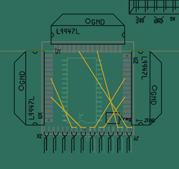
The L9947's are probably what I'll go with for this project... Technically, each chip can drive up to three motors (one at a time), but only one motor can be driven up to 3A, the others up to 0.5A... 3A should do for this axis. Not sure if I'll keep this layout, now that 1sq in is no longer a requirement... But there are some ideas in there that might be handy... They're technically through-hole components with staggered-leads in two rows, but I don't see why they couldn't be surface-mounted on an edge, as shown... I kinda dig it, but routing power and other fat traces might be a concern... TBD.
Anyways, I'll probably just wire it up point-to-point for now.
Another thing about the L9947's is that they're really unusual, in my experience, in that they have a *bus* interface... 4-bit data-bus with read/write signals and a strobe... not unlike a 4-bit SRAM or EEPROM interface, or maybe one of those ASCII-LCDs. Also, it's not exactly designed for high-speed switching. Yeah, that all makes things like PWM a bit difficult, but not impossible... I did quite a bit of experimenting with this in another project's logs... (was it the 2.5D/3D thing?).
Then... There's the latest "procrastination," I guess... For some reason I got fixated on trying to use an audio amplifier chip to drive my DC motors. It's been a running curiosity for some time, and now seemed as good a time as any to give it a whirl. The Class-D audio-amps I've got are TDA7490's and are rated for 4A... Also they work at ~200kHz PWM, so that was another perk (compared to the "difficult-pseudo-PWM" required by the L9947s). Several days (weeks?) later, and I think it's time to declare that endeavor "not-suitable" even for a hacked-together project like this, made of stuff I have on hand. Those experiments are under #Random Ridiculosities and Experiments).
I *might* be able to get it to work reliably, and I'm not at all opposed to having three different axes driven with entirely different one-off circuits. Actually, I kinda like that idea. But for now this system just isn't reliable enough, and for now trying to fix that just isn't in me. On the plus-side, I etched my first PCB in nearly a decade(?!) and found it to be quite a bit less difficult than I remembered and learned a few new tricks in the process.
It's time to get this dang axis running!
-----------
As far as future-plans...
My second-axis is pretty well laid-out. I've got most of the parts sitting on the table waiting to be assembled. This axis will be based on the same style "pipe" (but longer sections). It just happens to be that a couple old pen-plotters I took apart long ago had really nice (I mean *really* nice) gliders on one axis... These have linear bearings... I mean, they're *really* nice. (TODO: take some pictures!) And they also happen to be the same diameter as the pipes. Well, I'll probably have to strip off the paint, but otherwise....
I have another threaded-rod, this one I think is 1/4-20. At first I planned to do it similarly to the first, one rod. But it occurred to me that there might be some... what... lateral? play with the rails separated almost the same distance as the first axis's length. So, I thought, why not add a second threaded-rod...? The two will be linked via a timing-belt. I only had one threaded-rod at 1/4-20, but I also had a normal-ol unthreaded metal rod which seemed to work well with my 1/4-20 die. Technically, I think, it's a smaller diameter than would usually be used for 1/4-20, but it threaded smoothly and should do the job.
I haven't yet figured out *exactly* how these two axes will be attached. I think two bolts and what're those things called, they're like insert(?) nuts but have flanges that grab-hold of the wood from the backside... The idea, then, being that I could remove these two bolts quite easily. If I decide to add another piece of wood to the side of my first-axis, this mounting-method would allow for the first-axis's carriage to ride either horizontally or vertically... E.G. for a mill/router, the work-surface could be mounted atop this first-axis's carriage, and a heavy cutting-tool could be stationarily mounted to the table. OTOH, if I mount the first axis vertically, I could attach a light third-axis (e.g. a rotary-tool) to the first axis's carriage. Quick-change via two bolts.
But that's likely to be a little ways out, still.
With a single axis, I'm thinking of e.g. a drill-press with a force-feedback-system tied to the lever. This, of course, means mounting the system upright, another mounting situation I've yet to figure out.
----
Another use for this system is as the tooling-mount for a lathe. It's probably a bit oversized for anything I'll be lathing, but should probably have enough precision. I'm visualizing the lathe's chuck to be mounted such that it crosses somewhere roughly halfway through the first-axis. The first-axis's carriage would hold the tool. More quick-mount contemplations...
So, you probably get the picture that this system is usable/useful in each stage of development. Just one axis? Drill-Press. Only two axes? Laser, Lathe... Three axes and you're set!
In fact, some time has been spent thinking about ways to actually build a part to complete the system, *using* the incomplete system... E.G. for a single-axis it's not absolutely necessary to have the threaded-rod supported on both ends. In that case pushing is a bit more difficult and unpredictable than pulling. But say a part is needed to support the far-end of that rod, and that part needs to be turned on a lathe... For instance, a spacer to fit between the bearing and the threaded-rod. Well, with a drill strapped down to a table we have a one-axis lathe already. Just make sure all the heavy-cutting motions are pulled toward the knob...
Luckily, it turns out, I didn't have to do that ;)