 Eric Hertz
my old "oneAxisHolder" project was AVR-based and ran on 5V...
I hacked the encoder attached to my motor to work well at 5V by replacing some resistors with potentiometers. This encoder's circuit... well, it's *simple*; it just has two IR(?) LEDs, two photo-transistors, and four resistors.
So, when I moved to my "multiAxisHolder" which is now PIC32-based, those resistor-values didn't work at 3.6V. Well, shit, I ain't bouts to hack those resistors again, and plausibly have to do it *again* if I later decide to use it with a 5V system... so:
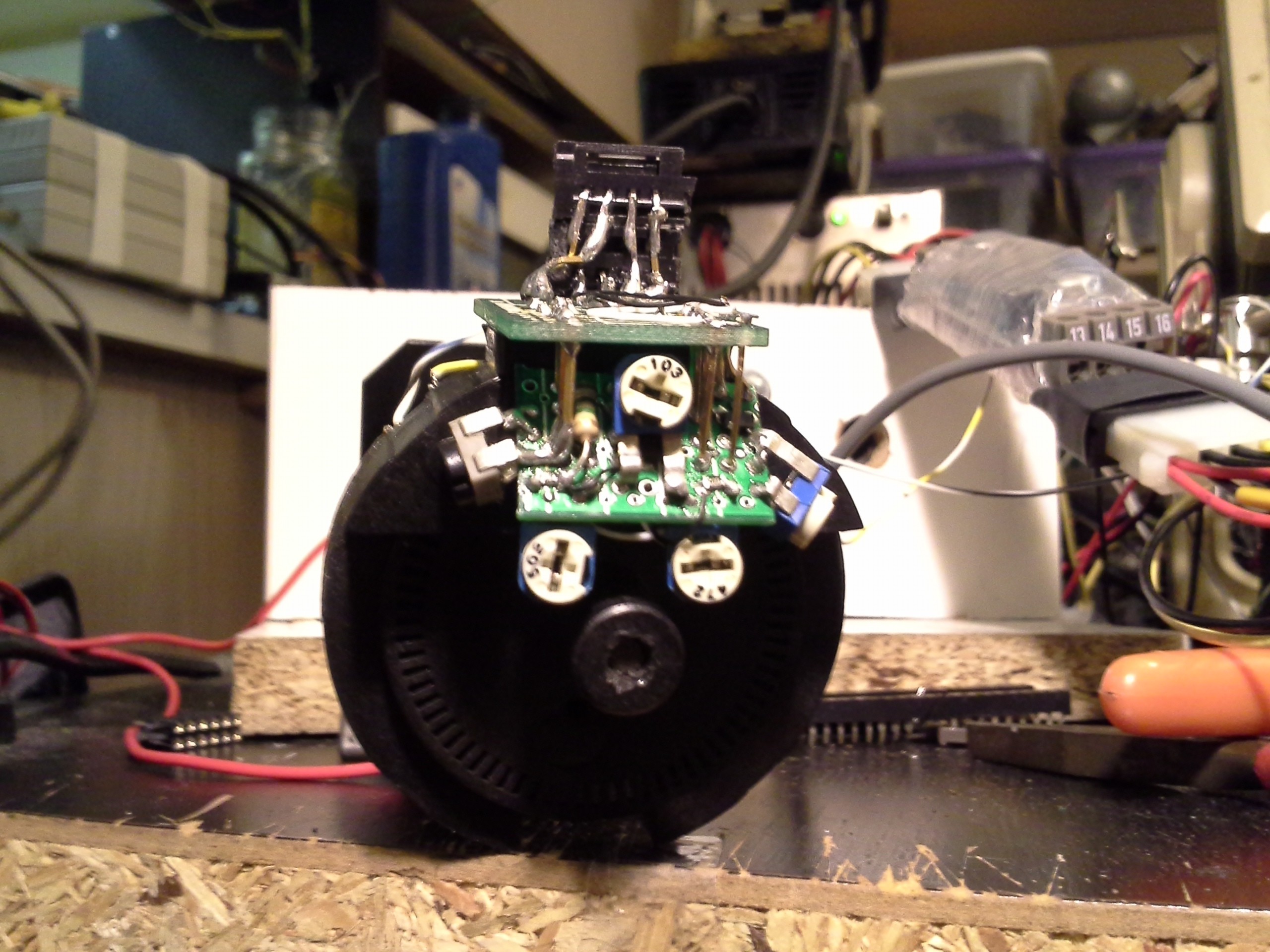
This dandy thing is soldered to the original encoder's PCB where the resistors were originally located... (plus a few extra holes I drilled in empty-space).
Stupid thing took several days to assemble, and couldn't be tested until it was completely assembled and soldered to the original board, so I was *really* cautious with every connection, and it worked right off the bat :)
It's more than just a bunch of pots. Here we have a 3.0V LDO running the LEDs and photo-transistors. Under the center pot is a comparator running off the source-voltage. The center pot sets the threshold-value for the comparators. The four remaining pots set the values for the phototransistors and LEDs.
This part's kinda funky. The original circuit had a 330ohm resistor for one LED and a 451ohm 1% resistor hacked-in for the other. It would seem these diodes have differing brightness?! Or maybe they're not perfectly-aligned or something... Anyways, it's handy having pots for all these things as I've been doing some experimenting. I'll come back to that.
The new board and potentiometers *just* fit inside the encoder's housing when assembled, which is why it's so... 3-dimensional (yes, it's mounted at about a 70degree angle). It's *cram-packed* both top and bottom.
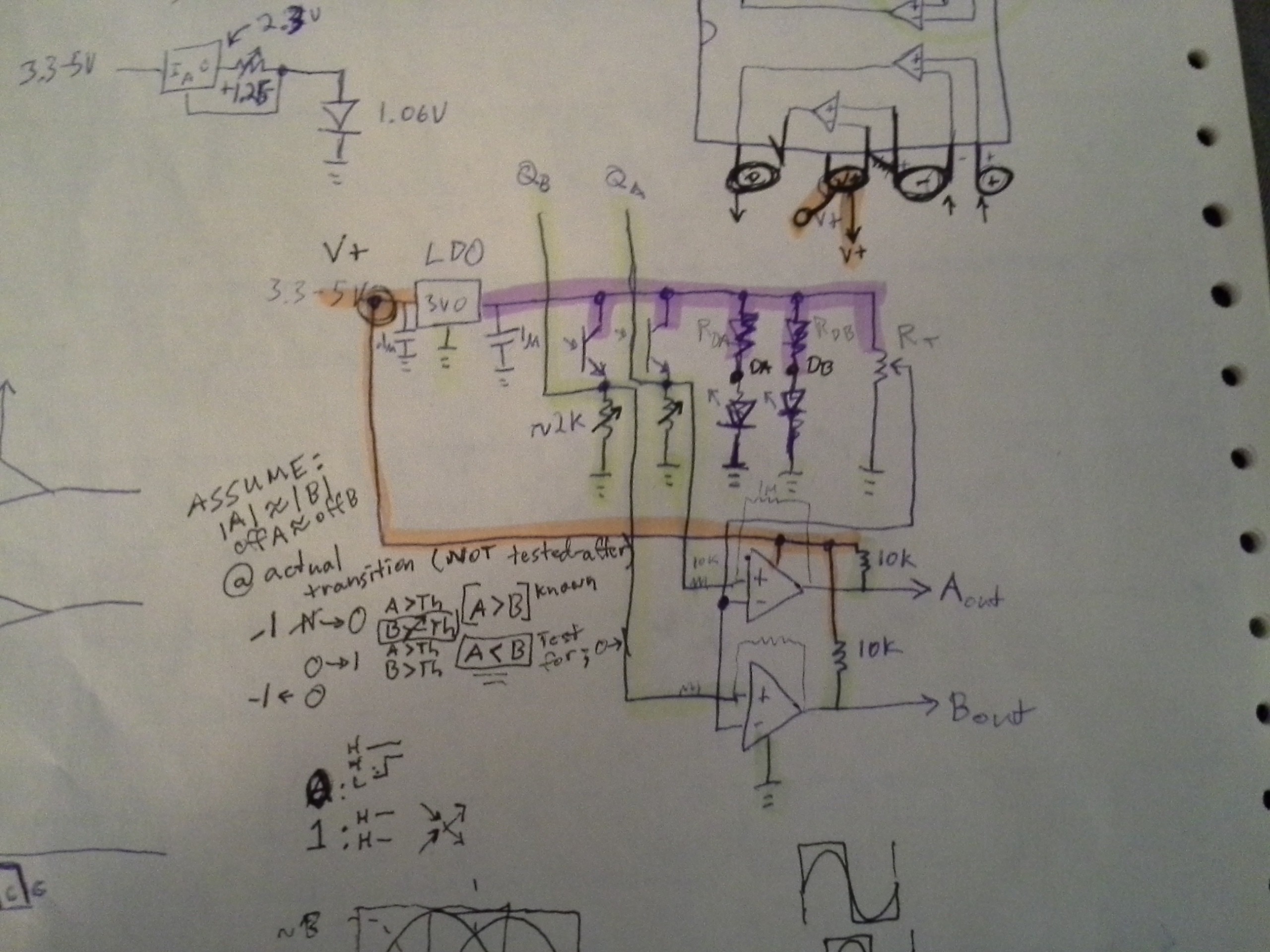
So, now, it will run off 5V down to 3.2V, give a digital output at that value, and not have to be recalibrated for a different supply-voltage.
As for experimenting...
I have some ideas about using the *analog* output from the photo-transistors as a means to increase the resolution. https://hackaday.io/project/9351/log/32010-quadrature-encoders-with-analog-output
But I haven't started coding that, and I wanted to get this thing running with my current system... So, I included connectors for both digital-output and analog-output. Also, past-experiments with ball-mouse encoders show similarly analog-output... so this should be a pretty versatile and reliable/sturdy testing system for stuff like that if I decide to feed them into, say, the microcontroller's comparator-inputs or even just the schmitt-triggered digital inputs
With careful adjustment of all four potentiometers, it's possible to get what looks almost like a perfect sine-wave from each channel, running from about 0V to about 2.5V, so... got some 'sperimentin' to do.
And, yeah, those comparators are doing their jobs quite well, system's back up and running!
Oh, yeah, I'm running the motor off an audio-amplifier IC... again for the sake of experimenting. https://hackaday.io/project/9351-blogifying-io/log/30930-currently-audio-amp-motor-driver-cnc-machine
Discussions
Become a Hackaday.io Member
Create an account to leave a comment. Already have an account? Log In.