So you've got the code and the whole build environment is set up and configured.
Hitting verify (which is really just compile without uploading) gives you a nice output showing you the memory usage of the resulting code, based upon your chip memory -
Sketch uses 309,476 bytes (71%) of program storage space. Maximum is 434,160 bytes.
Global variables use 56,616 bytes (69%) of dynamic memory, leaving 25,304 bytes for local variables. Maximum is 81,920 bytes.
If you try to upload without things connected, and without a USB to serial TTL converter (3.3v compliaint) you'll get this -
warning: espcomm_sync failed
error: espcomm_open failed
So now is time to put everything together. Below is a pic of the wiring for an ESP07 module. Be wary, this is from the underside, so you'll need to carefully mirror every pin horizontally when flipped over.
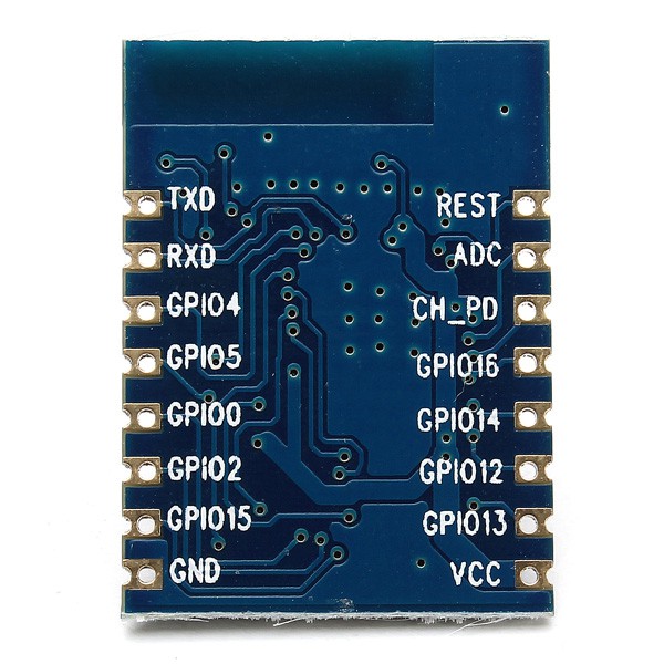
For your particular variant, this arrangement of pins will vary wildly. I think you can complete this project with one of the ESP-01 modules, as all we need are -
- VCC
- GND
- TXD
- RXD
- REST
- GPIO2
- GPIO0
- GPIO15
Strictly speaking, GPIO15 is tied to ground on the ESP-01 so all is good here, and the REST pin is tied high to +3.3v I think (thru a resistor?).
I found a great resource online showing that the boot mode of the ESP is actually controlled with three GPIO pins -
| GPIO0 | GPIO2 | GPIO15 | |
| UART Reflash mode | 0 | 1 | 0 |
| Start running from flash | 1 | 1 | 0 |
| SD Card Boot | 0 | 0 | 1 |
This says it all, if you're reflashing your ESP, you should tie GPIO0 to ground, and tie GPIO2 to +3.3v. I think I just tied GPIO15 to ground. For my strip perfboard, I wired up an SPDT switch to GND, GPIO0, and +3.3v respectively, so as to control the boot mode, and allow reflashing even when installed in the hat.
You'll now need the USB to TTL Serial converter dongle. I had a nice 3.3v compliant model.
You should connect up like so -
| USB To TTL Serial Converter | ESP8266 (ESP-07) |
| TXD | RXD |
| RXD | TXD |
| GND | GND |
Just tell the Arduino dev environment which COM port your USB to Serial Converter is on, and it should work. You'll see a series of dots appear as it is uploading. Mine filled up one and two third rows with dots before it was finished.
The program will begin running immediately, but because the data output to the LEDs is on the RXD pin (it uses CNLOHR's I2S implementation, which uses this pin), it won't be going anywhere until you wire it up to your LED strips, and give them some power.
This does have the effect that the TXD pin on the ESP is still available, hence the Serial Monitor in the IDE environment can update you with debug info if required, even with the LEDs connected - as you can see my code is dotted with serial debug texts.
Although you've just seen your code run quite nicely if you wire in the WS2812s, if you power cycle the device, it'll not do anything because it's still in bootloader mode. Just flip the switch to run the code.
This is really all there is to it - that's why I love developing for the ESP8266, due to all the hard work building an Espressif native dev environment in Linux is now unnecessary, it opens the door to really rapid development from a Windows box (or Mac?).
Discussions
Become a Hackaday.io Member
Create an account to leave a comment. Already have an account? Log In.