GE discontinued the famous G35 hacker friendly addressable RGB led Christmas lights. After buying 7 different brands I found one at Home Depot that was easily reversed. I planned to run it off of an esp8266, nodemcu wasn't fast enough so it is run off an arduino. The code mainly uses bit shifting and direct port manipulation. I may migrate the code to baremetal atmega328 , but thats when I need the space. At that point it may be a baremetal esp8266.
The code runs currently and changes the lights. They function as shift registers. Each led consumes the last 24 bits of the data for color intensity. Each led has a single byte for R G and B channels. The data has the clock and data combine into one data line. It is in a high z state when no data is sent. It is pulled low as a 0 and pulled high as a 1. The lows seem to effectively make a clock signal.
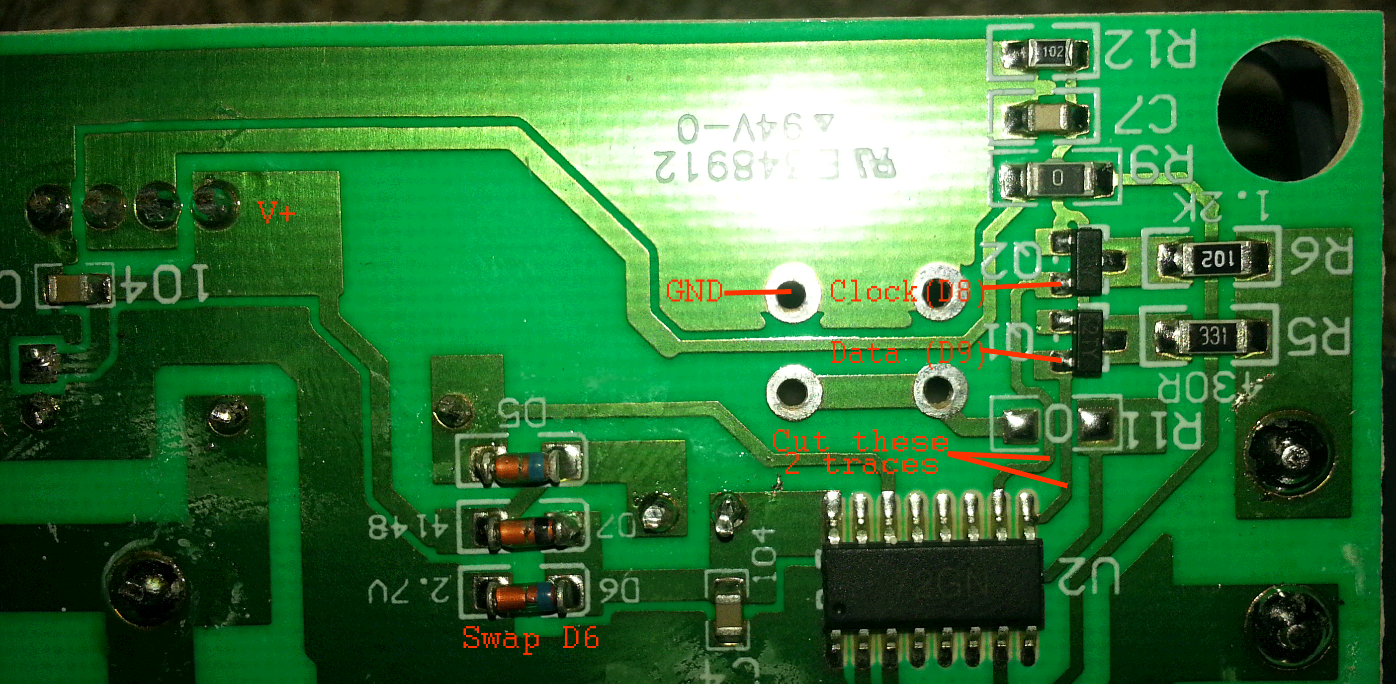
The issue is that the driving controller in the device runs at ~103.6 volts as positive and ~100 volts as negative. This controller drives two transistors in an odd manner. The wiring is basically cutting the traces to the two transistors, connecting the one labeled Q1 to pin 9 and Q2 to pin 8. The power is then using the same power as the main IC. The lights must not be plugged in when programming or you might end up with a usb cable welded into the port. Line voltage is something to take seriously. I have been using a USB isolator to program it while connected. The eventual goal, after the code is finished, is to use optoisolators on the serial line to isolate the mains voltages. This output/input will be the only external connector on the control box.
The original data was changing between 4, 5 and 6 bit frames. After realizing that each bulb's color was 8 bits I attempted 8 bit frames and it worked. When measuring the data, each data bit is 2us, each rest between bits is 10us and each rest between frames is 25us. it also has 4ms between each data packet. The LEDs don't seem to particular about timing. They are very forgiving. I have not tested the tolerances of their function, but I have added a lot of coding delay at points and they still worked.
The code currently takes in serial commands and modifies an array of values. This seems to be the easiest method longterm. It is fully working, but could use some optimization.
ToDo:
ESP8266 web interface
Eeprom saving so it can start in the last state
Patterns such as chase and fade
Triac for switching female outlet on end
Compatibility with included remote
 Tryst
Tryst
 Yann Guidon / YGDES
 Ron O'Sullivan
Just hit Lowe's and Target on 12/26/2017 and found the same lights under different names. Lowe's had them as "Holiday Brilliant 10 Color Changing 25 C9 LED". Target has the as "Philips Pick-a-Color C9". The Philips are about 2x the cost of the Holiday Brilliant. They are the exact same lights with 25 lights and the 5 lines (3 for V+, V-, Data, and 2 passthru 120VAC) coming out of the controller. The only read difference was the Philips had a more "modern" looking RF remote.