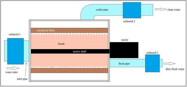
Close
0%
0%

Automatic Self Cleaning Filter (Liquid)

Low Cost & Automated,using Atmega328P (Arduino) as it's brain.
Controls Solenoid valve and DC Motor, by monitoring pressure inside.

Similar projects worth following
Filters are an essential part of any industry, I mean, you can find them everywhere, in Automotive, Aerospace, textiles, beverages ,food, paper, pharmaceuticals, you name it.
You can find filters for any type of fluids / liquids, any size. They help you remove contaminants and other materials.

Well, You can find many industrial grade, sophisticated filtering systems available in the market. Me and my friend Tushar decided to build one, Low cost and Automatic.

As an electronics engineer, I jump on designing electronics for the system, and mechanical part to the Tushar, who is of-course a Mechanical engineer.

FYI, This system isn't limited to the industry only, one can use it for in-house filtering.

Typical System Diagram

Construction:

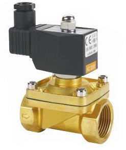
  • As shown in Image Solenoid valve 1 will be connected to the INLET of the filter.
  • Valve 2 is connected to the OUTPUT side as shown in figure.
  • Valve 3 is to flush out all the dirt/contaminates.
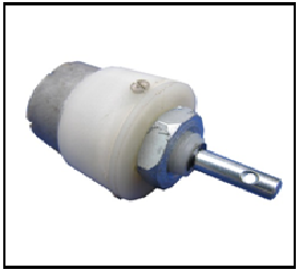
  • A cleaning element (a brush) that is covering the whole length of the filter will be connected to a DC motor.
  • Two pressure sensors installed on INLET and OUTLET side of the filter will continuously monitor pressure inside the filter chamber.
  • Output of these two pressure sensor is given to the Microcontroller (In this case, to the Atmega328P) through signal conditioning.
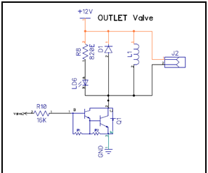
  • On defined pressure difference condition, Microcontroller will turn ON, DC motor and solenoid valves.
  • Note: Initially, Instead of pressure sensor we are going to demonstrate the system by using LDR, in which by varying resistance of LDR will correspond to pressure sensor.

Working:

  • The liquid or water flowing from the filter will clog the filter eventually, due to contaminants / dirt, which will lead to pressure difference.
  • At some point, where OUTLET pressure is higher than the INLET side.
  • When a preset value of pressure difference is reached the microcontroller will start the cleaning cycle.
  • During cleaning the output side valve will close and the flush line valve will open, simultaneously the motor will start rotating the brush thereby cleaning the filter from inside.
  • The water flowing from input will carry the dirt along with it into the flush line.
  • After running this cycle for preset time the regular flow will be started with water flowing from a clean filter.

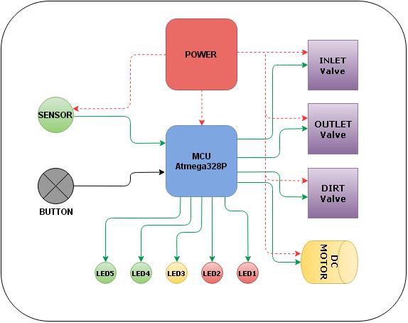
Requirements for the projects are pretty straight-forward.

  • Continuously Monitor Sensors.
  • Control the Solenoid Valves [INLET,OUTLET & DIRT Flush].
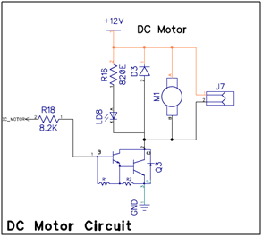
  • Control the DC Motor.
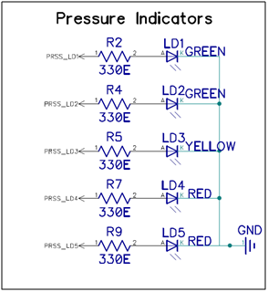
  • Pressure indicator LEDs.
  • Button to Manually Clean the chamber.
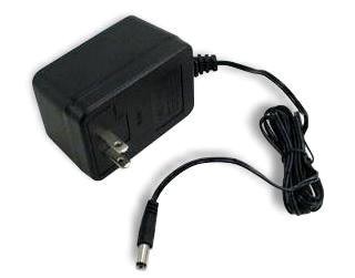
  • And of-course Power Supply, with enough current rating to drive the Solenoid Valves and DC Motor.

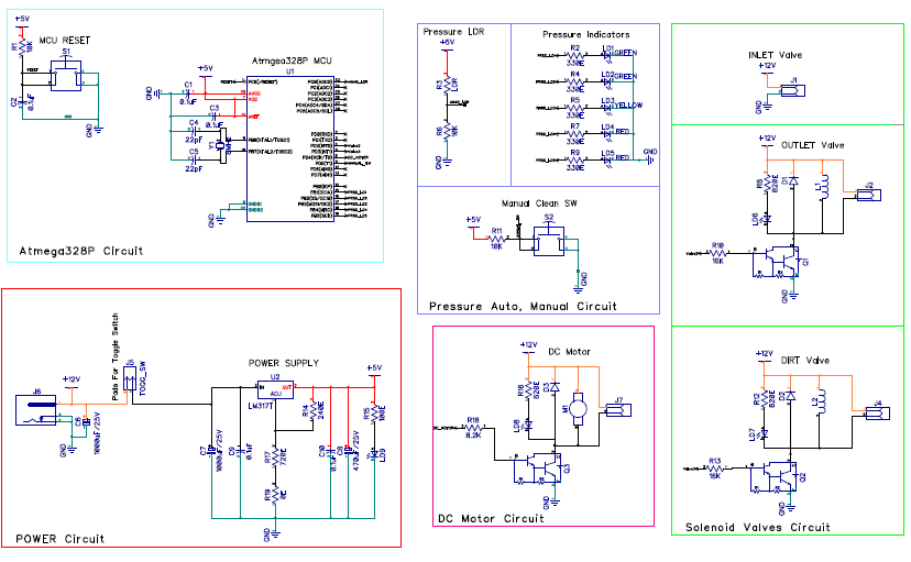
Block Diagram: Electronics Control Unit:
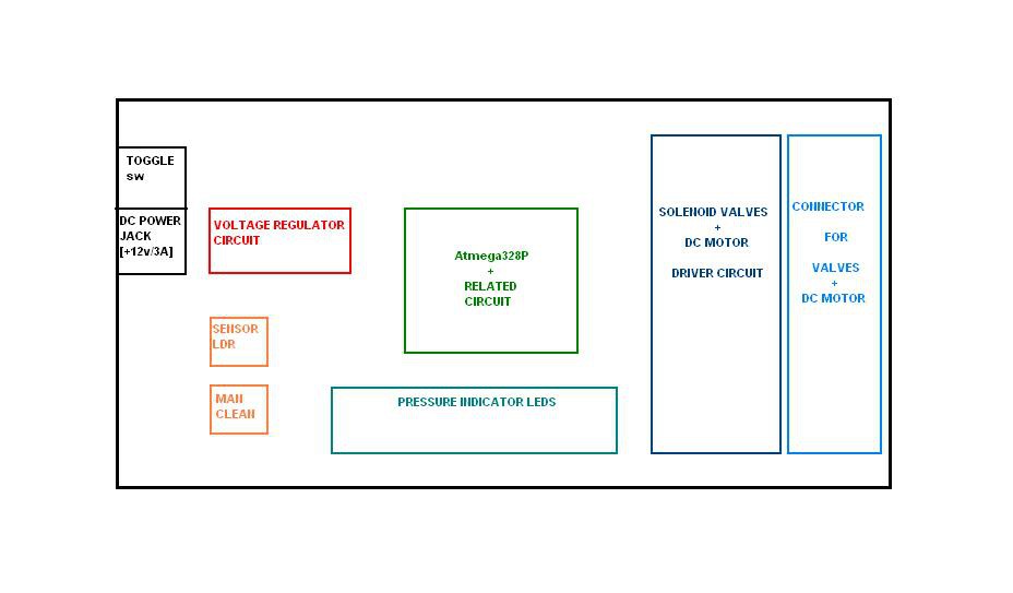
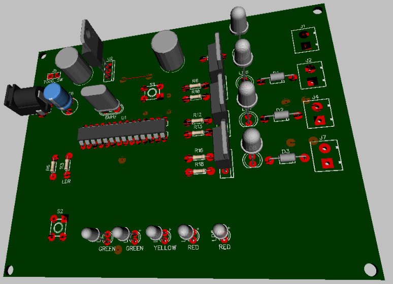
Hardware Look-Up:

ComponentQuantityPower Rating
Solenoid Valve (8 mBar)3+12V / 5Watts.
DC Motor (30 RPM)1+12V / 400mA
LEDs (3 mm)55V / 20mA

Working - System level

System works in two modes.
  • Idle Mode
  • Clean Mode
  • Idle mode operation, that is when pressure inside the chamber is below threshold value, system functions normally such a that.
    • INLET Valve = ON
    • OUTLET Valve = ON
    • DIRT flush Valve = OFF
    • DC Motor = OFF
  • Clean mode gets activated when the pressure inside the chamber passes over threshold value, in which case system function as below.
    • INLET Valve = ON
    • OUTLET Valve = OFF
    • DIRT Flush Valve = ON
    • DC Motor = ON
  • System stays in the Clean mode, until the pressure inside the chamber drops below the threshold level, then re-enters into the Idle mode.

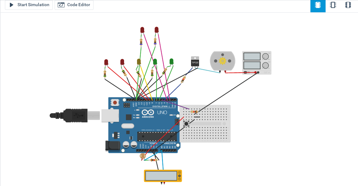
Working - Bits and Bytes level:

  • LDR used to simulate pressure sensor, changes resistance, depending upon amount of light falling on it.
  • LDR is connected to one of the ADC analog pins of MCU, where MCU carry out the Analog - digital conversion.
  • Five LEDs are used for visualization purpose, indicating current pressure level inside.
  • Button is provided to manually clean the filter. On Button press, systems goes into the Clean Mode.

NOTE:

This Project Will have Two Stages,

Stage 1 - We are using Light Dependent Resistor.

Stage 2 - We are going to use Actual pressure sensors.

As stated above, To carry-out demonstration of the system, We are using LDR as to simulate the pressure sensor.

So, High Pressure resistance = LDR Dark Resistance.

V1_07_Project Filter.pdf

Full Schematics

Adobe Portable Document Format - 67.87 kB - 02/03/2016 at 11:23

Preview
Download

  • 1 × DC Motor
  • 3 × TIP122 Discrete Semiconductors / Power Transistors and MOSFETs
  • 9 × LEDs Electronic Components / Misc. Electronic Components
  • 2 × Tactile Switch
  • 1 × Toggle Switch

View all 11 components

  • Testing

    Amar Potdar03/13/2016 at 12:15 0 comments

    Ok here is the video of system under testing.

    I kept it running for 24Hrs. Testing thoroughly is the best thing,

  • Hardware - PCB Design

    Amar Potdar02/24/2016 at 19:43 0 comments

    Diptrace is really a best tool for Schematics and PCB designing. I really recommend you to use it.

    Once schematics is drafted and tested (using 123Dcircuits), it was quit easy to design the PCB.

    I pre-decided about the placement of the components, by considering ease of use, ease of routing, minimum noise.

    Hardware Placement

    PCB will be Single Layer & Homemade, baked at college lab.

    PCB design with DipTrace isn't a tough task.

    Following are the images, to walk you through.

    Top View

    PCB 3D View

    Home baked PCB etching.

    - Single Layer

    - etched using Layout photo print + Iron + Copper Clad + PCB etchantFeCl3

    Home baked Single Layer PCB

  • System Simulation - 123D Circuits

    Amar Potdar02/03/2016 at 12:04 0 comments

    Self Cleaning Filter - 123D Circuits

    While this project, I came across cool website https://123d.circuits.io/.

    Honestly You no longer need Hardware to Master Hardware. It's complete package for design and development of circuits.

    Schematics, Coding, Simulation and PCB Design Everything on a single place. You should try that out. Super Cool!!

  • Hardware - Schematics

    Amar Potdar02/03/2016 at 11:22 0 comments

    Well, After carrying out all the necessary calculations to choose right component, it's time to design schematics.

    I decided to use Diptrace, to Draw Schematics and PCB.

    I really love this CAD tool, It won't take much time to learn this tool. And it is full of some cool features. Am planning on to write a blog about this.

    In Last log, I discussed about driving and power supply circuits. There isn't much to mention about MCU and circuit around.

    Atmega328P (DIP) running on 16MHz Xtal and Reset button, thats all.

    - INLET Valve is always going to stay on, in Idle & Clean Modes.

    - So I have not used special driver circuit (Running directly on +12V Power Supply), for INLET valve.

    - Terminal Block Connector are provided for connecting Solenoid Valves and DC Motors over long wires.

    Download Schematics.

  • Firmware - pseudo Code

    Amar Potdar02/03/2016 at 09:33 0 comments

    As stated earlier in Details, System will operate in Two Modes, Idle Mode and Clean Mode.

    This system is a better example of Real-time parameter monitoring and control.

    In Real-time monitoring, Continuously monitoring the sensor value, and comparing it with the specified value. Depending upon the current sensor value, System goes either into Idle or Clean Mode. Also, Manual button is provided to manually clean the system, On pressing the button system goes into Clean Mode.

    In control, We are switching ON/OFF Solenoid Valves, DC Motor and couple of LEDs.

    Pressure Indicator LEDs:

    For Controlling, Operating modes and pressure indicator LEDs, I have decided to take state-machine based approach.

    There are total 5 LEDs( 3mm - GREEN, YELLOW, RED) are used

    GREEN = Low Pressure.

    YELLOW = Medium Pressure.

    RED = High Pressure.

    pseudo code:

    //----------Variable deceleration----------

    Valves = INLET,OUTLET,DIRT;

    Motor = DC_MOTR;

    button = man_clean;

    LEDs = LD1,LD2,LD3,LD4,LD5;

    Sensor = LDR_val;

    States = curr_state;

    //----------Initialization----------

    INIT Valves (As OUTPUT).

    INIT DC_MOTR (As OUTPUT).

    INIT LEDs (As OUTPUT).

    INIT button (As INPUT).

    INIT Sensor(As INPUT).

    //----------Main Function-------- Run Forever---------

    WHILE(1)

    READ LDR_val;

    IF man_clean == pressed

    curr_state = press_state_5;

    ELSE

    IF LDR_val < 1000 and LDR_val > 800

    curr_state = press_state_1;

    ELSEIF LDR_val < 800 and LDR_val > 600

    curr_state = press_state_2;

    ELSEIF LDR_val < 600 and LDR_val > 400

    curr_state = press_state_3;

    ELSEIF LDR_val < 400 and LDR_val > 200

    curr_state = press_state_4;

    ELSE IF LDR_val < 200

    curr_state = press_state_5;

    ENDIF

    CASE curr_state OF

    press_state_1: HIGH = LD1; LOW = LD2,LD3,LD4,LD5; CALL idle_mode();

    press_state_2: HIGH = LD1,LD2; LOW = LD3,LD4,LD5; CALL idle_mode();

    press_state_3: HIGH = LD1,LD2,LD3; LOW = LD4,LD5; CALL idle_mode();

    press_state_4: HIGH = LD1,LD2,LD3,LD4; LOW = LD5; CALL idle_mode();

    press_state_5: HIGH = LD1,LD2,LD3,LD4,LD5; CALL clean_mode();

    END CASE;

    //----------Utility Function-----------

    FUNCTION idle_mode()

    Turn ON INLET;

    Turn ON OUTLET;

    Turn OFF DIRT;

    Turn OFF DC_MOTR;

    ENDFUNCTION;


    FUNCTION clean_mode()

    REPEAT

    Turn ON INLET;

    Turn OFF OUTLET;

    Turn ON DIRT;

    Turn ON DC_MOTR;

    UNTIL TIMER != 30Secs.

    ENDFUNCTION;

    ENDWHILE


  • Hardware Design - Electronics

    Amar Potdar02/03/2016 at 07:13 0 comments

    As described in details above it is clear that, we need to drive Solenoid Valves, DC Motors and few LEDs.

    ComponentQuantityPower Rating
    Solenoid Valve (8 mBar)3+12V / 5Watts.
    DC Motor (30 RPM)1+12V / 400mA
    LEDs (3 mm)55V / 20mA

    So taking into consideration, the power ratings of a system we are going to design Power Supply and driving circuits and choose components.


    Power Supply Design:

    Well, as mentioned in Table Above,

    Solenoid Valves and DC Motor needs +12V DC supply. So we are in a safe spot, that we don’t have to use of-the-shelf components for powering the system. We can get good quality +12V Adapter from nearby store.

    +12V Adapter

    By studying Operating and Inrush current rating of

    components, I think +12V/3A supply

    will be enough.

    Powering Microcontroller: We need +5V supply, to power microcontroller and surrounding circuit. I have couple of LM317 (TO-220) in inventory, so decided to use them in my design. After all LM317 is one of the best & popular regulator.

    Now Power drop here is quite large i.e. 12V – 5V = 7V, but that isn’t worry cause current drawn by the MCU is small, about 100-200mA.

    Thus, Power Dissipation = 7x200mA = 1.5W, attaching Heat sink to LM317 is better way to avoid heating. [Next Design, going to add LDO].


    Driving Solenoids Valves:

    Solenoid is nothing but electromagnetic switch, available in various sizes and ratings, widely used in many industrial applications. More info.

    One can use BJT or MOSFET based driver circuit. I choose BJT for easy-availability and cost of component.

    We are using solenoid valves of rating +12V/5W, that is Operating current is around I = 200mA. We can drive the solenoid from MCU GPIO using driver circuit, with proper safety consideration.

    I decided to go with TIP122 (NPN) Power Transistors, which is more than enough to drive the Solenoid Valves.

    Calculations:

    When we are driving any load using either BJT/MOSFET we are using it as a switch. So For Transistor, we need to calculate the minimum base current required to fully turn ON (“Saturate”) the transistor.

    Calculating Base Current and Base Resistor:

    Load Current [Solenoid Valve] = ILOAD = 200mA.

    And ILOAD = IC.

    From the datasheet of the Transistor we will need, β, IC, VBE (MIN).

    From the Datasheet of TIP122 we have,

    • β = 1000 (Typ.2500).
    • IC = 5A (Max).
    • VBE (MIN) = 2V to 4V.

    We Have Formula for Base Current,

    Putting values, Base Current = 200mA/1000 = 0.2mA

    We have formula for Base Resistance,

    Putting values, Base resistor = ( 4V - 0.7V) / 0.2mA = 16.5KΩ

    (Standard Value = 16KΩ).


    Safety: Flywheel Diode.

    Generic diode 1N4007 is added, to safe guard MCU circuitry from back EMF/ Inductive kick generated by Solenoid Valve.

    Indication: We have added RED LEDs (5mm), to get notified when, Valve turns ON.


    Driving DC Motors:

    DC Motor which is again an Inductive load. Same principle that we used for solenoid valves applies to the DC Motor. more info.

    We do not need to control the speed of a motor, simply Switch ON/OFF.

    Principle behind the driving DC motor is same as for the Solenoid or Relay.

    Again, we are going to use BJT based driver circuit. Same TIP122 Power transistor used here to drive DC Motor.

    We are using DC Motor of rating +12V/400mA.

    Calculating Base Current and Base Resistor:

    Load Current [DC Motor] = ILOAD = 400mA.

    And ILOAD = IC.

    Using same formula as above, Calculating the base current and hence base resistance required to drive transistor.

    Base Current = 400mA/1000 = 0.4mA

    Base Resistor = (4V - 0.7V) / 0.4mA = 8.2KΩ

    (Standard Value = 8.2KΩ).


    Driving LEDs:

    We are using 3mm LEDs (GREEN, YELLOW, RED) for indicating real-time pressure inside the filter chamber.

    Driving a LED directly over MCU GPIO is simplest part. Everyone is well familiar with Hello World - Blinky program.We have,

    • Supply Voltage, VCC = +5V.
    • Forward Voltage, Vdiode = 2V.
    • Required Idiode = 5mA-10mA

    From above parameters it is easy to calculate current limiting resistor, for our circuit we are using

    Rdiode = 680Ω (5mA sufficient).

    [NOTE:

    Remember, When designing such a driver circuit,...

    Read more »

View all 6 project logs

Enjoy this project?

Share

Discussions

yasinalimuhammad269 wrote 02/13/2024 at 07:45 point

In only 30 words, how about we investigate the significant effect of cleaning: From mess free spaces cultivating mental clearness to disinfected surfaces defending wellbeing, cleanliness rejuvenates both climate and attitudehttps://thecleaningeffect.com/

  Are you sure? yes | no

Similar Projects

Does this project spark your interest?

Become a member to follow this project and never miss any updates