 Amar Potdar
As described in details above it is clear that, we need to drive Solenoid Valves, DC Motors and few LEDs.
| Component | Quantity | Power Rating |
| Solenoid Valve (8 mBar) | 3 | +12V / 5Watts. |
| DC Motor (30 RPM) | 1 | +12V / 400mA |
| LEDs (3 mm) | 5 | 5V / 20mA |
So taking into consideration, the power ratings of a system we are going to design Power Supply and driving circuits and choose components.
Power Supply Design:
Well, as mentioned in Table Above,
Solenoid Valves and DC Motor needs +12V DC supply. So we are in a safe spot, that we don’t have to use of-the-shelf components for powering the system. We can get good quality +12V Adapter from nearby store.
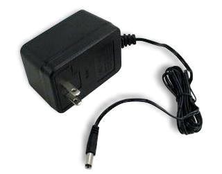
components, I think +12V/3A supply
will be enough.
Powering
Microcontroller: We need +5V supply, to power microcontroller and
surrounding circuit. I have couple of LM317 (TO-220) in inventory, so decided
to use them in my design. After all LM317 is one of the best & popular regulator.
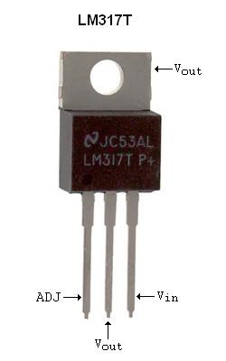
Now Power drop here is quite large i.e. 12V – 5V = 7V, but that isn’t worry cause current drawn by the MCU is small, about 100-200mA.
Thus, Power Dissipation = 7x200mA = 1.5W, attaching Heat sink to LM317 is better way to avoid heating. [Next Design, going to add LDO].
Driving Solenoids Valves:
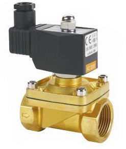
Solenoid is nothing but electromagnetic switch, available in various sizes and ratings, widely used in many industrial applications. More info.
One can use BJT or MOSFET based driver circuit. I choose BJT for easy-availability and cost of component.
We are using solenoid valves of rating +12V/5W, that is Operating current is around I = 200mA. We can drive the solenoid from MCU GPIO using driver circuit, with proper safety consideration.
I decided to go with TIP122 (NPN) Power Transistors, which is more than enough to drive the Solenoid Valves.
Calculations:
When we are driving any load using either BJT/MOSFET we are using it as a switch. So For Transistor, we need to calculate the minimum base current required to fully turn ON (“Saturate”) the transistor.
Calculating Base Current and Base Resistor:
Load Current [Solenoid Valve] = ILOAD = 200mA.
And ILOAD = IC.
From the datasheet of the Transistor we will need, β, IC, VBE (MIN).
From the Datasheet of TIP122 we have,
- β = 1000 (Typ.2500).
- IC = 5A (Max).
- VBE (MIN) = 2V to 4V.
We Have Formula for Base Current,
Putting values, Base Current = 200mA/1000 = 0.2mA
We have formula for Base Resistance,
Putting values, Base resistor = ( 4V - 0.7V) / 0.2mA = 16.5KΩ
(Standard Value = 16KΩ).
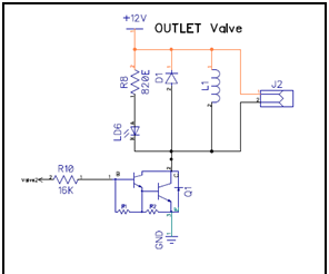
Safety: Flywheel Diode.
Generic diode 1N4007 is added, to safe guard MCU circuitry from back EMF/ Inductive kick generated by Solenoid Valve.
Indication: We have added RED LEDs (5mm), to get notified when, Valve turns ON.
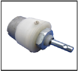
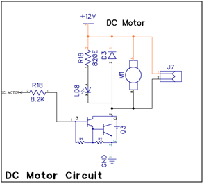
Driving DC Motors:
DC Motor which is again an Inductive load. Same principle that we used for solenoid valves applies to the DC Motor. more info.
We do not need to control the speed of a motor, simply Switch ON/OFF.
Principle behind the driving DC motor is same as for the Solenoid or Relay.
Again, we are going to use BJT based driver circuit. Same TIP122 Power transistor used here to drive DC Motor.
We are using DC Motor of rating +12V/400mA.
Calculating Base Current and Base Resistor:
Load Current [DC Motor] = ILOAD = 400mA.
And ILOAD = IC.
Using same formula as above, Calculating the base current and hence base resistance required to drive transistor.
Base Current = 400mA/1000 = 0.4mA
Base Resistor = (4V - 0.7V) / 0.4mA = 8.2KΩ
(Standard Value = 8.2KΩ).
Driving LEDs:
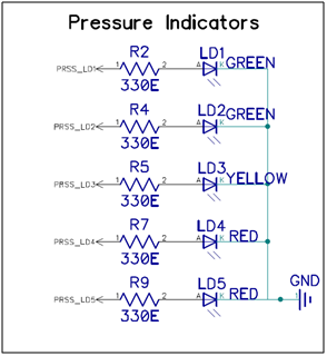
We are using 3mm LEDs (GREEN, YELLOW, RED) for indicating real-time pressure inside the filter chamber.
Driving a LED directly over MCU GPIO is simplest part. Everyone is well familiar with Hello World - Blinky program.We have,
- Supply Voltage, VCC = +5V.
- Forward Voltage, Vdiode = 2V.
- Required Idiode = 5mA-10mA
From above parameters it is easy to calculate current limiting resistor, for our circuit we are using
Rdiode = 680Ω (5mA sufficient).
Discussions
Become a Hackaday.io Member
Create an account to leave a comment. Already have an account? Log In.