Florian Cliquet
It’s now time for a v2 of the web enabled shutter, I made several years ago a first version details here. I have some feedback from the first installation and 4 years of usage.
I still control shutter with switch made for a wired group remote control, when each buses are separated you can control them individually.
The new specifications are :
- Separation of the control and the interface
- Interface
- I2C
- To put as many boards as necessary
- Compatibility
- Schneider Odace Link Plus (Ref. S520562)
- SIMU Cegeo Individuel (Ref. 2005907)
- Somfy Centralis Uno IB (Ref. 1810209)
- General button with no necessity of the control board
- I2C
- Control
- Raspberry Pi
- Remote Update of the code
- Remote Access
- Cheap
- Interface with other sensors for a more intelligent behaviour
- Raspberry Pi
- Embedded in a Din Rail enclosure
Compatibility
First, we need to understand the switch we would like to control, I have tested three brand of shutter switch linkable to a bus :
Schneider Odace Link Plus (Ref. S520562)
This is the one I really need to control, the other are optional but this could be cool to control other brand.

Schneider wall switch

Schneider switch control schema
Somfy Centralis Uno IB (Ref. 1810209)

Somfy Wall Switch

Somfy switch control schema
SIMU Cegeo Individuel (Ref. 2005907)
There is a complete teardown of this switch here

Simu Wall Switch

Simu switch control schema
Schematic

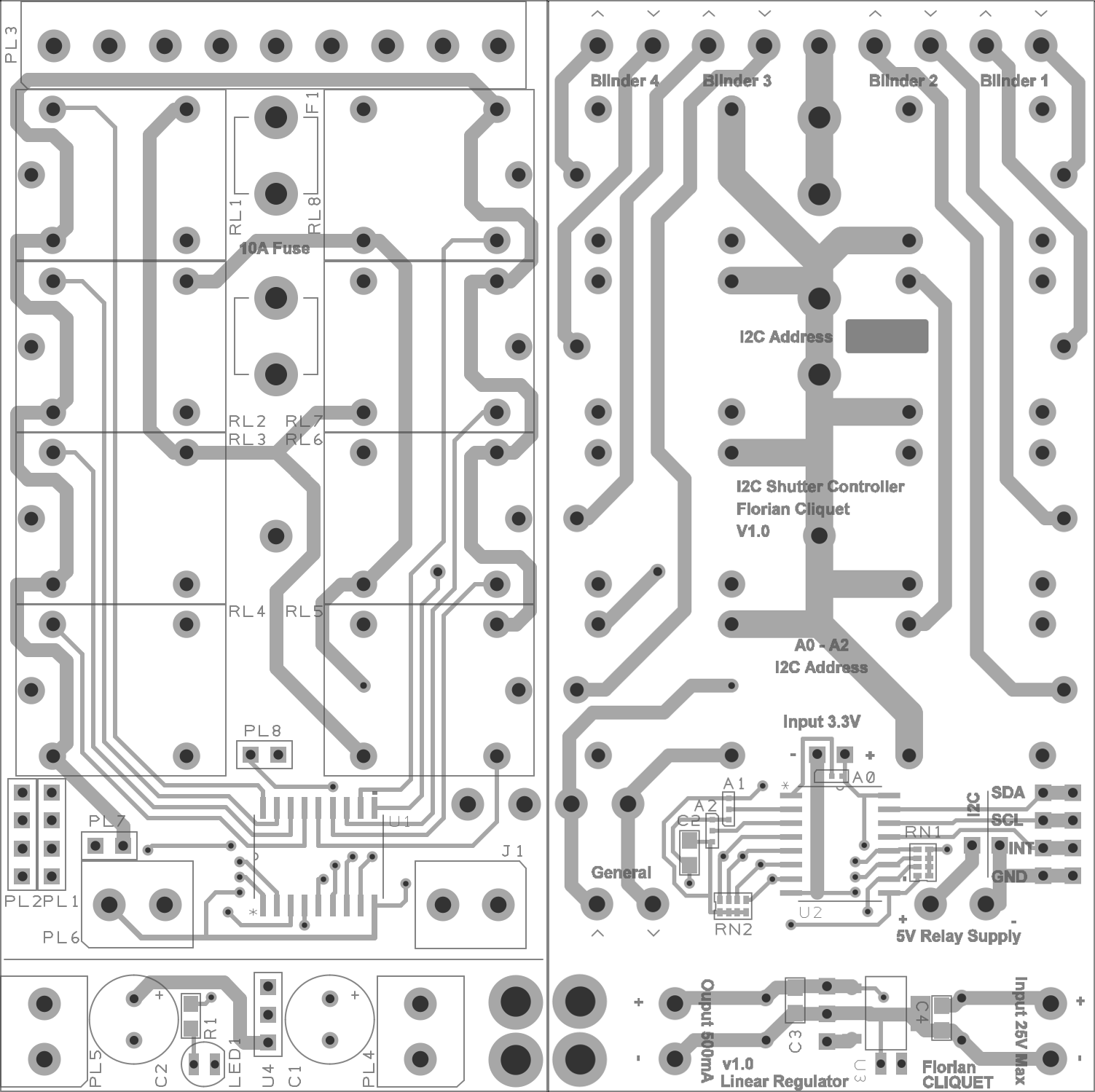
Generic control Interface with wiring configuration of each shutter switch brand
Each board was able to control 4 shutters, it needs 8 relays control by an I2C IO expander (PCA9534) with the help of 8 darlington transistors (ULN2008).

Design Spark schematics
The enclosure can receive a 86.5x156mm PCB, so I made three 86.5x50mm boards and to fill the remaining place of the 50x100mm PCB made by Seeed Studio I add a little linear voltage regulator.

Two layers PCB
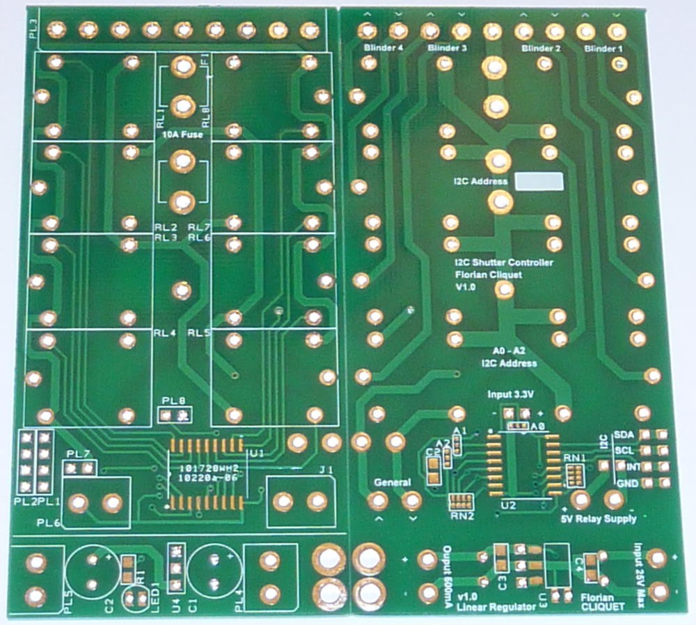
Manufactured PCB
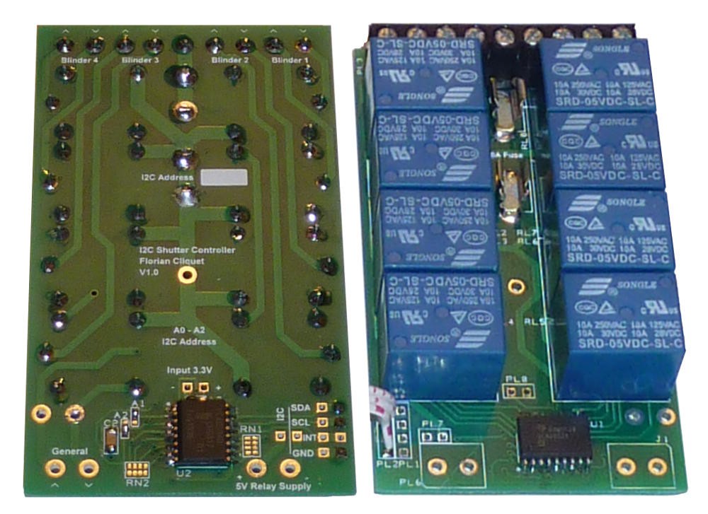
Assembled Board
Enclosure
As the different buses from each shutter switch come to the switchboard, I choose to put the 2 interface cards and the Raspberry Pi in a DIN Rail enclosure for a clean integration with the rest of the installation.

Futur place for the shutter controller

Finished controller
Control
The control is handle by a Raspberry Pi through I2C bus. This give me a lot of power for several other domotic stuff.
The intelligence is still not coded but the different input for the shutters will be :
- Windows sensors to disable automatic closure when it’s open (The v1 already closed up every one outside)
- Schedule
- Sun rise / sun set
- Alarm clock
- Alarm status
The language will be Javascript (NodeJs).
 Will Tatam
 Dan Sheadel
 Electroniclovers123